English



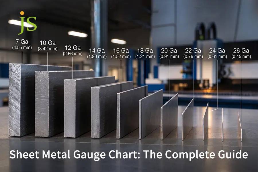

Sheet metal gauge chart is a tool that changes non-linear gauge figures into linear measurements for the thickness of carbon steel, stainless steel, aluminum, and galvanized steel sheets.
Sheet metal gauge system is inverse:
lower numbers indicate thicker material. The same gauge number does not mean the same thickness across alloys, since steel uses the Manufacturers' Standard Gauge (MSG), which is based on weight, while aluminum uses the Brown & Sharpe (B&S) geometric scale. As a result, a 16 gauge steel sheet (1.52 mm) is noticeably thicker than a 16 gauge aluminum sheet (1.29 mm).
Quality and performance for today's fabrication calls for transposing antiquated gauge numbers to decimal dimensions that meet established ASTM rolling tolerances. This critical step avoids press brake tooling damage, ensures correct bend allowances and promotes error-free assemblies. When transitioning from CAD modeling to production, verified sheet metal fabrication services translate ambiguous gauge drawings into repeatable, high-yield components.
Core Engineering Takeaways: Quick Gauge Conversion Summary
Direct Technical Conclusion: Sheet Metal Gauge is not a universally applicable unit for measuring length. A 16 gauge sheet of carbon steel (1.52 mm thick) is 17.8% thicker than a 16 gauge sheet of aluminum (1.29 mm thick). It is essential that drawings specify the thickness in exact decimals of millimeters and ASTM/ISO tolerance values.
|
Material Alloy |
Governing Standard |
16 Ga Thickness (Nominal) |
ASTM Tolerance Band |
Min Inside Bend (Rmin) |
Recommended V-Die |
|
Cold-Rolled Steel |
MSG (ASTM A1008) |
0.0598" / 1.52 mm |
±0.005" (±0.13 mm) |
1.0 x T (1.50 mm) |
6 to 8 x T |
|
Stainless Steel (304) |
USS (ASTM A240) |
0.0625" / 1.59 mm |
±0.005" (±0.13 mm) |
1.5 x T (2.50 mm) |
8 x T |
|
Aluminum (5052-H32) |
B&S (ASTM B209) |
0.0508" / 1.29 mm |
±0.003" (±0.08 mm) |
1.5 x T (2.00 mm) |
6 x T |
|
Galvanized Steel |
ASTM A653 Type B |
0.0635" / 1.61 mm |
±0.006" (±0.15 mm) |
1.0 x T (1.60 mm) |
6 to 8 x T |
Data Source: Compiled from ASTM A568, A480, A653, A240, A1008, and B209 standard specifications.
Need certified tolerance verification for your BOM? Get an Instant DFM Quote & Tolerance Audit from JS Precision within 12 hours.
Why Are Sheet Metal Gauge Numbers Backwards and Material Dependent?
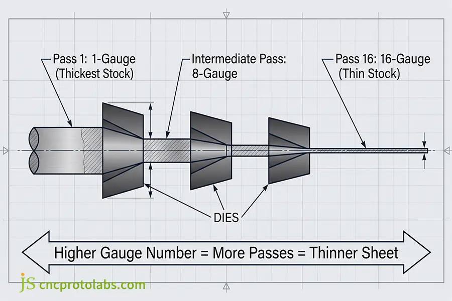
The gauge numbers are reversed because these were derived from wire drawing and rolling operations at early British iron works. The gauge number was given for the number of sequential drawing dies that the ingot was pulled through. Each stage of reduction made the sheet thinner, so the larger the gauge number the smaller the physical thickness, regardless of metallurgical standards.
The Mechanical Origin of Inverse Numbering
Knowing the history behind industrial metal fabrication helps one appreciate the reason for inverse numbering:
- First Reduction Pass: The metal billet, when passed once through the die, became 1-gauge stock.
- Subsequent Processing Passes: Further passing of this stock through another fifteen increasingly tighter dies resulted in 16-gauge stock, making for a very thin cross section.
- Work Hardening Accumulation: Every progressive drawing pass induced plastic strain, increasing the material yield strength while decreasing ductile elongation. Annealing was done to prevent brittle tensile fracture between certain processing passes.
- Modern Tooling Parallels: Modern progressive dies are equivalent to this process, where the tooling standards are those described in our specific metal stamping guide.
- Metrological Standardization: Historical records from National Institute of Standards and Technology (NIST) show that the old gauge integers were based on the number of passes made in processing, not the distance traveled, which is why today's engineers are converting them to metric units.
How Density Constants Created Separate Standards
In earlier standards, the basis was weight per square inch instead of a constant linear thickness:
- Manufacturers' Standard Gauge (MSG): Formulated to suit carbon steel taking into account wrought iron density as 480 lb/cubic ft (7,688 kg/m³) and fixing 1-inch steel at 41.82 lb/square ft. Each succeeding gauge is thus a percentage of that base weight.
- United States Standard (USS): Enacted into law by the United States Congress in 1893 for tax purposes on iron and steel plates, according to an assumed plate density of 489.6 pounds per cubic foot (7,842 kg/m³), which was somewhat different from the other standard. Stainless steel producers later embraced USS, making stainless plates somewhat thicker than carbon steel plates.
- Brown & Sharpe (B&S) Scale: This gauge is specially designed for non-ferrous metals such as aluminum, brass, and copper using a geometric progression and not the ferrous weight. The two fixed wires used to establish the scale were the 0000 gauge, which was 0.4600 inches, and the 36 gauge, which was 0.0050 inches.
- Physical Difference: Since aluminum is about one-third as dense as steel, the same areal weight equates to entirely different physical dimensions.
- Process Understanding: Mastery of these diverging metallurgical standards forms the technical foundation of what is sheet metal fabrication in custom contract manufacturing.
What Does the Standard Sheet Metal Gauge Chart Look Like with Tolerances?
A sheet metal gauge chart sets the mathematical relationship between standard gauge numbers and the measured dimension of thickness in inches and millimeters within stringent rolling tolerances. These gauge numbers are standardized according to ASTM A480 for stainless steel and ASTM A568 for cold-rolled carbon steel, and allowable sheet metal thickness tolerances usually fall between ±0.004" (±0.10 mm) for thin gauges to ±0.010" (±0.25 mm) for structural heavy plates.
When engineers consult a standard gauge to thickness conversion chart, engineers need to factor in practical tolerances in the manufacturing process rather than nominal dimensions.
Carbon Steel Sheet Thickness and Tolerance Chart (MSG Standard)
Cold-rolled carbon steel sheet follows the Manufacturers' Standard Gauge (MSG) and ASTM A568/A1008 rolling standards.
|
Gauge (Ga) |
Decimal Inches |
Metric (mm) |
ASTM A568 Range |
Primary Mechanical Use Cases |
|
7 Ga |
0.1793" |
4.55 mm |
4.32 mm to 4.78 mm |
Structural baseplates, industrial machinery frames |
|
8 Ga |
0.1644" |
4.18 mm |
3.96 mm to 4.40 mm |
Heavy machinery brackets, earthmoving cab structures |
|
10 Ga |
0.1345" |
3.42 mm |
3.22 mm to 3.62 mm |
Heavy chassis brackets, transportation mounts |
|
11 Ga |
0.1196" |
3.04 mm |
2.86 mm to 3.22 mm |
Heavy mounting plates, equipment enclosures |
|
12 Ga |
0.1046" |
2.66 mm |
2.48 mm to 2.84 mm |
Structural frames, heavy-duty shelving |
|
13 Ga |
0.0897" |
2.28 mm |
2.12 mm to 2.44 mm |
Material handling fixtures, trailer sidewalls |
|
14 Ga |
0.0747" |
1.90 mm |
1.75 mm to 2.05 mm |
Heavy electronic racks, vehicle body brackets |
|
16 Ga |
0.0598" |
1.52 mm |
1.39 mm to 1.65 mm |
Electrical enclosures, control cabinets |
|
18 Ga |
0.0478" |
1.21 mm |
1.08 mm to 1.34 mm |
Automotive interior structures, equipment covers |
|
20 Ga |
0.0359" |
0.91 mm |
0.81 mm to 1.01 mm |
Standard HVAC ductwork, light appliance housings |
|
22 Ga |
0.0299" |
0.76 mm |
0.68 mm to 0.84 mm |
Architectural flashing, lighting fixtures |
|
24 Ga |
0.0239" |
0.61 mm |
0.53 mm to 0.69 mm |
Small consumer electronics, light ducting |
|
26 Ga |
0.0179" |
0.45 mm |
0.39 mm to 0.51 mm |
Acoustic perforated liners, light acoustic baffles |
|
28 Ga |
0.0149" |
0.38 mm |
0.32 mm to 0.44 mm |
High-density heat sinks, wrapped insulation wraps |
Data Source: ASTM A568/A568M standard specifications for cold-rolled steel sheet.
Stainless Steel Sheet Thickness and Tolerance Chart (USS Standard)
Austenitic stainless steels (Grades 304 and 316) conform to the United States Standard (USS) scale under ASTM A240 and ASTM A480.
|
Gauge (Ga) |
Decimal Inches |
Metric (mm) |
ASTM A480 Range |
Primary Mechanical Use Cases |
|
8 Ga |
0.1719" |
4.37 mm |
4.14 mm to 4.60 mm |
Commercial autoclave vessels, wastewater screens |
|
10 Ga |
0.1350" |
3.43 mm |
3.23 mm to 3.63 mm |
Food processing vats, chemical pressure vessels |
|
11 Ga |
0.1200" |
3.05 mm |
2.87 mm to 3.23 mm |
Commercial dishwashers, corrosive pump shrouds |
|
12 Ga |
0.1094" |
2.78 mm |
2.60 mm to 2.96 mm |
Marine deck hardware, sanitary equipment framing |
|
13 Ga |
0.0938" |
2.38 mm |
2.22 mm to 2.54 mm |
Bottling line chutes, conveyor guide rails |
|
14 Ga |
0.0781" |
1.98 mm |
1.83 mm to 2.13 mm |
Commercial kitchen worktables, laboratory chassis |
|
16 Ga |
0.0625" |
1.59 mm |
1.46 mm to 1.72 mm |
Medical equipment enclosures, pharmaceutical casework |
|
18 Ga |
0.0500" |
1.27 mm |
1.14 mm to 1.40 mm |
Architectural cladding, food service display housings |
|
20 Ga |
0.0375" |
0.95 mm |
0.85 mm to 1.05 mm |
Cleanroom ceiling panels, interior instrument covers |
|
22 Ga |
0.0313" |
0.80 mm |
0.72 mm to 0.88 mm |
Decorative wall trim, chemical splash guards |
|
24 Ga |
0.0250" |
0.64 mm |
0.56 mm to 0.72 mm |
Precision instrument covers, exhaust cowlings |
|
26 Ga |
0.0188" |
0.48 mm |
0.42 mm to 0.54 mm |
Laboratory reagent caps, chemical sensor guards |
|
28 Ga |
0.0156" |
0.40 mm |
0.35 mm to 0.45 mm |
Heat exchanger fins, high-temperature shims |
Data Source: ASTM A480/A480M standard requirements for flat-rolled stainless steel.
Galvanized Steel Sheet Thickness and Tolerance Chart (Zinc Coated)
Galvanized steel incorporates protective zinc coatings on both sides, measuring slightly thicker than bare cold-rolled steel under ASTM A653.
|
Gauge (Ga) |
Decimal Inches |
Metric (mm) |
ASTM A653 Range |
Primary Mechanical Use Cases |
|
8 Ga |
0.1681" |
4.27 mm |
4.07 mm to 4.47 mm |
Substation ground mounts, heavy culvert plates |
|
10 Ga |
0.1382" |
3.51 mm |
3.31 mm to 3.71 mm |
Heavy utility cabinets, transformer bases |
|
11 Ga |
0.1233" |
3.13 mm |
2.95 mm to 3.31 mm |
Solar array torque tubes, outdoor equipment racks |
|
12 Ga |
0.1084" |
2.75 mm |
2.57 mm to 2.93 mm |
Heavy highway brackets, solar mounting rails |
|
13 Ga |
0.0934" |
2.37 mm |
2.21 mm to 2.53 mm |
Industrial fan housings, agricultural grain bins |
|
14 Ga |
0.0785" |
1.99 mm |
1.84 mm to 2.14 mm |
Industrial junction boxes, outdoor HVAC frames |
|
16 Ga |
0.0635" |
1.61 mm |
1.48 mm to 1.74 mm |
Telecommunications outdoor enclosures |
|
18 Ga |
0.0516" |
1.31 mm |
1.18 mm to 1.44 mm |
Commercial garage door panels, cable trays |
|
20 Ga |
0.0396" |
1.01 mm |
0.91 mm to 1.11 mm |
Spiral HVAC ducting, roofing drip edges |
|
22 Ga |
0.0336" |
0.85 mm |
0.77 mm to 0.93 mm |
Commercial metal roofing, flashing panels |
|
24 Ga |
0.0276" |
0.70 mm |
0.62 mm to 0.78 mm |
Standard commercial ductwork, light flashing |
|
26 Ga |
0.0217" |
0.55 mm |
0.49 mm to 0.61 mm |
Metal building siding, residential downspouts |
|
28 Ga |
0.0187" |
0.47 mm |
0.41 mm to 0.53 mm |
Spiral pipe fittings, lightweight chimney liners |
Costs and Workshop Measurement Standards
Raw sheet metal is procured by bulk weight, but components are fabricated by linear dimension:
- The Light-Side Mill Tendency: In steel mills, sheets are rolled to the bottom end of ASTM tolerance in order to save raw materials. Instead of rolling a sheet at 1.52 mm (16 Ga), a sheet of 1.42 mm saves production cost but lowers the mechanical loading capacity by 16.5%.
- Cold-Rolled vs. Hot-Rolled Pickled and Oiled (HRPO): Cold-rolled carbon steel coils have a uniform thickness profile over the width of the strip. Hot-rolled coil has a crown of 0. 05 mm to 0. 15 mm thicker in the center of the coil than the outer areas of the strip. Parts nested close to the coil edge will have different bend deductions than parts cut from the center of the coil.
- Cost Propagation: Quotation algorithms dynamically calculate financial exposure based on how gauge thickness errors affect part price, allowing estimators to detect material scrap prior to the cutting process.
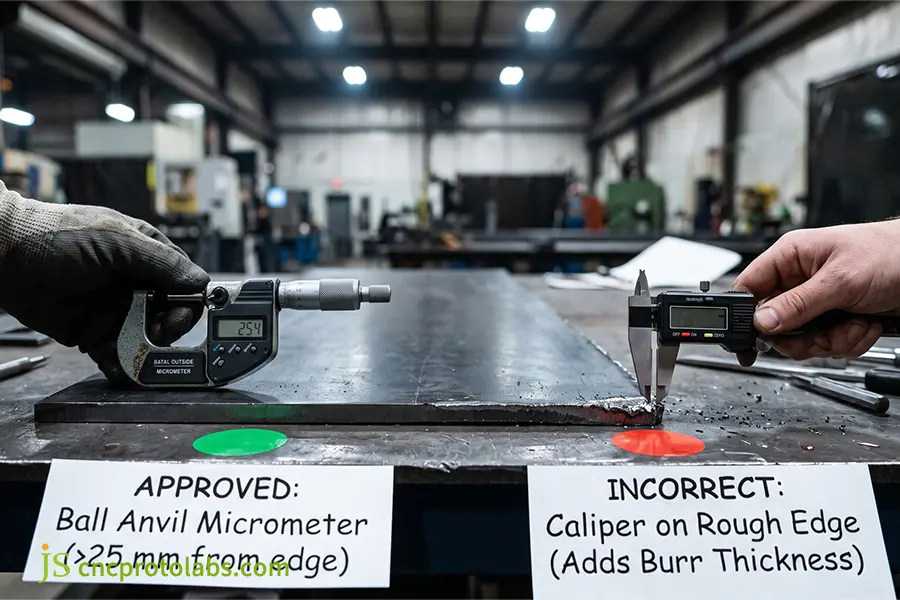
- The Caliper Trap: Measurements taken at the edges of the sheets using dial calipers provide incorrect values, as the result of shearing and laser cutting creates burrs on the edges, making the thickness appear to be increased by 0.08 mm to 0.15 mm.
- Metrology Approved: Quality managers switch the sheet metal gauge to mm and use outside ball-anvil micrometers 25 mm in from the sheared edges to measure the stock. They use an actual measurement versus a calibrated sheet metal bend radius chart to infer the press brake tool shape.
Why Does the Aluminum Sheet Gauge Chart Differ Fundamentally from Steel?
An aluminum sheet gauge chart differs from steel scales because nominal thickness definitions reflect different metallurgy standards: 16 gauge carbon steel is 0.0598" thick (1.52 mm), whereas 16 gauge aluminum is 0.0508" thick (1.29 mm). This represents a significant difference of 15%. The B&S geometric scale, as opposed to the Manufacturers' Standard Gauge of steel industry, is used for aluminum sheets.
Aluminum Sheet Thickness and Tolerance Chart (B&S / AWG Scale)
Wrought aluminum alloys (such as 5052-H32 and 6061-T6) follow the Brown & Sharpe (B&S) scale standardized under ASTM B209.
|
Gauge (Ga) |
Decimal Inches |
Metric (mm) |
ASTM B209 Range |
Primary Structural Use Cases |
|
6 Ga |
0.1620" |
4.11 mm |
3.96 mm to 4.26 mm |
Structural marine ribs, heavy rail transit brackets |
|
7 Ga |
0.1443" |
3.67 mm |
3.53 mm to 3.81 mm |
Heavy pressure vessels, commercial vehicle floors |
|
8 Ga |
0.1285" |
3.26 mm |
3.13 mm to 3.39 mm |
Heavy marine structural hulls, vehicle armor |
|
10 Ga |
0.1019" |
2.59 mm |
2.46 mm to 2.72 mm |
EV battery enclosures, structural mounting brackets |
|
11 Ga |
0.0907" |
2.31 mm |
2.21 mm to 2.41 mm |
Automotive subframe brackets, heat exchangers |
|
12 Ga |
0.0808" |
2.05 mm |
1.95 mm to 2.15 mm |
Aerospace avionics chassis, welded fuel tanks |
|
13 Ga |
0.0720" |
1.83 mm |
1.74 mm to 1.92 mm |
Electronic heat sink shrouds, medical cabinets |
|
14 Ga |
0.0641" |
1.63 mm |
1.55 mm to 1.71 mm |
Precision electronics housings, robot body panels |
|
16 Ga |
0.0508" |
1.29 mm |
1.21 mm to 1.37 mm |
Lightweight server chassis, heat shields |
|
18 Ga |
0.0403" |
1.02 mm |
0.94 mm to 1.10 mm |
Aircraft interior trim, electronic enclosures |
|
20 Ga |
0.0320" |
0.81 mm |
0.76 mm to 0.86 mm |
Lighting reflectors, thermal isolation wraps |
|
22 Ga |
0.0254" |
0.64 mm |
0.59 mm to 0.69 mm |
Acoustic shielding, lightweight decorative trim |
|
24 Ga |
0.0201" |
0.51 mm |
0.47 mm to 0.55 mm |
Nameplates, thermal isolation barriers |
|
26 Ga |
0.0159" |
0.40 mm |
0.36 mm to 0.44 mm |
High-efficiency thermal dissipators, sensor foil |
|
28 Ga |
0.0126" |
0.32 mm |
0.28 mm to 0.36 mm |
Ultra-thin electromagnetic shielding, sensor diaphragms |
Data Source: B&S conversions based on ASTM B209 specifications published by The Aluminum Association, confirming the geometric progression of non-ferrous alloys.
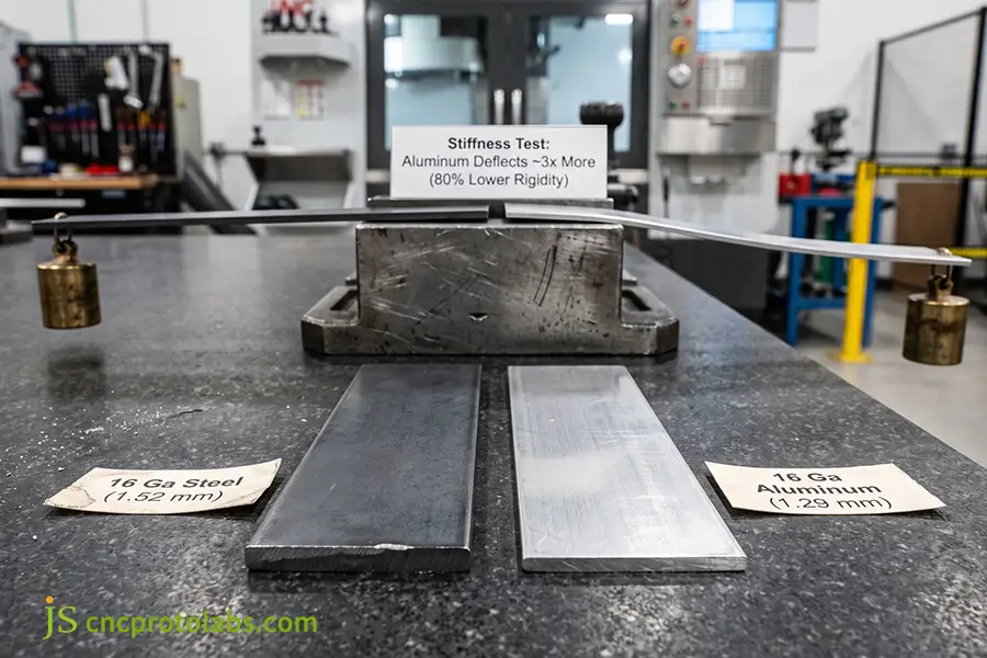
The 15% Thinner, 17.8% Thicker Gap and Stiffness of Structure
Because aluminum has an Elastic Modulus (E ≈ 70 GPa) roughly one-third that of carbon steel (E ≈ 210 GPa), together with a 15% reduction in thickness when having equal gauge values:
- The Flexural Rigidity Deficit: The Flexural rigidity of a 16-gauge 5052-H32 aluminum plate is about 80% lower compared to that of a 16-gauge carbon steel plate. The elastic displacement varies inversely proportional to the cube of the sheet thickness (1/T³).
- Design Compensation Rule: To maintain the same stiffness where steel is replaced by aluminum, designers need to increase thickness by at least 2 full gauge sizes (like 12 Ga aluminum replacing 14 Ga steel).
- Vibration and Natural Frequency: Light aluminum sheets that are sensitive to vibration have lower resonant frequency compared to the steel equivalents. The thin aluminum enclosures for chassis require stiffening features within the enclosure to avoid acoustic drumming due to fan vibration frequencies.
- Alloy Selection Parameters: Component yield strength depends on the metallurgical integrity of standard materials used in sheet metal fabrication, which balance structural rigidity against temper brittleness.
Tooling, Stamping, and Forming Considerations
There are certain adjustments that have to be done on press brake tooling and blank placement when forming aluminum:
- Grain Orientation Awareness: primary bend lines should always be positioned perpendicular (transverse) to the coil rolling grain to prevent tensile cracking along the outer radius. Bending parallel to the longitudinal coil grain will develop micro-crazing around localized areas of 6061-T6, 5052-H32 sheet stock.
- Mass Production Stamping: Long-run progressive stamping will provide adequate flow for the tool with the right stamping materials that exhibit high-strain plastic flow. Die clearances for aluminum should be 10% to 12% of material thickness per side to avoid burr pull and galling.
- Press Brake Tonnage: Aluminum needs about 40% to 50% less punch force than steel but needs larger V-die openings to avoid surface marring. Air-bend configurations are designed to correspond with the mechanical properties of the specified metal bending materials.
- Springback Differences: Aluminum of 16-gauge thickness will have 2° to 4°of springback compared to 1 for mild steel. The differences in operation of work-hardening between aluminum and steel can be found in our comparison of aluminum vs steel sheet metal bending.
Should Engineering Drawings Use Gauge or Millimeters for Dimensioning?
Engineering drawings are required to use metric millimeters (mm) or decimal inches instead of gauge designations to avoid expensive manufacturing errors. Current GD&T standards, like ASME Y14. 5 and ISO 2768-m, do not accept gauge as a valid dimensioning callout, since gauge does not have standardized unilateral tolerances. Providing the precise thickness with clear sheet metal thickness tolerance limits removes ambiguity for suppliers and supports consistent production runs.
In the dimensional tolerancing of ASME Y14.5, linear limits must define permitted boundaries of work piece dimensions and show what are acceptable work piece limits. This explains why informal limits cannot be used to certify inspection.
Engineering Drawing Callout Comparison Matrix
|
Callout Method |
Standard Compliance |
Global Supplier Usability |
Tolerance Boundary Control |
Production Risk Level |
|
Gauge Integer |
Non-Compliant |
Poor |
Uncontrolled |
Critical Risk |
|
Decimal Millimeters |
Fully Compliant |
Universal |
Absolute |
Negligible Risk |
|
Decimal Inches |
Fully Compliant |
Moderate |
High |
Low Risk |
|
Dual Metric + Ref |
Fully Compliant |
High |
High |
Low Risk |
Practical Drawing Standards for Engineering Teams
- Use Real Decimals to Model: Always use real decimal value (for instance, 1.50 mm, not a non-validated whole number) for 3D CAD sheet metal properties. The values in CAD will affect the creation of flat pattern and exporting DXF file. If non-validated solid model 2.00 mm is associated with the 14 Ga callout, a direct 0.10 mm error will occur in the flat pattern.
- Define Tolerance in Drawing Notes: Include an explicit tolerance block note:
MATERIAL: 1.50 ±0.08 mm Cold-Rolled Steel per ASTM A1008 CS Type B [16 Ga Ref]. Explicit tolerance will overwrite general loose title block tolerances. - State General Tolerances: Reference global production standards directly in the title block, such as General Tolerances: ISO 2768-m. It will ensure that the un-dimensioned laser profiles will get ±0.20 mm tolerances and formed flanges ±0.5° tolerances.
How Do Sheet Gauge and Thickness Govern Bending Tolerances and Springback?
Sheet metal gauge controls bend allowances, part tolerance for bending, and springback correction during CNC press brake processes. Even a variance of 0.1 mm in a 16-gauge sheet changes the position of the neutral axis and therefore results in changes to the K factor, causing angular differences of more than 1.5 degrees. Precision high-yield forming needs bend allowance adjustment and overbend correction according to material thickness.
Neutral Axis Physics and K-Factor Calculations
In the process of air bending, the outside bend region elongates while the inside one compresses. The neutral axis is defined as the internal layer which has no strain at all.
K-Factor Definition:
The ratio between the neutral axis depth (t) and total material thickness (T):
K = t / T
Practical K Factors:
Generally lie between 0.30 to 0.48 during air bending since the compressive yield strength is higher than the tensile plastic strength. As the inside bend radius is decreased with respect to the sheet thickness, the neutral axis moves closer to the inner surface.
The Bend Allowance (BA) Formula:

(Where θ = angle in degrees, R = inside radius, T = verified physical thickness, and K = material K-factor).
The Bend Deduction (BD) Reality:
Flat patterns are determined by subtracting the Bend Deduction from the sum of the flange lengths:
BD = 2 x (R + T) x tan(θ / 2) - BA
Any variation of 0.10 mm in raw metal thickness will influence the tangent setback and Bend Allowance values, causing a shift in the outer flanges limits.
Thickness Variance Impact:
If the drawing shows 1.52 mm (16 Ga), but the incoming sheet metal is 1.40 mm because of the negative rolling tolerance, then there will be an error of about 0.15 mm per bend in flat blank.
Engineering Tools:
Correct flat blank geometry relies on an empirically verified K-factor in sheet metal bending, which prevents dimensional drift when paired with our standardized bend allowance and K-factor guide.
Tooling Selection and Springback Compensation Guidelines
With thinning sheet metal thickness (higher gauges such as 20 Ga, 22 Ga etc.), R/T ratio increases, thereby increasing the elastic springback:
- Overbending Requirement:
In order to make a true bend of 90.0° angle in 18 ga 304 stainless steel, punch bends need to be over-bent by an angle of approximately 87.5°, compensating for the springback of 2.5°. When the material is spring hardened 301 stainless or temper aluminum, the over-bending is approximately 6.0°.
- V-Die Selection Rule:
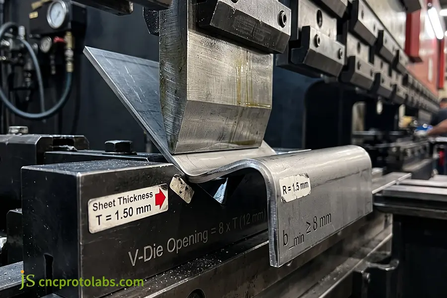
For thicknesses up to 3.0 mm (11 Ga and thinner), select a lower V-die opening width equal to 6 to 8 x T. For sheets thicker than 3.0 mm, use 8 to 10 x T. Smaller V-dies (such as 4 x T) will increase the tonnage requirement to a point where galling and punch wear will occur.
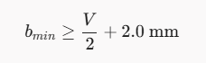
- Minimum Flange Length (bmin):
To avoid slipping of the sheet into the die pocket, bmin should satisfy:
- Tolerance Assurance: Reliable robotic cell setups require strict adherence to standard bending tolerances for formed parts. Furthermore, light-gauge chassis fabrication demands specialized methods for springback and overbending in thin sheet.
- Defect Prevention: Auditing CAD models for sheet stock tolerances resolves upstream causes of bending defects and drawing accuracy before operators load tooling.
Not sure if your CAD bend allowances are correct for mill sheet stock? Get Your Drawings Reviewed For Free by JS Precision engineers.
How to Use a Sheet Metal Thickness Chart to Compare Cutting and Forming Processes?
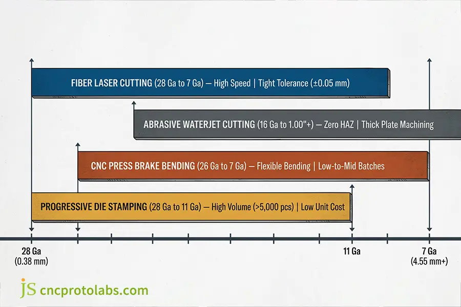
A sheet metal thickness chart enables the manufacturing engineer to determine whether laser cutting, waterjet cutting, press brake bending, or stamping dies should be used according to gauge and production volume. Thinner gauges, from 24 Ga to 16 Ga, offer maximum cutting speed and economy by using fiber laser profiling or stamping dies. However, thicker gauges, which are more than 10 Ga (3.5 mm+) and susceptible to heat distortions, can be handled efficiently using abrasive waterjet cutting.
Process Capability and Gauge Selection Matrix
|
Process |
Thickness Window |
Typical Tolerances |
Min Hole / Feature |
Economical Batch Size |
Core Technical Trade-Offs |
|
Fiber Laser |
28 Ga to 7 Ga |
±0.05 mm to ±0.12 mm |
D ≥ 1.0 x T |
1 to 5,000 units |
Minor HAZ over 10 Ga, requires N2 for clean edges |
|
Waterjet |
16 Ga to 1.00"+ |
±0.08 mm to ±0.20 mm |
D ≥ 1.5 x T |
1 to 1,000 units |
Cold process with zero HAZ, slower on thin sheets |
|
Press Brake |
26 Ga to 7 Ga |
±0.15 mm / ±0.5° |
Flange ≥ (V/2) + 2 mm |
1 to 2,500 units |
Flexible zero-tooling setup, manual cycle times |
|
Stamping |
28 Ga to 11 Ga |
±0.02 mm to ±0.08 mm |
D ≥ 1.0 x T |
5,000+ units |
High upfront die tooling, lowest per-unit cost |
Process Selection Guidelines by Thickness
- Profiling Metrology: Machinists resolving thermal taper issues balance cutting speeds against verified laser vs waterjet cutting tolerances, while high-power optical heads require specific adjustments for laser cutting thin vs thick plate. Lasers are used to cut light gauge (20 Ga to 16 Ga) at linear speeds higher than 40 meters per minute with assistance of nitrogen. For structural plates over 6.0 mm, the use of abrasive waterjet cuts through the recast layer.
- Forming Break-Even Points: Production volume drives the economic balance point between bending vs stamping, while upfront blanking costs dictate the capital split between stamping vs laser cutting. In cases where part designs have localized features such as louvers, embosses, and deep coining, combination turret punch/laser machines allow for one operation set-up.
- In-House Capabilities of JS Precision: Operating from our Dongguan facility equipped with 30 kW fiber lasers, CNC press brakes with real-time laser angle tracking, and high-speed punch presses, we maintain tolerances down to ±0.05 mm across custom sheet metal prototypes and production runs.
What Are the Real-World Cutting and Finishing Limits for Each Sheet Metal Gauge?
Fabrication for different sheet gauges means bringing the combination of laser cut parameters and post process tolerances. For example: 304 vs. 316 stainless steel or 5052 vs. 6061 aluminum sheets will cut at different focal heights and assist gas pressures to be free of burr. As well, finishes like powder coating add 0. 05 mm to 0. 12 mm each surface and must be factored into finished assembled sizes of bent gauge components.
Laser Cutting Design Rules for Precision Features
- Minimum Pierced Hole Diameter: Ensure hole diameter is either equal to or more than the material thickness (D ≥ 1.0 x T). In 3.0 mm (11 Ga) material, pierced holes 1.5 mm will create excess heat pooling resulting in blowing off the circumference of the hole and leaving behind a tapered cylindrical shape.
- Hole-to-Edge Spacing: Maintain a minimum distance of 2.0 x T for holes from sheared edges, and 3.0 x T from bend tangent lines to avoid hole elongation during bending process. Where holes have to be near the bend, cut an intermediate relief hole between the hole and bend tangent line through laser cutting.
- Corner Relief Dimensions: In 90° corners, the dimensions of the relief notches should be either equal to or larger than the thickness of the sheet metal (w ≥ T), so as to extend beyond the bend tangent line and avoid tearing of the corner.
- Micro-Tab Placement: Micro-tabs (widths of 0.40 mm to 0.60 mm) should be used for thin sheet metals that have profiles between 24 ga and 18 ga, when they are cut on flying optics laser beds.
- DFM Best Practices: Flawless pierce geometry begins with verified laser cutting design guidelines that account for thermal dissipation at sharp contour corners.
Cutting Parameters for Different Alloys
- Stainless Steel (304 vs. 316): Chemical differences cause the nitrogen assist gas to behave differently in 304 vs 316 stainless laser cutting and inhibit chromium-carbide formation on cut faces. 20 bar nitrogen at high pressure cools the liquid kerf and blows the liquid metal out of the way before it has a chance to oxidize leaving a weld-ready surface.
- Aluminum Alloys (5052 vs. 6061): To avoid greasy dross, 6061-T6 needs to be moved into the sheet core (-1/3 x T) with the optical. Check our optical configurations for 5052 vs 6061 aluminum laser cutting. 5052 aluminum is cut cleanly with high beam acceleration combined with a small nozzle diameter (1.2 mm to 1.5 mm) to increase assist gas velocity.
Surface Coating Buildup and Fitment Allowances
Neglecting the thickness of surface finishing leads to binding when assembling parts. Mechanical designers calculate dimensional buildup using physical metrics from how surface finishing works, checking pre-plating tolerances against standard definitions in what is surface finishing:
- Powder coating: Adds 0.050 mm to 0.120 mm (50 to 120 μm) per side. In a U-shaped channel bracket, powder coating increases the total thickness of the web by 0.24 mm, decreasing the sliding clearance. Internal threads (PEM nuts and tapped extrusions) have to be protected with silicone plugs prior to spraying.
- Zinc Plating: This is done through a protective film of 0.005 mm to 0.015 mm (5 to 15 μm) in thickness per side, thus maintaining the close tolerance of fasteners and pins. Chromate passivation, which is clear, yellow, or black, coats the porous zinc plating without changing any dimension.
- Anodizing (Type II and Type III): Type II sulfuric anodizing adds 0.010 mm to 0.025 mm in thickness, while Type III Hardcoat anodizing has a thickness of 0.050 mm. Pre-machining of dimensional allowance is needed when working with close tolerance hinge pins.
- Dimensional Control: Interference due to painting in bracket assemblies is prevented through 3D CAD modeling based on the finishing effect on bent part dimensions.
How Did JS Precision Solve Enclosure Jamming by Correcting Sheet Metal Gauge Charts?
JS Precision resolved a critical server rack enclosure jamming issue for a European telecommunications OEM by correcting flawed sheet metal gauge chart assumptions. The client's design used ambiguous 14-gauge callouts, which were prone to deviations due to mill-run inconsistencies of over ±0.22 mm. JS Precision used certified 2.00 mm thick cold-rolled steel with a strict tolerance of ±0.05 mm instead.
The Problem: 14.8% Assembly Scrap in 19-Inch Racks
A telecommunications equipment manufacturing company based in Europe encountered a lot of problems with assembly of their 19-inch high-density server racks:
- Symptoms: 14.8% of sliding server enclosures got jammed in the corresponding rail channels.
- Production Problem: The production lines had to be stopped for 11 weeks in order to file and grind the parts manually.
- Original 2D Drawing: The drawings used the callouts "14 GA COLD ROLLED STEEL" with ±0.5 mm overall block tolerance.
Root Cause Analysis by JS Precision
Our senior QA engineering team performed an audit of the client's design package and found the following three root causes:
- Mismatched Material Standard: The client had used nominal 2.00 mm metric sheet stock in their CAD design, but their local purchasing team had ordered 14 gauge MSG coils of nominal thickness 1.90 mm (0.0747").
- Thickness Tolerances in Mill-Run: Tolerances in the standard ASTM A568 commercial steel allowed for thickness variations of 1.75 mm and 2.05 mm across different batches.
- Tolerance Stack-Up in Press Brake Forming: There were 7 consecutive air bends with changes in neutral axis causing an accumulated variation of ±0.85 mm in channel width, which far exceeded the total rail sliding tolerance of 0.30 mm.
The JS Precision Engineering Solution
- Step 1: Consistent Metric Callout: We removed the vague "14 Gauge" specification on the drawing and called out the part as 2.00 mm (+0.00 / -0.05 mm) Cold-Rolled DC01 Steel. Precalibrated cold rolled steel sheets were used in order to ensure thickness consistency across incoming batches.
- Step 2: Experimental K-Factor Redefinition: We tested the exact yield strength of the sheet in the lab and redefined the K-factor as K = 0.42 using precise 12 mm V-dies and adjusting flat blank sizes on the CAD. Shifting the flat pattern cutouts by 0.28 mm realigned the mounting holes after plastic deformation.
- Step 3: In-process Laser Angle Correction: We moved production into CNC press brakes with laser angle detection that automatically corrects ram depth to achieve 90.0° ± 0.25° bends. This angle tracking process corrected for slight yield strength differences between sheets.
- Step 4: Powder Coating Compensation: We adjusted slide tab dimensions in flat laser blank by 0.10 mm on each side due to matte-black powder coat.

Quantified Results and Long-Term Value
- First Pass Yield (FPY): Increased from 85.2% to 99.6%, with no line stops or manual remanufacturing required.
- Thickness Consistency: Reduced from the broad spectrum of 0.30 mm to a tighter ±0.025 mm, resulting in high process capability (Cpk ≥ 1.67).
- Cost Savings: The OEM reduced assembly cycle times by 22%, saving an estimated $85,000 annually in warranty claims, scrap, and factory rework.
- Quality Certifications: All manufactured lots come with material test certificates (MTC according to EN 10204 3.1) and full CMM inspections reports created by our Zeiss lab.
(Data Source: JS Precision Internal Quality Engineering Case Report #JSP-2025-EN084, Project Telecom-Rack).
Conclusion
Using the sheet metal gauge chart guarantees accurate geometry, assembly collision avoidance, and cost-effective purchasing process. With the adoption of metric sizing in manufacturing, linking gauge sizes to millimeter thickness tolerances is a common procedure in engineering drawings. High-yield production relies on precision metal bending services to eliminate angular springback errors, while tight profiles and perforations demand calibrated laser cutting services for clean, burr-free edges.
Validate your sheet metal design and mill rolling tolerances by submitting your CAD files and 2D drawings at JS Precision. Our engineers deliver immediate DFM reviews and factory-direct pricing within 12 hours. Get an Instant Factory Quote & Tolerance Review or Talk to a Sheet Metal Specialist to ensure guaranteed fitment.

FAQs
What is 16 gauge in mm and inches for different metals?
According to standard manufacturing practices, 16 gauge is 0.0598 inches (1.52 mm) of carbon steel, 0.0625 inches (1.59 mm) of stainless steel, and 0.0508 inches (1.29 mm) of aluminum. Since the standard thickness for gauge depends on the density of the material and past rolling practices, 16 gauge will never be the same thickness among different alloys. Always consult material specific conversion tables during product design.
How can you accurately measure sheet metal gauge thickness in the shop?
Sheet metal gauge thickness can be measured using an accurate digital outside micrometer or ultrasonic thickness gauge instead of dial calipers. Always measure at least 25 mm from the edge of cut sheets of metal to avoid any erroneous readings that could arise due to shear burrs or laser dross. Ensure the surface of the metal is clean before measuring its thickness.
Is nominal gauge thickness identical to the actual delivered thickness?
No, delivered sheet metal rarely matches the nominal thickness exactly due to rolling mill allowances defined by ASTM and ISO specifications. Commercial sheets exhibit permissible positive and negative tolerances, typically spanning ±0.003 to ±0.008 inches (±0.08 to ±0.20 mm). High-precision fabrication projects requiring tight sliding tolerances must explicitly specify custom cold-rolled tolerance bands on the fabrication prints.
How does material gauge thickness affect laser cutting quality and lead times?
Material gauge plays a significant role in laser cutting speed, edge angle, and piercing time. Smaller gauges (16 to 22 Ga) can be processed fast and nitrogen assist gas can be used to achieve clean edge with no oxide formation. Larger gauges (10 Ga and smaller) should be processed slowly and with more power of the laser and with oxygen assist gas forming the oxide layer.
Why is galvanized sheet metal thicker than standard cold rolled steel of the same gauge?
Galvanized sheet metal is noticeably thicker because its nominal gauge measurement includes both the raw steel core substrate and the zinc protective coating layers on both sides. For instance, a 16 gauge galvanized sheet measures approximately 0.0635 inches (1.61 mm), whereas uncoated 16 gauge cold rolled steel measures 0.0598 inches (1.52 mm), according to ASTM A653 standards.
How should sheet thickness be designated on RFQ drawings to get the most accurate quote?
To ensure an accurate manufacturing quote, annotate part drawings with absolute metric dimensions in millimeters accompanied by ISO 2768-m tolerance limits, rather than generic gauge numbers. For example, specify "2.00 ±0.10 mm Cold Rolled Steel" instead of "14 Ga". This transparent callout eliminates supplier interpretation errors, ensures transparent raw material costing, and accelerates quotation response turnaround.
What sheet metal gauges and thicknesses can JS Precision fabricate in-house?
JS Precision fabricates custom sheet metal components ranging from ultra-thin 30 gauge (0.3 mm) foil up to heavy 3 gauge (6.0 mm) plate, alongside thick plate profiling up to 25 mm. Operating from our Dongguan facility equipped with advanced CNC punch presses, 30 kW fiber lasers, and high-precision press brakes, we maintain stringent tolerances down to ±0.05 mm for global industrial customers.
What is the typical turnaround time and quote process for custom sheet metal parts?
JS Precision delivers comprehensive DFM analysis and formal quotations within 12 to 24 hours of receiving your 3D CAD models (STEP/IGES) and 2D drawings. Rapid sheet metal prototyping prototypes typically ship in 3 to 5 business days, while low-volume production runs are completed in 2 to 3 weeks, supported by complete material certification and CMM inspection documentation.
Resource