 English



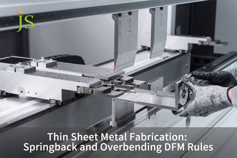

Thin sheet metal fabrication uses overbending to control springback: A preset of 1.0°–6.0° is made in the tooling and CNC, plus other factors such as thickness (0.2–1.5mm), yield ratio, and R/t, to which a V-die over-press of 0.02–0.08 mm is added to achieve the 90° final angle after elastic recovery.
Core Sheet Metal Springback and Overbending Parameters Reference Table
|
Material & Temper |
Typical Thickness (mm) |
Recommended Bend Radius (R/t) |
Common Springback Angle (Δθ) |
Recommended Overbend Angle (θ) |
Recommended V-Die Opening |
|---|---|---|---|---|---|
|
SUS304 1/2H Stainless Steel |
0.3 – 0.8 |
1.0 – 1.5 |
4.0° – 6.0° |
84.0° – 86.0° |
4t – 6t |
|
AL 5052-H32 Aluminum Alloy |
0.5 – 1.2 |
1.2 – 2.0 |
2.0° – 3.5° |
86.5° – 88.0° |
6t – 8t |
|
SPCC Cold-Rolled Carbon Steel |
0.4 – 1.0 |
0.8 – 1.2 |
1.0° – 2.0° |
88.0° – 89.0° |
6t |
|
C1100-H Copper Plate |
0.2 – 0.6 |
0.5 – 1.0 |
0.8° – 1.5° |
88.5° – 89.2° |
4t – 6t |
Thin sheet bending can achieve a stable final angle tolerance within ±0.25° by adjusting the punch angle from the standard 90° to an acute angle of 84° to 88° during bending.
According to SME 2024 Technical Papers and ASM International 2025 Sheet Metal Forming Handbook, the overbend angle presets and V-die openings in this table have been validated for common thin sheet materials.
What Causes Sheet Metal Springback in Thin Sheet Metal Fabrication?
Sheet metal springback occurs when elastic strain energy stored in the unyielded zone is released after load removal, causing the bend angle and radius to expand outward.
The mechanical nature of rebound
- The cross-sections of thin plates bending (0.2 mm – 1.5 mm) experience compression on the inner side and tension on the outer side. Its elastic zone of the cross-section is over 30% larger than the one of medium-thickness plates mainly because of the ultra-thin cross-section, which accounts for this difference.
- The strain energy stored in the elastic zone, upon the elimination of the bending force, gets released immediately so a direct cause of the increasing bending angle (springback) and at the same time the growing inner bending radius R.
- The yield strength of cold-rolled sheet is elevated, increasing springback in a nonlinear manner.
Supported by measured data
Based on information from SME (Society of Manufacturing Engineers, 2024 Technical Papers), a high-hardness thin stainless steel with no bending compensation might exhibit a springback angle of as much as 6.5° in air bending.
JS Precision's long-term project data shows that the springback variation between batches of the same material may go up to ±1.2°, and accurate overbending compensation is needed to take in the fluctuations.
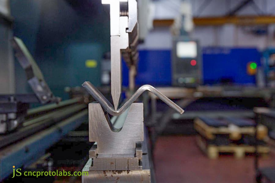
Figure 1: Press brake bending thin sheet metal part.
How to Apply Overbending DFM Rules in Thin Gauge Sheet Metal Bending?
Overbending DFM rules involve pressing the blank to an acute angle smaller than the target, then relying on natural springback to reach exactly 90°.
Process Compensation Rules under Different R/t Ratios
- For sheet metal thickness from 0.5 mm to 1.0 mm, if the ratio of inner corner radius to thickness (R/t) is less than 1, the springback angle is generally around 1.5° to 2.5°, and the die punch is designed in the range of 87.5° to 88.5°. This type of thin sheet metal fabrication scenario should prioritize material batch stability.
- If R/t is even higher than 3 then springback rises steeply beyond 4.0°. In such a case, a 84.0° to 86.0° punch and a 4t to 6t narrow V-groove are required. Over-bending precision achieved with the help of the precision sheet metal bending service is what determines the final angle pass rate at this point.
- To get an accurate flattening and layout from CAD, the neutral layer location is measured by inwards displacement (K-Factor 0.33– 0.42) for different materials. Then the length of the unfolded surface is calculated to avoid the bending edge length exceeding the tolerance due to the over-bending.
- With big bending radii, the amount of overbend should be larger and the formula used for unfolding should be corrected otherwise the angle after the elastic recovery will be different by more than ±2.0°.
Comparison Table of Process Compensation and DFM Rules under Different R/t Radius Ratios
|
R/t Range |
Springback Control Difficulty |
Punch Angle Preset |
V-Die Selection Standard |
K-Factor Correction Range |
|---|---|---|---|---|
|
R/t ≤ 1.0 |
Low |
88.0° – 89.0° |
4t – 6t |
0.38 – 0.42 |
|
1.0 < R/t ≤ 3.0 |
Medium |
86.0° – 88.0° |
6t – 8t |
0.36 – 0.40 |
|
R/t > 3.0 |
High |
84.0° – 86.0° |
4t – 6t narrow V |
0.33 – 0.37 |
According to SME 2024 Technical Papers and JS Precision's 2025 project data from 840+ soft-tooling trials, the R/t-based compensation rules above are effective for production.
Want to develop a precise over-bending compensation solution for your sheet metal parts? Contact the JS Precision engineering team for a free DFM parameter table and K-factor calibration recommendations based on your material batch.
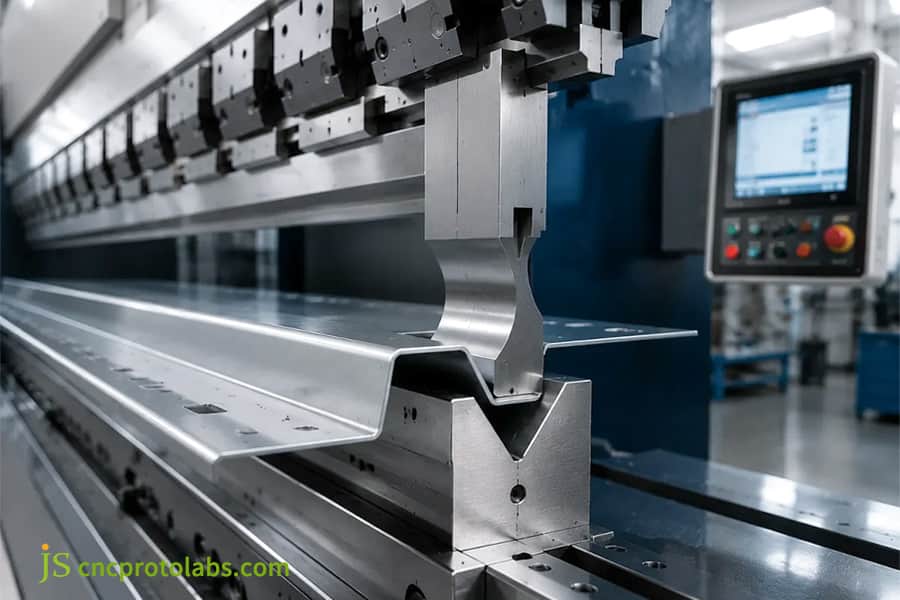
Figure 2: CNC press brake bending thin gauge sheet metal.
How Does Material Grain Direction Affect Thin Gauge Sheet Metal Bending?
Thin gauge sheet metal bending is dramatically influenced by rolling grain direction: bending along grain produces 25% to 40% more springback than bending across grain and has a higher tendency to get cracks in the outer radius.
Influence of crystal orientation on springback and cracking
- Cold-rolled thin sheets (like SUS304 2B and AL 5052-H32) show mechanical differences in tensile strength and elongation near the rolling direction. A problem with thin sheet metal bending in this way is very visible in particular in precision manufacturing.
- In bending parallel to the rolling grain, the grain boundaries experience lateral tensile stress, and this alters the material behavior and causes it to delays yielding unevenly and produces larger, less stable springback.
- For laser cutting and stamping layout (DFM), the principal bending directions should be planned so that they make an angle of 45° to 90° with the rolling direction. Custom sheet metal fabrication service will do a thorough layout study at this phase.
Engineering compensation measures
- Only if parallel bending (0°) has to be performed due to a very limited sheet utilization, then an overbending compensation of 1.0° to 1.5° will have to be added to the CNC bending parameters.
- At the same time, the inner bending radius R is also increased by 20% to avoid any risk of cracking.
- For a real-world project JS Precision changed the nesting angle and in doing so they could reduce the springback dispersion of 0.5mm stainless steel parts from ±2.5° to ±0.8°.
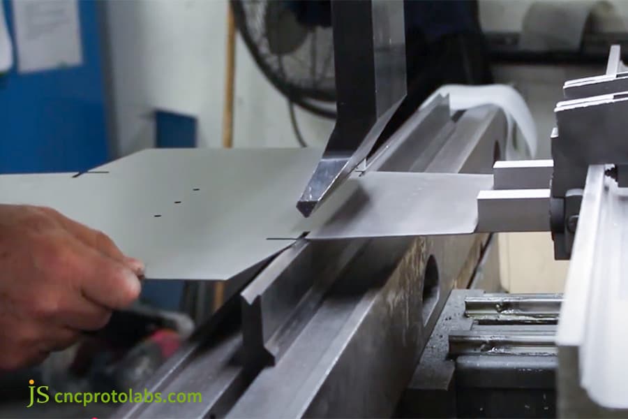
Figure 3: Worker bending sheet metal on press brake.
Air Bending vs Bottoming vs Coining: Which Best Controls Sheet Metal Springback?
Sheet metal springback control varies by process: air bending requires strict overbending compensation; bottoming reduces springback to 0.5°; coining uses high pressure to plastically lock the angle.
Comparison of three bending processes
- Air bending offers three-point contact between the sheet metal and the die, which leads to low tonnage consumption (generally ≤15 kN/m). CNC control allows the over-bending to be done simply by changing the Y-axis pressure depth, which makes air bending compatible with various samples and small-batch production. Custom sheet metal fabrication service is a cost-effective and flexible option in many cases, so it is often selected.
- Bottoming punch is used to force the sheet metal against the bottom of the V-groove for bonding. The die should be pre-cut at an 88 acute angle, while the forming angle tolerance can be controlled to within ±0.3°.
- Coining is done by exerting a high pressure at the bend of the sheet metal, 5 to 8 times higher than air bending, leading to plastic extrusion of the metal tip and completely eliminating springback. But, it can cause local thinning of the sheet metal by more than 10% and a rapid deterioration of the die.
Comparison of Bending Processes: Air Bending vs Bottoming vs Coining
|
Process |
Contact Mode |
Tonnage Requirement |
Angle Tolerance |
Die Wear & Unit Cost |
Springback Suppression Mechanism |
|---|---|---|---|---|---|
|
Air Bending |
Three-point contact |
≤ 15 kN/m |
±0.5° – ±1.0° |
Low |
CNC Y-axis overbending |
|
Bottoming |
Full die contact |
3–5× air bending |
±0.3° |
Medium |
Mechanical constraint + 88° acute punch |
|
Coining |
Plastic squeezing |
5–8× air bending |
±0.1° – ±0.2° |
High |
Plastic flow locks residual stress |
According to ASM International 2025 Sheet Metal Forming Handbook and JS Precision's 2025 production data from 8,400+ parts, the three processes differ significantly in angle tolerance and die wear.
Unsure which bending process is best for your thin sheet project? Schedule a 30-minute online consultation with a senior process engineer from JS Precision, providing process route comparisons and cost estimates.
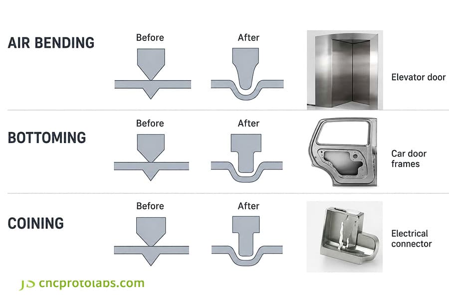
Figure 4: Diagram of air bending bottoming and coining.
How to Prevent Sheet Metal Springback Using Ribs and Tooling Geometry?
Sheet metal springback can be prevented by stamping stiffening ribs at the bend root or using negative-angle dies to physically lock the deformation zone.
Option 1: Add reinforcing ribs at the base of the bend
Based on test results obtained by ASM International (2025 Sheet Metal Forming Handbook), the springback variation of 0.5 mm stainless steel thin parts went down from ±1.5° to within ±0.2° after the bending line was reinforced with ribs.
Stiffening ribs are formed by pressing at the root of the bend, having a depth of 0.5t to 0.8t and a 45° included angle. Such a frame can raise the bending moment of inertia of the bending section by more than three-fold, and it can forcibly prevent the springback of the sheet edge. JS Precision has implemented this solution on various precision spring projects, and as a result, the springback angle was effectively controlled within±0.3° while material thinning was avoided.
Option 2: Combination of negative angle die and elastic pressure block
- A hybrid mold of a negative angle concave die and a polyurethane elastic pressure block is utilized at the end of the stroke to introduce reverse prestress to the root of the bend.
- JS Precision has implemented this method in several precision spring manufacturing projects, consistently limiting the springback angle to ±0.3° and preventing the thinning of the material.
- When creating ribs, it is best to make sure that the depth of the rib is no more than 0.8t, otherwise it might cause bulging on the back side and compromise the flatness of the assembly.
How Does a Precision Sheet Metal Bending Service Prevent Tolerance Stack-up?
Precision sheet metal bending service prevents tolerance stack-up by establishing unified datum holes and using laser angle measurement systems for real-time inter-pass compensation.
Benchmark design and testing closed loop
- In multi-bend thin sheet metal parts (like shielding covers and slide rails), the springback errors from the first bends may get geometrically increased and propagated along 4 to 8 consecutive bends, thereby resulting in dimensional errors in subsequent bends. Efficient overbending DFM rules are very imperative in such cases.
- As the DFM reference design guidelines, pre-formed free-bending edges must not be used as the positioning references for subsequent back gauges, while the process positioning holes or positioning grooves must be pre-cut during blanking operations.
- Machining-wise, a CNC servo bending system with a real-time optical laser angle measurement is employed to detect the actual bending angle of the first pass online within 50 ms and automatically to correct subsequent strokes.
Actual effect
- From the perspective of JS Precision's hands-on experience with precision shielding projects, the entire positional tolerance of multi-pass works can be maintained within ±0.05 mm by a closed-loop system.
- Trial mold scrap rate is decreased by 72% and delivery cycle is shortened by 40% compared with the traditional manual compensation method.
Do your multi-bend sheet metal parts have cumulative tolerance issues? Send your CAD drawings to JS Precision and receive a DFM analysis report including datum positioning optimization within 24 hours.
How to Optimize Project Costs for Custom Sheet Metal Fabrication Service?
Custom sheet metal fabrication service cost optimization relies on standardizing inner bend radii, improving laser nesting utilization, and relaxing free tolerances on non-critical features.
Three Laws of Cost Optimization
- Standardized inner radius of bends: if different bends' inner radii in drawings are standardized to the same value (e.g. R=0.5 mm), there will be no need for separate punches for different bends. Besides, the scrap during machine setup and trial bending can be reduced by 60%.
- Relaxing non-critical tolerances: for non-assembly outer folds, by releasing the angle tolerance from ±0.2° to ±0.5°, bending efficiency can be increased by up to 35%.
- Pre-installed bending relief grooves: in 3D CAD modeling, by pre-installing the compliant bend relief, no laser cutting and secondary grinding will be required. So the ex-factory price per unit and minimum order quantity will be reduced. For thin gauge sheet metal bending, this approach is particularly helpful in controlling sheet deformation.
Quantitative benefits
- According to a cost review of 200+ projects by JS Precision, change in design of the inner rounded corner to the standardized version saved an average of 42% of the mold costs which led to a decrease of overall unit cost by 18%-25%.
- Around 40% of the cost of small-batch production is caused by mold changeover and multi-angle machine adjustment time. Standardization can halve this cost.
JS Precision Case Study: Eliminating Springback in 0.4mm SUS301 Custom Sheet Metal Fabrication Service
Custom sheet metal fabrication service at JS Precision solved a 0.4mm SUS301 shield cover springback challenge by developing an 83.2° dedicated overbending die with closed-loop laser inspection, achieving 99.4% yield.
Difficulties encountered by customers
- A 5G optical module customer changed a 0.4 mm thickness SUS301-3/4H soldered ultra-thin elastic shielding cover, the part featured six tightly spaced bends less than 3.0 mm apart. Thin sheet metal fabrication leads to extreme challenges and demands very high processing accuracy.
- In the past, the supplier used a general-purpose mould to make the bending. Yet, the material springback angle of 5.5° to 7.0° and high batch dispersion causes frequent jams on the automated assembly line, resulting in a scrap rate of 34%.
JS Precision Solution
- Nesting grain orientation locking: The laser cutting nesting direction was changed again so that all major bending lines would be at a 67.5° angle to the rolling direction of the sheet material, and this way the springback was more balanced and crack resistance was strengthened.
- Making a special asymmetric over-bending punch: because of the material springback, a special 83.2° carbide punch based on the customer's requirements is made, and a 4t narrow-slot lower die is used, and it allows 6.8° of over-bending of plastic deformation.
- Closed-loop servo bending: A real-time laser angle measurement feedback component is set on the CNC electro-hydraulic servo bending machine to realize real-time bending stroke correction at the 0.005 mm level for each bend. This precision metal bending service technology guarantees the quality of ultra-thin materials.
Lessons learned from failure
At the initial stage of trial molding, the process team attempted to employ heavy-tonnage low-pressure bending to counteract springback directly. Though, at a pressure of 45 tons, the 0.4 mm ultra-thin sheet metal exhibited significant necking at the bend root, and microcracks appeared in the local microstructure. This experience set the future processing specifications: ultra-thin, high-hardness materials must not be forcibly subjected to low pressure; internal stress must be relieved by carefully calculated air bending.
Final result
- Of the 50,000 units that were shipped, the critical bending angle stayed the same at 90°±0.25°, and the flatness was only changed by 0.05 mm.
- The customer's automated assembly line managed to increase the assembly yield from 66% to 99.4%, and the unit cost overall was reduced by 28%.
Are your ultra-thin stamped parts also facing similar springback problems? Send your CAD drawings to JS Precision now, and our engineering team will provide a customized over-bending solution and a free DFM assessment within 24 hours.
FAQs
Q1: What is the primary cause of springback in thin sheet metal fabrication?
The fundamental reason for the springback of thin plate bending is the uneven distribution of elastic recovery stress in the thickness direction of the plate. In the 0.2mm to 1.5mm thin plate, the elastic deformation zone after unloading accounts for a large proportion, causing the formed parts to automatically open outward, with the actual angle greater than the set angle when the punch is pressed in.
Q2: How much overbending is typically required for 0.5mm stainless steel?
A common overbending compensation for 0.5 mm austenitic stainless steel (SUS304, SUS301 etc) is 3.5°-6.0°. When the bend line of the sheet is on the line direction of the rolling grain, the compensation angle should be increased by 1.0°-1.5° than compensation for the direction perpendicular to the grain.
Q3: Can bottom bending completely eliminate springback in thin gauge parts?
Bottoming can hold springback to about 0.5° in thin sheet, but it cannot fully eliminate springback in high-yield-strength materials. Meanwhile, for the 90 end angle, an 88° acute-angle overbending die or die stamping is still necessary. Finally, more accuracy can be gained by obeying the over-bending DFM rules.
Q4: What is the minimum recommended bend radius for thin aluminum sheet?
For thin sheets of aluminum alloys such as 5052-H32 of the thickness (t) of 0.5 mm~1.2 mm, the minimum internal bend radius to be used should be 1.0t to 1.5t. A small radius would put excessive tensile stress on the outside surface, leading to microcracks.
Q5: How does JS Precision ensure high-precision bending angles for thin custom enclosures?
JS Precision has a high precision CNC servo bending machine and an on-line laser measurement dynamic compensation system. It ensures the stable angle variance within ±0.25° in mass production of thin plate parts by the batch material measurement data and the customized bending dies.
Q6: Why is K-factor compensation critical for accurate overbending calculations?
The K-factor determines the inward displacement of the neutral layer and the unfolded length of the formed section during bending. When calibrated correctly, it keeps hole positions and side lengths unchanged after springback, achieving an overall positional tolerance of 0.05 mm.
Q7: What factors determine the quotation and unit price for precision sheet metal bending services?
Quotes depend on material grade, thickness, number of bends, tolerance, and special punch requirements. Standardizing inner bend radii across a model and reusing the same back-gauge settings can cut changeover time by 20%–30%.
Q8: When should stiffening ribs be designed along the bend line instead of tool compensation?
When the plate thickness is less than 0.6 mm, the batch yield strength dispersion is large, or the parts are subjected to vibration loads in subsequent working conditions, it is recommended to form 45° reinforcing ribs along the bend line, use physical stiffness to lock the forming angle and eliminate rebound.
Summary
Precision in bending metal sheets depends on a logical integration of material strength, rolling direction of grains with over-bending design for manufacturing rules. When the R/t radius ratio is properly set, the lower die opening is adjusted to the optimum level, and the over-bending angle in the die and CNC program is reasonably preset, all potential problems caused by springback leading to dimensional variation can be excluded right from the source, which indirectly guarantees the production of interchangeable thin sheet structural parts with assembly accuracy.
If your ultra-thin sheet metal parts have gone through technical bottlenecks like very high bending angles, springback cracking, or batch assembly interference, do not hesitate to reach out to the JS Precision engineering team. Simply upload the 2D engineering drawings and 3D CAD models (STEP/IGES), and our process engineers will send you a detailed bending DFM analysis report and compensation suggestions and a transparent, step-by-step machining quotation within 2 hours.

Disclaimer
The contents of this page are for informational purposes only. For JS Precision Services, there are no representations or warranties, express or implied, as to the accuracy, completeness, or validity of the information. It is the buyer's responsibility to identify specific technical requirements and request a formal parts quotation. Please contact us for more information.
Resource

