 English




Sheet metal bends fail drawing specs primarily due to uncompensated springback (1°–3°), inaccurate K-factor calculations, omitted bend reliefs, raw material thickness variations (±0.05 mm), and improper V-die selection. Calibrating tooling to actual material thickness and grain direction restores bend tolerances within ±0.05 mm. Bending deviations often bring engineers to a standstill and cause the whole production line shutdown. Classical machining practices rely on standard CAD coefficients without accounting for thickness or texture, thereby leaving springback tolerances unregulated.
This paper outlines five main causes of springback defects which if corrected will bring the defect rate down to 2.1% with a two-hour DFM review done with JS Precision. If variables can be controlled, rework won't be necessary anymore.
5 Major Bending Failure Defect Comparison Matrix
The table below compares the manifestations, root causes, and control standards of five types of core defects.
|
Core Failure Cause (Failure Cause) |
Physical Cause and Mechanism |
Drawing Drift |
JS Precision Prevention and Control Parameters |
|---|---|---|---|
|
Reason 1: Uncompensated springback of bending angle |
Residual elastic strain release after metal forming unloading |
90° bend angle springs back to 87°–88°, angle out of tolerance |
Preset 1°–3° overbend compensation angle, bottoming correction to release residual stress |
|
Reason 2: K-factor / flat pattern calculation error |
Applying theoretical K-factor instead of measured elongation |
Total unfolded length exceeds ±0.25 mm, cumulative edge distance exceeds standard |
Correct K-factor from 0.44 to 0.38, strictly control unfolded length per DIN 6935 |
|
Reason 3: Missing or undersized process relief groove |
Bend line close to part contour without notch |
Adjacent flange edge distorted by tension, micro-cracks at corners |
Add 2.5 mm deep rectangular relief groove (depth ≥ thickness + 0.5 mm) |
|
Reason 4: Raw material batch thickness tolerance fluctuation |
Batch sheet thickness fluctuates between 1.95 mm–2.05 mm |
Under same machine stroke, angle dispersion of same batch parts exceeds ±1.5° |
Optical dynamic thickness measurement compensation, fine-tune back gauge and stroke for each batch of raw material |
|
Reason 5: Wrong lower die V-groove opening selection |
Undersized V-groove causes excessive local concentrated stress |
Inner radius inaccurate, deep scratches or micro-cracks on surface |
Strictly enforce 8x material thickness (8V) opening ratio to match standard punch radius |
Reference: ISO 2768-m:1989 – General tolerances for linear and angular dimensions without individual tolerance indications, specifying ±0.5° for medium precision class.
Through engineering adjustments, batch tolerances can be reduced from ±0.25 mm to ±0.05 mm.
Key Takeaways (Core Business & Technical Points)
- Springback Pre-compensation: set aside 1° to 3° degrees for bending compensation to get rid of springback problems.
- Flat Pattern Correction: instead of the pre-default 0.44, input the measured K-factor of 0.38 to keep the deviations caused by successive processes under check.
- Relief Groove Standard: Insert ≥2.5 mm breaking channels or slots along corners as relief grooves to hinder cracking or splitting of corners.
- DFM Acceleration: provide a DFM response within 2 hours that speeds up the delivery of samples to a client by 40%.
Why Does Uncompensated Springback Distort Flange Angles?
Why uncompensated springback distorts flange angles stems from elastic recovery after pressure release. Effective sheet metal springback compensation requires overbending or coining, as bend angles drift 1° to 3° from specs without it.
Why do sheet metal bends not match technical drawing angles
When metal fibers recover under an elastic way, that is what is called springback. If bend angles are not controlled correctly, it will result in a small deviation of 1° to 3° of the final angle, which is a common cause of assembly problems.
Sheet metal springback compensation
JS Precision follows a compensation process that consists of a 1° to 3° overbending angle plus a pressure correction, and that is based in DIN 6935. The overbending is determined by referring to material's yield strength of 2°, for example SPCC, and a stress releasing period of 1.0s pressure is prolonged.
Sheet metal bending defects
Defects such as dents, cracks, and variation in length are some common problems. Small cracks can be prevented by using an 8V opening ratio of the die, together with ≥2.5 mm tear grooves. These kinds of controls are already integrated in precision sheet metal fabrication services provided by us.
Upload Your Drawing now for a free 2-hour DFM feasibility evaluation and eliminate bending defects before mass production!
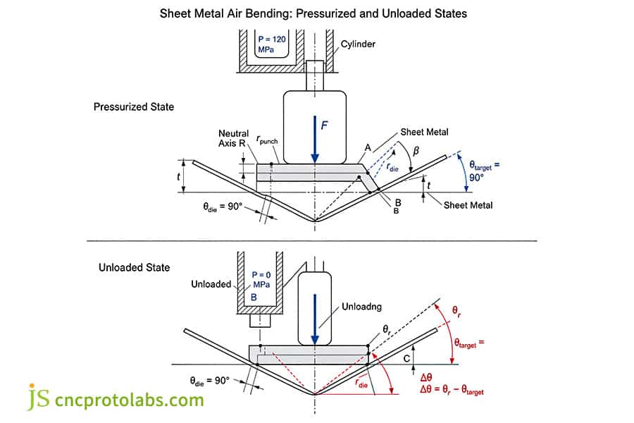
Figure 1: Air bending diagram showing pressurized and unloaded states with springback.
How Does Incorrect K-Factor Skew Flat Pattern Calculations?
K-factor in sheet metal is critical because an incorrect value misjudges neutral axis position. Default CAD K-factor 0.44 causes ±0.35 mm drift, while true accuracy requires calibrating to 0.38 for cold-rolled alloys.
Factor K in sheet metal
Factor K varies with the materials, thickness, and bending method. JS Precision measures the real K-factor through test piece bending, which then becomes a reference for the correction of the sheet metal springback.
Bender allowance tolerance
We physically bends the test pieces to lock the tolerances within ±0.05 mm: cutting test pieces, making a 90° bend, measuring the outside leg length, and computing the factor K.
Sheet metal bending accuracy
The cumulative error was brought down from ±0.35 mm to within ±0.05 mm after calibration of factor K to 0.38, securing the pass of the first piece test.
Reference: DIN 6935: 2011 – Cold bending of sheet metal; calculations of bend allowances and springback angles for cold-rolled alloys.
When Does Omitted Flange Relief Cause Corner Tearing?
Omitted flange relief causes corner tearing when bend lines lack clearance, a common issue among sheet metal bending defects. Metal folding compresses internal material, tearing adjacent surfaces.
Sheet metal bending defects
Getting corner tears is very expensive. If you do not make relief cuts, then the stress concentration when the material flows will result in fracture. The sheet metal fabrication engineering guide states that the tear depth must be more than the amount of thickness plus the inner radius combined.
Bend deduction tolerance
Tear groove size has an impact on accuracy: Relief Width ≥ T; Relief Depth ≥ R + T + 0.5 mm, which allows for free material flow.
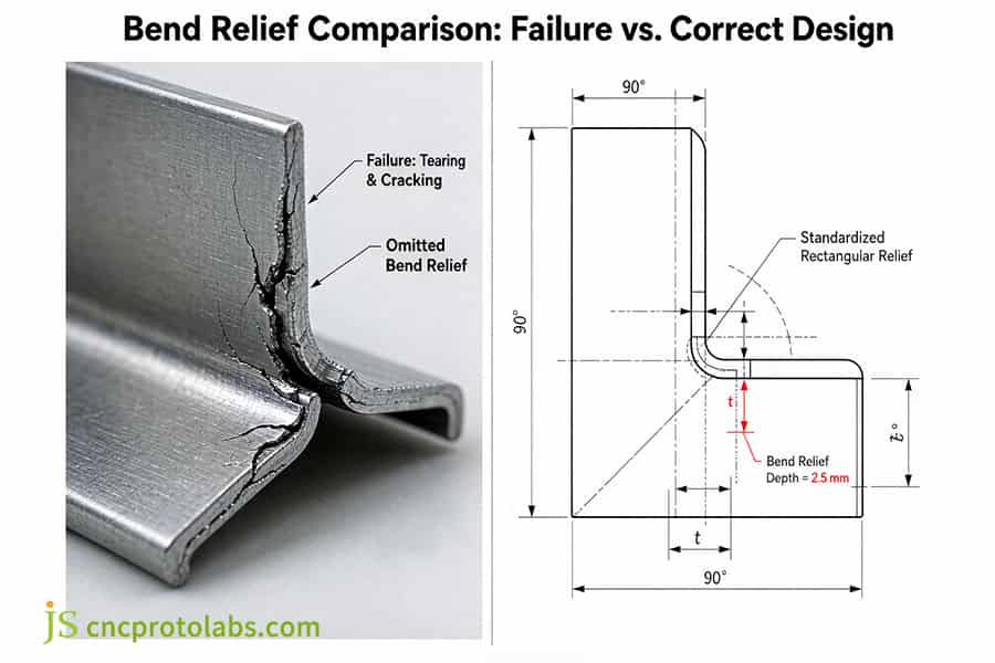
Figure 2: Bend relief comparison showing failure tearing vs correct design in sheet metal.
Why Do Raw Sheet Thickness Variations Ruin Bend Accuracy?
Thickness variations directly undermine sheet metal bending accuracy because air bending relies on punch penetration depth. Fluctuation between 1.95–2.05 mm shifts tonnage, causing angular deviations beyond ±1.5°.
Sheet metal bending accuracy
JS Precision's optical thickness compensation system automatically adapts to cancel out the ±1.5° drift that is caused by ±0.05 mm fluctuations, making the parts from the same batch look as if they have been produced by the same machine see metal bending tolerances guide.
Bend deduction tolerance
Thickness variation causes bend deduction; 0.05 mm change in neutral axis offset is 0.003 mm. We measures and recalculates compensation per batch. Uncompensated thickness variations lead to sheet metal bending defects such as irregular angles, waviness, and wear.
Reference: ASTM A480/A480M: 2022 – Standard specification for general requirements for flat-rolled stainless and heat-resisting steel plate, sheet, and strip, covering thickness tolerances of ±0.05 mm.
How Do Wrong V-Die Openings Distort Inside Bend Radii?
Wrong V-die openings are a subset of press brake tooling errors that distort radii when width fails to match 8x thickness ratio. Undersized V-die concentrates stress, gouges surfaces. Correct die selection stabilizes radii.
Press brake tooling errors
Common errors include punches getting worn and V-die width inaccurate. An overly narrow V-die causes reduction of inside radius which results in stress concentration.
Air bending vs bottoming tolerances
|
Parameter |
Air Bending (Wrong 6V Die) |
Air Bending (Correct 8V Die) |
Bottoming (8V Die) |
|---|---|---|---|
|
Inside Radius Accuracy |
±0.3 mm |
±0.15 mm |
±0.05 mm |
|
Surface Condition |
Visible die marks |
Clean |
Mirror-finish possible |
|
Angle Consistency |
±2.0° |
±0.5° |
±0.2° |
Data Source: ISO 10791-1: 2015 – Test conditions for machining centres, Part 1: Geometric tests for press brake and forming equipment accuracy verification.
Why Does Sheet Metal Grain Direction Cause Flange Cracks?
Sheet metal grain direction causes cracks when bend lines parallel rolling orientation. Elongated grains reduce ductility. Bending perpendicular or 45° across grain eliminates tearing.
Sheet metal grain direction
Grain direction is a very important issue - bending cold rolled sheets in the parallel direction often means the material becoming brittle. The custom sheet metal design for manufacturing guide says that the bending line should cross the grain at a 45° or 90° angle.
Bend deduction tolerance
Grain orientation also changes the bend deduction requirement; crossing the grain calls for a higher K-factor (0.02–0.03). JS Precision keeps a unique K-factor table to maintain the tolerance ±0.05 mm.

Which Tolerance Rules Govern Air Bending vs Bottoming?
Tolerance rules for air bending vs bottoming tolerances determine drawing compliance. Air bending offers ±0.15 mm but is sensitive to variations. Bottoming locks sheet for ±0.05 mm repeatability.
Air bending vs bottoming
A 4×4 matrix comparison of the tolerance capabilities of four forming methods:
|
Evaluation Dimension |
Air Bending |
Bottoming |
Coining |
Wiping/Forming |
|---|---|---|---|---|
|
Forming Angle Accuracy |
±1.0° to ±1.5° |
±0.3° to ±0.5° |
±0.1° to ±0.2° |
±0.5° to ±1.0° |
|
Linear Flange Tolerance |
±0.15 mm to ±0.25 mm |
±0.05 mm to ±0.08 mm |
±0.02 mm to ±0.05 mm |
±0.10 mm to ±0.15 mm |
|
Equipment Tonnage Required |
Base (1×) |
High (3×–4×) |
Ultra-high (8×–10×) |
Medium (1.5×–2×) |
|
Production Phase & Application |
Structural frames, prototypes, non-mating surfaces |
Precision enclosures, rail locating interfaces |
Ultra-precision avionics shielding cavities |
Continuous stamping, flange hemming |
Data Source: JS Precision automated DFM analysis logs.
Flanges with a tolerance of ±0.08 mm require bottoming; air bending is more suitable for external covers. Refer to the air bending versus precision sheet metal bending guide for the specifics.
Tolerance for bend deduction
Bottoming using mechanical clamping A lot minimizes process variations and removes the sensitivity of air bending. WE applie the bottoming technique for the vital ±0.05 mm features.
Sheet metal bending accuracy
To accomplish the ±0.05 mm accuracy, processes and tolerances must be in harmony. Air bending is commonly used for regular manufacturing, whereas bottoming is the technique employed for precision assembly.
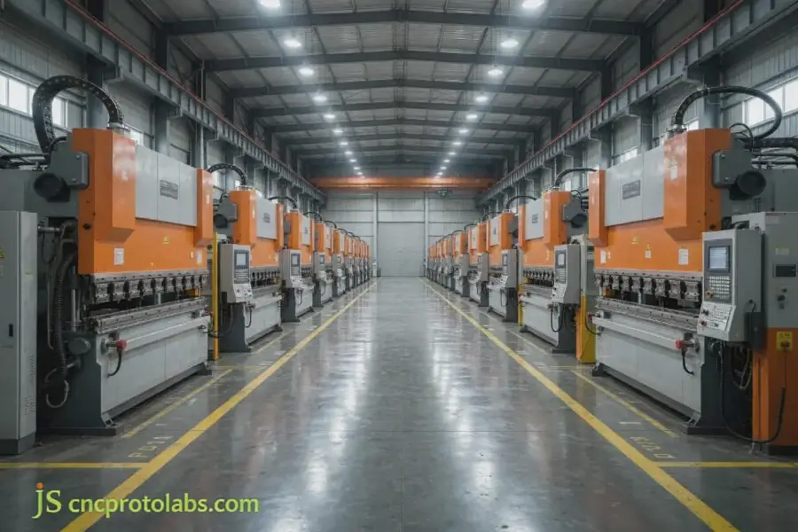
Figure 3: Worker operating press brake for air bending and bottoming tolerance rules.
How to Fix Springback Errors in Sheet Metal Fabrication?
Fixing springback errors in sheet metal fabrication is done in combination with overbending, bottoming, and dwell timing, which is the reason. Manual hammer-forming removal contributes to high repeat accuracy. JS Precision services get scrap down to 2.1%.
Correcting springback errors in sheet metal fabrication
The new procedure comprises three phases:
- Measuring springback angle;
- Adjusting the punch depth (e.g. 92° preset to 90°);
- Adding 1.0 s to the holding pressure.
Precision sheet metal fabrication services by JS Precision
Compensation varies with the materials. JS Precision database holds 1200+ calibration batches: 1.5° for AL5052-H32, 2.0° for SPCC, and 2.5°–3.0° for 304 stainless steel. Combining different control methods, DFM review, compensation tables, CNC optimization, CMM verification have decreased the number of scrap to 2.1% from 8–16% through 200+ projects.
Facing complex springback challenges on your robotics or automation parts? Talk to Engineer today to implement our precision compensation program and secure ±0.05 mm tolerances!
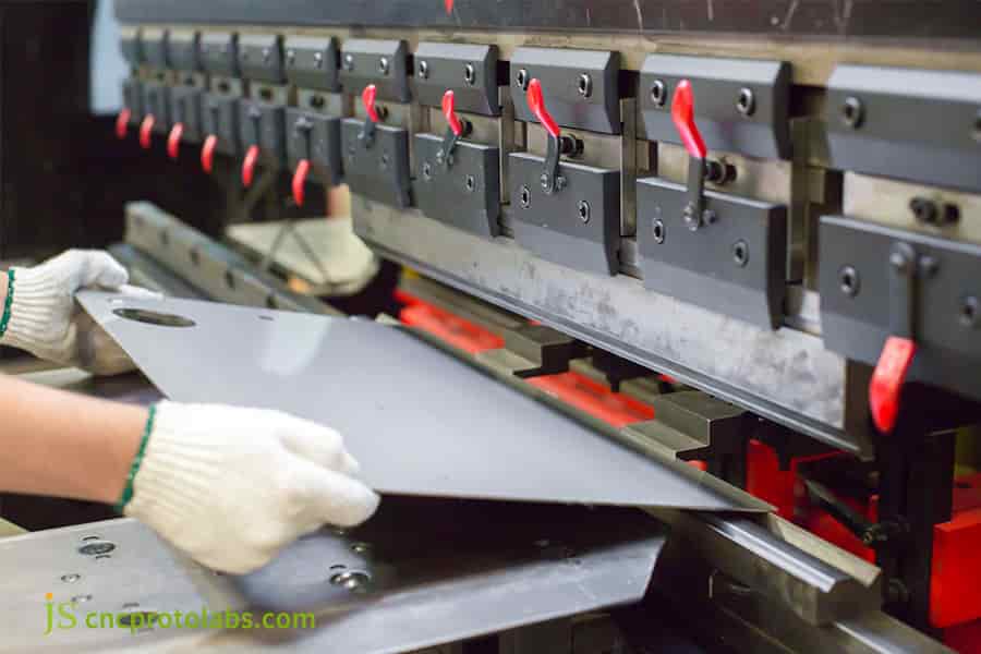
Figure 4: Press brake machines in fabrication workshop for fixing springback errors.
JS Precision Precision Sheet Metal Fabrication for Robotics Base: Bend Defect Elimination
A European leader in industrial robotics approached JS Precision with a critical issue: their multi-degree-of-freedom base structures suffered from 16% assembly scrap due to flange angle deviations.
Challenge
The famous team from the R&D division of an important industrial robot manufacturer in Europe entrusted some multi-Degrees-Of-Freedom base bending structures (made of material AL5052-H32, with a nominal thickness 2.0 mm) to their supplier. Yet, the main supplier just continued with the usual practice, used the default K-factor 0.44 in the CAD system for material cutting and carried out air bending without compensating for 2° elastic springback. After finishing the bending operation, the tolerance of the flange distance accumulated exceeded ±0.25 mm, there was interference in the servo motor positioning holes, rework rate in the assembly plant reached up to 16%, and the time to get the first sample out was 10 days.
The Solution
After our senior sheet metal engineering team took over, they fully implemented a DFM (Design for Manufacturing) refactoring:
- By doing physical tensile and bending tests, the original K-factor for an unfold was adjusted from 0.44 down to 0.38. Apart from that, a rectangular process tear groove of 2.5 mm depth was made to remove corner stress.
- The bending method was switched from traditional air bending to bottoming lower precision die calibration.
When doing the first trial bending, a 0.15 mm micro-stress crack showed up on the outer edge of the flange bend because the cold-rolled grains of the raw material ran parallel to the main bending line. The engineer at hand turned the blank over at that spot and made bending line cross the grain direction perpendicular (90°), which helped in eliminating stress cracking. Also, an 8V (16 mm) precision lower die was chosen which ensured complete elimination of stress crack.
The Results
- The flange forming tolerance is strictly and consistently kept within the fine tolerance range of ±0.05 mm.
- Servo mounting hole assembly defect rate decreased much from 16 to 2.1% .
- Absent of secondary manual straightening the overall bending cost per piece is slashed by 26%.
- The total cycle time covering from the sample to the large quantity order is brought down from 10 days to 6 days (delivery time reduced by 40%).
Hidden Value
The batch of components fully complies with the ISO 2768-m tolerance level and has passed the dynamic fatigue durability test under high-frequency industrial vibration environment.
Data Source: JS Precision Robotics Precision Component Engineering Optimization Archive (Project #ROBOT-2026-309, sample size >1,200 batches)
FAQs
Q1: Why do sheet metal bend angles spring back after pressure release?
This occurs because the residual elastic strain, which was formed during the bending operation, still wants to restore itself. JS Precision deals with this by presetting 1° to 3° of overbend and performing bottoming calibration on CNC press brakes.
Q2: How does an improperly set K-factor lead to completed flanges being longer than the drawing specifies?
In most cases, a K-factor is based on theoretical values that predict less than the actual extent of plastic deformation. For cold-rolled alloys, JS Precision applies a more accurate 0.38 K-factor, ensuring that the flange tolerance stays within ±0.05 mm.
Q3: What is the cause of tearing along the edges when the part borders are bent at or near 90 degrees?
Lack of bend reliefs results in stress concentration. To avoid tears, we add 2.5 mm-deep reliefs (depth sheet thickness + 0.5 mm) and follows the ASME Y14.5 standards.
Q4: How does raw sheet thickness variance distort bend angle consistency?
Slight variations in the sheet's thickness, up to ±0.05 mm, affect the contact geometry inside the V-die. To prevent this, we employ batch thickness compensation and reduces the scrap rate to only 2.1%.
Q5: Why is air bending more prone to tolerance errors than bottoming?
Air bending depends on stroke penetration, which makes it very sensitive to any change in material properties. That's why we employ bottoming for mating surfaces, keeping the tolerance locked between ±0.05 mm.
Q6: What is the optimal V-die opening ratio for precision sheet metal bending?
A V-die opening of 8 times the material thickness (8V) is the industrial standard. At JS Precision, 8V dies are always matched precisely with the punch radius, which results in no stress marks or cracks on the metal.
Q7: What impact can grain direction have on the least possible bend radius?
Bending parallel to the material grain gives rise to orange-peel type cracking. JS Precision carefully nest parts so that bends are done across grain at about 90°, usually exactly 90°, to avoid breaks.
Q8: What benefit do we gain by carrying out DFM at an early stage for sheet metal drawing precision?
Earlier DFM allows setting correct bend deductions and reliefs for different materials and bend angles. Our 2-hour expedited DFM service reduces trial time by 40% and also stops rework costs.
Summary
Bending misalignment is a physical manifestation of the interplay of multiple factors, including material properties, mold design, and springback. During the design phase, the default K-factor of 0.44 should be abandoned, a dynamic springback compensation model should be established, and tear grooves of ≥2.5 mm should be standardized to prevent tolerance stacking.
Don't let bending inaccuracies delay your production line. Get a Free Quote today and let JS Precision deliver precision sheet metal fabrication with guaranteed ±0.05 mm tolerances!
Disclaimer
The contents of this page are for informational purposes only. For JS Precision Services, there are no representations or warranties, express or implied, as to the accuracy, completeness, or validity of the information. It is the buyer's responsibility to identify specific technical requirements and request a formal parts quotation. Please contact us for more information.
Resource

