 English



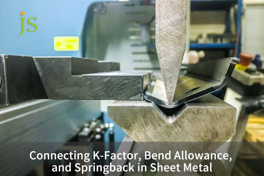

In precision sheet metal manufacturing, the K-Factor is a geometric dimensionless constant describing the proportion of neutral layer displacement during material deformation. Bend allowance is the actual arc length unfolding compensation calculated based on the K value; and springback is the angle opening caused by elastic recovery after the forming load is removed. These three factors, along with sheet thickness, inner corner radius, and material elastic modulus, form a complete closed loop for predicting unfolded dimensions.
Core Answer Summary Table
The accuracy of the dimensions of the unfolded sheet metal mainly comes from the computation of unfolding compensation based on neutral layer offset and the geometric correction of the material unloading springback through overbending.
|
Core Parameter |
Physical Definition |
Typical Engineering Range |
Core Control Objective |
|---|---|---|---|
|
K-Factor (K) |
Ratio of neutral layer depth to sheet thickness (t/T) |
0.30 to 0.50 (Nominal 0.44 for mild steel) |
Determine the location of the neutral layer with zero tensile/compressive stress. |
|
Bend Allowance (BA) |
Developed arc length of the material's neutral layer along the bend |
Calculated based on inside radius, sheet thickness, and bend angle |
Determine the flat pattern blank size for CAD/CAM. |
|
Springback (△θ) |
Elastic angular recovery after punch pressure is released |
0.5° to 4.0° (depending on material yield ratio) |
Determine tooling design and overbend compensation. |
Sources: General tolerances per ISO 2768; cold-bending K baselines per DIN 6935.
What Is the Bending Calculation for Sheet Metal Neutral Axis?
Sheet metal bending calculations determine the developed flat blank length by tracking the neutral axis. During plastic deformation, the neutral axis shifts inward from the material centerline (0.50T) toward 0.33T to 0.44T as the inside bend radius tightens relative to thickness. Calculating exact bend allowance requires factoring in the inside radius, bend angle, sheet thickness, and dynamic K-factor to prevent dimensional expansion errors after forming.
Microstrain distribution of external tension and internal compression
- Outer surface gets stretched under biaxial tensile strain: The material located at the bending outer side is stretched, and so, the spacing between the fibers is increased. Strain value shows an increasing gradient through the steel plate thickness.
- Inner surface is strained in biaxial compression: inner material is compressed, and shortened, because of this neutral layer (i.e. The transition layer where no stress and strain are present) gradually shifts inward.
- Neutral axis shift occurs dynamically: as the ratio of the bending radius to the sheet thickness (R/T) decreases the neutral axis moves from 0.50 T to 0.33 T, so the unfolding length is changed. This occurrence is called the neutral axis shifting under plastic deformation and it is one of the major variables whose quantitative determination is essential in bending calculation for sheet metal.
Standard expansion calculation formula and parameter analysis
Core formula:
BA=(π/180)×A×(R+K×T)
Where A is the bending angle, R is the inner radius, and T is the plate thickness.
- Parameter units: All parameters must include standard units, such as T=2.0 mm, R=2.0 mm, A=90°.
- Engineering applications: Getting the position of the neutral layer precisely can directly affect and change the blanking size for a flat plate. That means, laser cutting tolerance specifications must be taken into consideration to make sure the laser cutting kerf width agrees with the unfolded length.
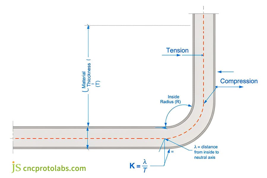
Figure 1: Schematic diagram of strain distribution in sheet metal section.
What Is the Difference Between Bend Allowance and Bend Deduction?
Bend allowance adds the exact length of the neutral axis arc to the flat lengths of the two flanges. Conversely, bend deduction subtracts the geometric apex expansion from the sum of the overall outside dimensions. Both methods yield identical flat patterns when calibrated against verified bending allowance charts, differing only in whether CAD operators measure from internal tangent points or external virtual apexes.
Geometric datum differences between addition logic and subtraction logic
- Bend allowance (BA): the neutral plane arc length is simply added to the flange lengths; the measurement reference is at the inside tangent point.
- Bend deduction (BD): the imaginary corner swelling (OSSB) that was subtracted is then compared with the outer lines added together, taking as a measuring reference an outer invisible intersection point.
- Formula identity: When BA and BD are both set by the same K-factor they yield exactly the same developed size. Being aware of the what is the difference between bend allowance and bend deduction will assist designers to select a suitable CAD unfolding method.
Measurement tolerance effects of 90° and obtuse/acute angle bends
- 90° bend: The conversion relationship between BA and BD is BD=2×(R+T)-BA, which has the lowest error sensitivity.
- Obtuse angle bends: Outer contour measurements are easily amplified by angular deviations, so BA additive logic is recommended.
- Acute angle bending: It is difficult to locate the inner tangent point. The BD subtraction logic can more easily ensure the centering of the mold.
Limitations of the Bending Compensation Quick Reference Table
- Dependence on lower die opening (V width): For the same material, the K value will deviate by ±0.03 under different V widths. The quick reference table must indicate the corresponding V width.
- Punch tip radius: BA reference value when R_punch=1.0T. If R_punch changes, it needs to be recalibrated.
- Dispelling common misconceptions: Typical air bend formulas apply only to the general-purpose tables, while the bottom bends need an extra compensation of 0.04-0.08. Although there might be different kinds of bend deduction standards adopted by various sheet metal manufacturing businesses, the essential idea of bend deduction remains unchanged. A calibration should be carried out by consulting an authoritative bending allowance chart.
|
Material |
Thickness T (mm) |
Recommended Punch Radius R (mm) |
Empirical K-Factor |
90° BA (mm) |
90° BD (mm) |
|---|---|---|---|---|---|
|
SPCC Cold Rolled Steel |
1.0 |
1.0 |
0.44 |
1.93 |
2.07 |
|
SPCC Cold Rolled Steel |
2.0 |
2.0 |
0.42 |
3.82 |
4.18 |
|
5052-H32 Aluminum |
1.5 |
1.5 |
0.41 |
2.84 |
3.16 |
|
304 Stainless Steel |
2.0 |
2.0 |
0.37 |
3.56 |
4.44 |
|
6061-T6 Aluminum |
3.0 |
3.0 |
0.39 |
5.21 |
6.79 |
According to ASME Y14.38-2020, standard for sheet metal bending allowance calculation and geometric dimensioning ensures consistent flat pattern development.
When checking the tolerance of the speed chart in school, you can refer to JS Precision's sheet metal tolerance guide to confirm that the forming dimensions comply with ISO 2768-m.
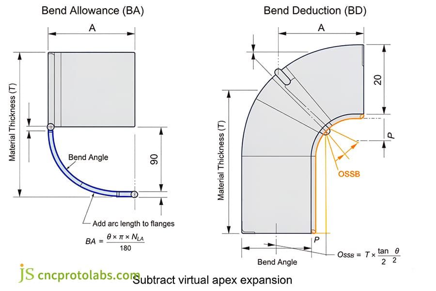
Figure 2: BA and BD measurement geometry diagram.
How Does Air Bending Sheet Metal Counteract Material Springback?
Air bending counteracts material springback by intentionally overbending the workpiece beyond the target angle, allowing the part to relax to its design dimension upon punch retraction. High-yield metals like 6061-T6 aluminum exhibit pronounced springback up to 4° due to their elevated yield-to-modulus ratio, requiring adaptive stroke depth programming and precise V-opening selection to stabilize mechanical bend allowance.
Differences in springback mechanisms between free bending, bottom bending, and fixed bending
- Air bending: The work piece is only in contact with the punch and the bottom die shoulder, so it produces a large springback after unloaded which needs a bending compensation. In air bending sheet metal process, the punch depth control the springback compensation.
- Bottoming: as the high tonnage extrusion leads to the material freely flowing to adopt the shape of the mold, the springback is decreased to 0.5°–1.0°, but the K value shifted positively by 0.04–0.08.
- Coining: Localized plastic flow atthe tool/part interface totally removes elastic strain, producing negligible springback, but causes 30% higher die wear.
Physical law governing yield strength ratio (σ_y/E) and rebound angle
- Yield strength σ_y: The critical stress at which a material begins to undergo plastic deformation, measured in MPa.
- Elastic modulus E: The ability of a material to resist elastic deformation, measured in GPa.
- Elastic strain recovery modulus ratio ( σ_y/E): The higher the ratio, the more severe the springback. For example, 304 stainless steel with σ_y/E = 0.40 exhibits a springback of 2.0°–3.0°. This parameter is a core indicator for predicting changes in bending allowance after unloading.
Grain orientation and microcrack suppression in high-hardness aluminum (6061-T6)
- Bending along the rolling direction plasticity decreases, the K value drops by as much as 0.02-0.03, and springback angle reaches up 3.0°-4.0°.
- Bending perpendicular to the rolling direction although ductility is fairly good, springback angle 2.5°-3.5°. Though, to prevent micro-cracks, it is required that controlling R/T ≥ 1.5.
- The over-bending compensation strategy: Employ an 86°-87° punch, and a V=8T lower die, and use the CNC system to dynamically correct the bottom dead point. Because of the large springback property of bending 6061 t6 aluminum, the angle set by the punch over-bending should be within the scope of 86° to 87°.
|
Alloy & Temper |
Yield Strength σ_y (MPa) |
Elastic Modulus E (GPa) |
σ_y/E ×10⁻³ |
90° Air Bending Springback (△θ) |
Recommended Overbend Angle |
|---|---|---|---|---|---|
|
SPCC Cold Rolled |
370 |
210 |
1.76 |
0.5°-1.0° |
89.0°-89.5° |
|
5052-H32 Aluminum |
172 |
70 |
2.46 |
1.5°-2.5° |
87.5°-88.5° |
|
6061-T6 Aluminum |
276 |
70 |
3.94 |
2.5°-4.0° |
86.0°-87.0° |
|
304 Stainless Steel |
205 |
200 |
1.03 |
2.0°-3.0° |
87.0°-88.0° |
|
C26000 Brass (Half Hard) |
300 |
110 |
2.73 |
1.0°-2.0° |
88.0°-89.0° |
According to AWS D1.1/D1.1M:2020, structural welding code requirements indirectly influence bend allowance calculations in fabricated assemblies.
Complex bending and forming processes require systematic knowledge; it is recommended to consult the precision metal fabrication guide for complete process guidance.
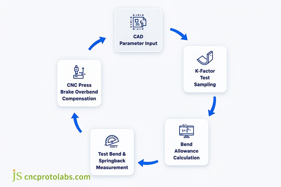
Figure 3: The engineering closed-loop flowchart of CAD drawing parameter input → K-Factor test sampling calibration → bending compensation calculation → test bending rebound angle → CNC bending machine punch stroke over bending compensation.
FAQ
Q1: How to calculate k-factor in sheet metal bending?
The exact value is calculated by reverse bending using a sample test. Prepare a standard sheet metal specimen with a known thickness T, bend it 90° and let it cool. Measure the lengths of the two outer flanges and the inner corner radius R. Based on the measured total length, deduce the true BA, and then substitute it into the formula K=[(180×BA)/(π×90)-R]/T to calculate the precise value.
Q2: Why does sheet metal springback occur after bending?
Bending metal involves the simultaneous occurrence of elastic and plastic deformations. Plastic flow is happening in the inner and outer areas, far from the yield point. Still, a small volume of metal near the neutral layer is not deforming plastically. It deforms elastically only. The bending moment is released when the stamp is removed, the elastic stress is instantly released, causing more bending and flange springback.
Q3: How do you compensate for springback in air bending?
A bending angle greater than the desired one is used during the air bending operation. The punch press moves slightly deeper, thereby bending the part below the reference angle by a certain amount (like bending a 90° piece to 88° first) and letting material naturally spring back to 2° and fall to the design nominal angle. At the same time, use an 85° or 88° punch together with a V-die for shape.
Q4: What k-factor should be used for aluminum bending?
The K-factor of aluminum alloys depends on their annealing state and alloy composition. For soft-annealed aluminum (such as 1100-O or 5052-H32), the engineering recommendation for standard bending is 0.40 to 0.44; while for precipitation-hardened high-strength aluminum alloys (such as 6061-T6), due to their high plastic flow resistance and intense internal compression, the actual effective K-factor usually deviates between 0.38 and 0.42.
Q5: Can bend deduction be a negative number?
In most cases the bending deduction (BD) will be a positive number. But, if large-radius bending happens under extreme conditions (where the inner fillet radius R exceeds the five times the plate thickness T), the neutral layer arc length will definitely be longer than the distance from the extensions of the two virtual tangent apexes. Then the sum of the outer dimensions is a smaller number than the required true plate length. Under such conditions, the calculated BD will result in a negative one numerically.
Summary
This paper summarizes the synergistic closed loop of K-Factor, Bend Allowance, and Springback in sheet metal processing. The K-Factor determines the geometric position of the neutral layer, the unfolding compensation determines the flat plate size after punching and shearing, and the springback compensation determines the final physical forming accuracy of the bending machine die and bottom dead center control. The close integration of these three factors is the cornerstone for ensuring no assembly interference in various precision metal sheet metal parts. When discussing actual factory production and bending forming control, custom sheet metal bending services can be used to translate theory into stable mass production.
Designing precision bent parts with tight tolerance geometrics requires rigorous tool selection and bend sequence planning. To understand how custom tooling and press brake calibrations maintain angular accuracy across production runs, engineers can explore custom sheet metal fabrication capabilities to review advanced forming standards and design guidelines.
Disclaimer
The contents of this page are for informational purposes only. For JS Precision Services, there are no representations or warranties, express or implied, as to the accuracy, completeness, or validity of the information. It is the buyer's responsibility to identify specific technical requirements and request a formal parts quotation. Please contact us for more information.
Resource

