 English



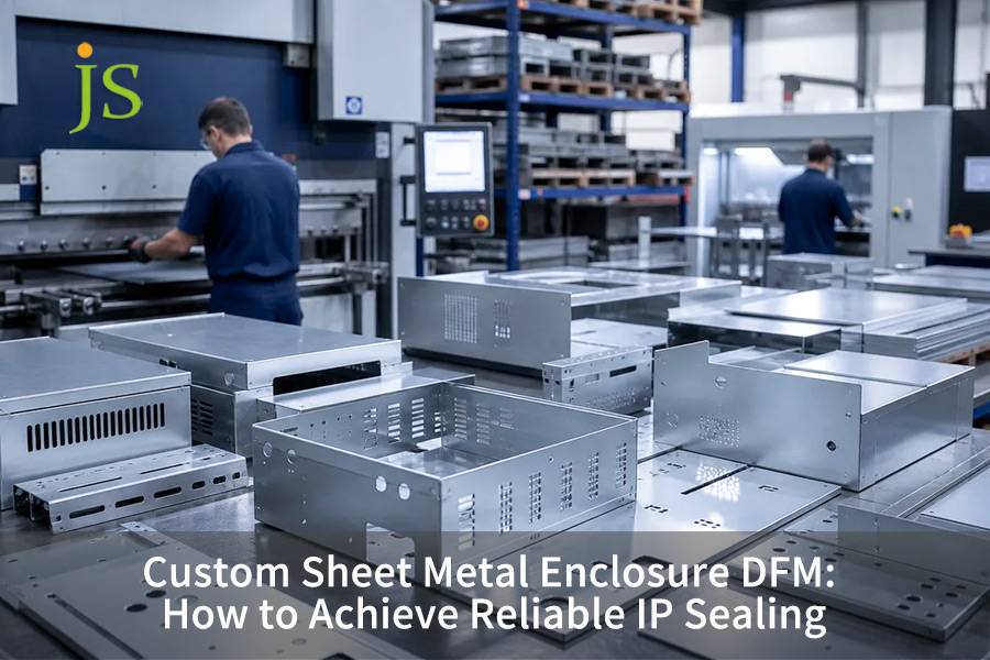

Custom sheet metal enclosure IP sealing depends on three variables: 25%–35% gasket compression, rigid flange geometry, and fastener pitch tight enough to prevent panel bowing. Sheet metal introduces springback and deflection, so material yield strength must be considered alongside continuous TIG welds and surface finishing to reach IP65–IP67.
Core Takeaway Table: IP Rating Enclosure Design
What the IP codes mean: The first digit covers solid ingress (5 = dust-protected, 6 = dust-tight); the second covers water. IP65 resists low-pressure water jets, IP66 resists powerful jets, and IP67 survives temporary immersion in 1 m of water for 30 minutes. Each step up roughly triples the sealing demand on flange stiffness and fastener pitch.
|
IP Rating Standard |
Core Failure Mode |
Recommended Sealing Solution |
Sheet Metal Flange Key Structure & Tolerance |
Fastener Pitch Limit (mm) |
|---|---|---|---|---|
|
IP54 (Dust/Splash) |
Corner burr cutting, panel micro-bowing |
Closed-cell EPDM sponge rubber adhesive strip |
Single-fold flange, surface flatness ≤ 0.5 mm |
≤ 120 (t ≥ 1.2 mm) |
|
IP65 (Low-pressure jet) |
Bend springback causes inter-screw lift-off |
FIPFG continuous polyurethane in-situ foaming |
U-channel guide groove, unfold angle tolerance ±0.5° |
≤ 75 (t ≥ 1.5 mm) |
|
IP66 (Heavy seas/high-pressure) |
Weld micropores, screw washer seepage |
Molded fluorosilicone / solid silicone ring |
Double labyrinth flange stop, sealing datum flatness ≤ 0.2 mm |
≤ 50 (t ≥ 2.0 mm) |
|
IP67 (Temporary immersion 1m) |
Cavity negative pressure suction, coating delamination |
Vulcanized one-piece continuous silicone gasket |
CNC full-perimeter continuous TIG pore-free weld + air-tight test |
≤ 40 + countersunk press rivet column seal |
The key to achieving a high level of protection is to use double folded rigid flanges to counteract the bending of the plate under the fastening preload force, ensuring that the uniformity of compression throughout the entire circumference is within 10%.
According to IEC 60529:2013, Degrees of protection provided by enclosures (IP Code) defines the water jet pressure thresholds at 30 kPa for IPX5 and 100 kPa for IPX6, validating the dynamic load limits in this table.
How to Set Ingress Limits for IP Rating Enclosure Design?
An IP rating enclosure design relies on matching target operating environments to specific sheet metal mechanical boundaries including yield strength, bend radii, and fastener clamping forces. Achieving IP65 prevents dust entry and resists 12.5 L/min water jets at 30 kPa, whereas IP66 withstands 100 L/min heavy seas at 100 kPa. These forces easily distort thin sheet metal panels if the structural stiffness and joint seals are improperly calculated.
IEC 60529 Protection Class - Boundary Analysis of Dynamic Hydraulic Load
- IP65 testing uses a 6.3 mm nozzle at 12.5 L/min and 30 kPa for 3 minutes. This imposes a local peel load of roughly 0.03 MPa on the panel — the starting point for any stiffness calculation in IP rating enclosure design.
- IP66 testing uses a 12.5 mm nozzle at 100 L/min and 100 kPa. The panel must resist a peel load of 0.10 MPa, far above the bending limit of an unreinforced thin panel.
Comparison of Elastic Modulus and Bending Strength of Common Sheet Metal Materials
- SPCC has an elastic modulus of 200 GPa and a yield strength of 210 MPa.
- 5052-H32 aluminum alloy has an elastic modulus of 70 GPa and a yield strength of 215 MPa.
- 304 stainless steel has an elastic modulus of 193 GPa and a yield strength of 240 MPa.
A sound IP-rated enclosure design accounts for all three material properties when defining the sealing surface.
Primary constraints of development tolerance and forming tolerance on the sealing datum surface
Laser cutting tolerance is ±0.1 mm, bending angle tolerance is ±0.5°, and the flatness of the gasket mounting datum must be ≤ 0.2 mm.
On a 2025 outdoor energy storage enclosure project, JS Precision reduced the bending springback compensation from 1.5° to 0.8°, which raised the first-pass rate for sealing surface flatness from 82% to 97% — clear evidence that tolerance allocation is indispensable to IP rating enclosure design.
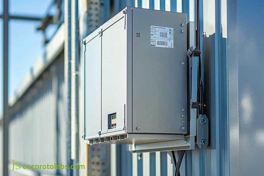
Figure 1: Metal electrical enclosure mounted on wall.
How Does Flange Geometry Prevent Sheet Metal Enclosure Gaps?
Sheet metal enclosure DFM minimizes ingress gaps by replacing flat edge contacts with formed flanges, hemmed stiffeners, and nested return bends that increase edge rigidity by over 300%. Flat sheet metal edges buckle between fastener intervals under bolt torque. Incorporating a 90-degree internal return bend maintains uniform contact pressure against the sealing strip, preventing microscopic leakage paths.
Assessment of bending springback and panel arching
- The bending moment of inertia of a single right-angle folded section is 1.2 × t³/12; for a folded dead edge, it is 4.8 × t³/12; and for a multi-fold nested guide groove, 6.5 × t³/12. The rigidity increase exceeds 300%. Such a remarkable feature will enable the manufacturing processes to produce custom sheet metal enclosure free of leakage.
- Springback is 2°–3° for 5052-H32 aluminum and 1°–2° for 304 stainless steel, so springback pre-compensation must be built in at the tooling design stage.
Minimum flange height geometric constraints and sealing groove section parameters
- The minimum flange height shall be such that H ≥ 4t + R to prevent bending interference from causing deformation, sealing grooves. This limitation should be kept in mind for each custom sheet metal enclosure.
- Size the seal groove to 1.2× the gasket's free width and 0.8× its free height. That yields a nominal 20% compression while leaving room for the gasket to expand laterally without overflowing the groove.
Principle of metal hard contact limit mechanism
A rigid flange acts as a physical hard stop, creating metal-to-metal contact that caps compression at 35% and protects the gasket from crushing. The contact plane must be flat within 0.1 mm, which is what gives the enclosure its long-term sealing durability.
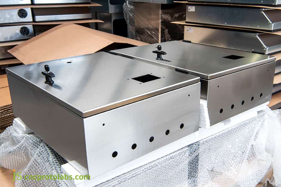
Figure 2: Sheet metal enclosure boxes with flange design.
How to Select Enclosure Gaskets and Calculate Compression?
Sheet metal enclosure gasket design requires maintaining a continuous compression deflection between 25% and 35% for closed-cell sponges and 15% to 25% for solid elastomers to achieve durable IP66 sealing. Compression below 20% leaves intermittent micro-voids, while over-compression beyond 50% triggers rapid compression set and premature degradation.
Comparison of Performance and Compression Parameters of Common Chassis Sealing Strips in Engineering
|
Sealing Material |
Shore Hardness |
Recommended Compression Ratio |
Service Temp Range |
Applicable Sheet Metal Structure |
|---|---|---|---|---|
|
Closed-cell EPDM Sponge |
Shore 00 40–50 |
25%–35% |
-40°C to +120°C |
Single-fold flange, flat edge |
|
FIPFG PU Foam |
Shore A 25–35 |
20%–30% |
-40°C to +85°C |
U-channel guide groove, labyrinth stop |
|
Molded Silicone Rubber |
Shore A 50–60 |
15%–25% |
-60°C to +200°C |
Double labyrinth flange, precision stop |
According to ASTM D1056-20, Standard Specification for Flexible Cellular Materials — Sponge or Expanded Rubber, and ASTM D395, Standard Test Methods for Rubber Property — Compression Set, the compression deflection and compression set limits for closed-cell EPDM are defined, validating both the 25%–35% compression ratio and the ≤15% compression set criterion in this section.
FIPFG in-situ foaming eliminates capillary penetration paths, which makes it the most reliable route to IP66. Compared with die-cut sheet metal enclosure gaskets, the FIPFG process directly determines sealing system reliability, because it removes corner splices and shear gaps entirely.
At 25% compression, closed-cell EPDM exerts a counter-force of about 0.15 MPa, FIPFG polyurethane foam about 0.08 MPa, and molded solid silicone about 0.25 MPa. A well-designed sheet metal enclosure gasket balances this counter-force against flange stiffness.
Compression Set Criteria Under Wide Temperature Cycling
- The compression set of the material must be ≤ 15% under a wide temperature cycling range of -40°C to +85°C.
- In JS Precision's 2025 energy storage enclosure project, FIPFG polyurethane foam measured 12% compression set, versus 22% for conventional EPDM adhesive strips — clear evidence of how much material selection matters in sheet metal enclosure gasket design.

How Does Fastener Pitch Prevent Sheet Metal Panel Bowing?
IP sealing sheet metal performance depends on calculating fastener pitch using panel bending beam deflection equations to ensure displacement between adjacent screws does not exceed 0.05 mm under target compression loads. Placing fasteners excessively far apart results in visible center span lift-off, whereas clustering fasteners below 25 mm drives up production costs and weakens sheet metal edges.
Derivation of the formula for deflection deformation of the fixed beam at the edge of the panel:
The panel between the two bolts is abstracted as a fixed beam, with a maximum mid-span deflection:
δ = (q × L⁴) / (384 × E × I)
When δ exceeds 0.05 mm, the sealing contact line peels off. Keeping the span below these critical values requires the dimensional control of a precision sheet metal fabrication partner.
Quick reference of maximum screw spacing and allowable mid-span deformation for different sheet metal materials/thicknesses:
|
Material & Thickness |
Recommended Pitch (mm) |
Max Allowable Deflection (mm) |
Compression Load (N/m) |
Edge Shear Margin |
|---|---|---|---|---|
|
1.2 mm SPCC Steel |
50–65 |
≤ 0.05 |
120 |
1.8× yield |
|
1.5 mm 5052 Aluminum |
45–60 |
≤ 0.05 |
100 |
1.5× yield |
|
2.0 mm 304 Stainless |
70–90 |
≤ 0.05 |
150 |
2.0× yield |
According to ISO 898-1:2013, Mechanical properties of fasteners made of carbon steel and alloy steel — Part 1, the property classes defined there determine a fastener's clamp load capacity, which is the input to the pitch calculations in this table.
Blind-hole press-fit studs do not penetrate the enclosure wall, so they offer the highest airtight reliability and are the preferred choice for IP66/IP67 enclosures. Correct hole preparation and installation torque are what turn this design choice into verified airtight reliability.
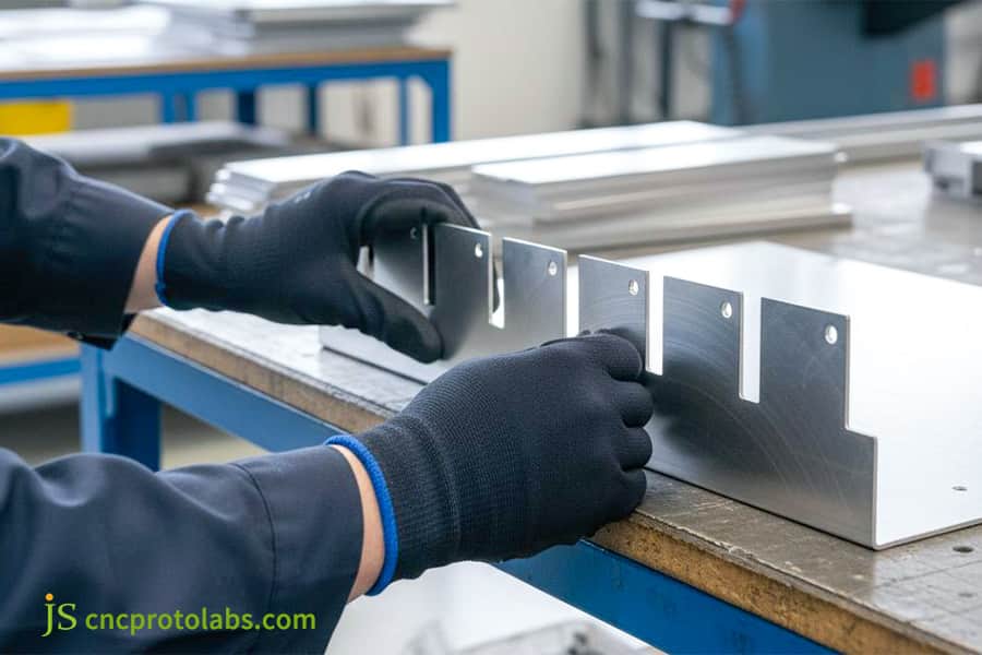
Figure 3: Worker assembling sheet metal bracket parts.
How Do Corner Reliefs and Continuous Welds Stop Water Leaks?
Precision sheet metal fabrication service resolves corner seal failures by engineering tear-drop or circular corner reliefs matched with 100% continuous robotic TIG welding to fully seal multi-plane intersections. Standard punch presses leave intersecting slit gaps at 90-degree corner joints. Precision DFM practices specify laser-cut overlapping tabs that provide structural backing material, eliminating weld burn-through and internal porosity.
The Influence of Cut Corner Geometry on Air Tightness at the Intersection of Three-Sided Bending
The square hole chamfer leaves a 0.3–0.5 mm junction hole, while the tear angle yields a capillary slit measuring 0.5–0.8 mm in width. When laser blanking and bending are coordinated to the same datum, a 0.8 mm tongue overlap completely closes the junction hole.
The fundamental distinction between spot welding vs continuous argon arc welding
- Spot welding leaves microscopic capillary gaps between weld nuggets.
- Continuous TIG welding produces an unbroken seam around the full perimeter, eliminating the capillary paths that spot welds leave behind.
Only robotic or consistently programmed TIG cells can maintain the heat input and flange flatness this requires.
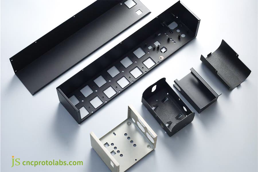
Figure 4: Various sheet metal enclosure components laid out.
How Does Powder Coating Thickness Affect Sheet Metal Tolerances?
Sheet metal fabrication service quality hinges on accounting for powder coating film build-up (typically 60 to 120 μm) on critical sealing lands. Unmasked powder overspray creates rough contact planes that induce localized shear on elastomeric gaskets and cause rapid fastener clamp-load relaxation over operational thermal cycles.
Electrostatic edge build-up pushes coating thickness at bends to as much as 120 μm, causing assembly interference of 0.1–0.15 mm. Masking the seal land before coating is the only reliable way to prevent this — that is, the coating lifting the sealing surface.
As the coating relaxes through viscoelastic creep, the initial fastener preload is lost and clamp load drops by more than 30% within 6 months. Masking the seal land and controlling film build reduce that loss to as little as 8%.
Which Leak Testing Methods Verify IP Enclosure Performance?
Custom sheet metal enclosure integrity is verified using pressure decay leak testing and calibrated water spray chambers according to ISO 20653 and IEC 60529 protocols. Automated air decay instruments measure interior pressure drops across 30 to 60 seconds at 20 to 50 kPa, detecting microscopic weld fissures down to 0.1 sccm before units advance to high-volume assembly.
IP65/IP66 Type Test Water Spray Condition and Production Line Pressure Drop and Air Tightness Leak Detection (Delta-P) Test Parameter Matrix Table
|
Test Parameter |
IPX5 Spray Test |
IPX6 High-pressure Jet |
Production Delta-P Test |
Acceptance Criterion |
|---|---|---|---|---|
|
Nozzle Diameter (mm) |
6.3 |
12.5 |
N/A (air probe) |
Per IEC 60529 |
|
Water Pressure (kPa) |
30 |
100 |
20–50 |
Pressure drop ≤ 0.5 kPa |
|
Flow Rate (L/min) |
12.5 |
100 |
N/A |
N/A |
|
Test Duration (min) |
3 |
3 |
0.5–1.0 |
Stable reading |
|
Leak Rate Limit (sccm) |
0 (no ingress) |
0 (no ingress) |
≤ 0.1 |
Pass |
Per IEC 60529:2013, IP67 requires no water ingress after 30 minutes of immersion at 1 m. The production pressure-decay methodology below follows ISO 20653:2023 as applied to sealed enclosures, and validates the 0.1 sccm detection threshold in this table.
Dual-track testing specifications:
Type testing passes when no water enters the enclosure during the 3-minute spray test and the interior passes inspection after drying. The production-line differential pressure (Delta-P) test passes when the part is pressurized to 30 kPa, held for 30 seconds, and the pressure drop is ≤ 0.5 kPa. These two tracks verify IP rating enclosure design and demonstrate control of mass-production consistency.
Case Study: How JS Precision Fixed Leaks in an IP66 Enclosure
JS Precision engineered an outdoor 5052-H32 aluminum battery storage enclosure meeting IP66 standards by redesigning a leaky flat-flange layout into a stiffened labyrinth seal profile with continuous CNC TIG corner joints. The initial prototype failed water spray tests due to 1.8 mm edge bowing between screw points. JS Precision reduced fastener pitch to 50 mm, optimized bend reliefs, and automated FIPFG silicone dispensing, achieving a 99.8% first-pass leak-test rate across 1,200 production units.
Challenges faced by customers
An outdoor battery enclosure, made from 2.0 mm 5052 aluminum alloy, 800 × 600 × 300 mm, of a European energy storage system integrator, underwent a severe water leakage incident in a IP66 high-pressure water column test. The first unit of the bespoke sheet metal enclosure had a single right-angle flange with manually applied adhesive foam strips on the joint. Under the 100 kPa jet, the door panel — fastened at 150 mm intervals — bowed upward locally between screws by 1.8 mm. And, small defect areas were found on the manually welded corners.
JS Precision Solution
- Flange section stiffness upgrade: The straight flange is redesigned into a double-folded inward-folding flap stop structure. This not only brings 4.2 times increase in bending section modulus, but also restricts the middle section compression deformation to ≤ 0.05 mm.
- Auxiliary laser blanking corner compensation: The unfolding punching layout diagram is re-designed; a 0.8 mm jointed tongue is added to the corner intersection line for eliminating capillary dark lines that appear after the bending operation.
- TIG Full welding with CNC robot: A total robotic welding is conducted at the corner closure, using a fully automatic six-axis robot. The welding thermal deformation is controlled with water-cooled copper fixtures. Flange flatness around the full perimeter was held within 0.2 mm.
- Robotic FIPFG dispensing: Manual gasket application was replaced by a fully automated cell that dispenses two-component silicone directly onto the part, with a continuous R3 mm corner radius that eliminated gaps at the splices.
- Pitch reduction and blind fastening: Fastener pitch was reduced to 50 mm, and the fastening points were changed to blind press-fit nuts applied from the exterior, leaving no through-holes. JS Precision implemented these process parameters on the production line without deviation.
Review of failure experiences and lessons learned
In the first powder-coated pilot batch, no dedicated fixture was used to mask the seal groove and the dispensed gasket. About 100 μm of overspray reduced the peel strength between the foamed silicone and the substrate by 50%, causing localized delamination during subsequent thermal shock cycling.
The engineering team then built a dedicated masking fixture that keeps the groove completely paint-free while maintaining a metal surface roughness of Ra ≤ 1.6 μm, which fully eliminated interface delamination. The key process upgrade was moving masking to the pre-coating stage, so the coating can no longer interfere with the sealing compression.
Final result
The redesigned enclosure passed IP66 type testing at an accredited third-party laboratory: no water ingress from any direction at 100 kPa. Across a production batch of 1,200 units, the first-pass leak-test rate reached 99.8%, and the customer's assembly-line leak-related rework fell by 35%.
Need help resolving leaks in outdoor enclosure prototypes or poor sealing in mass production? Contact the JS Precision engineering team for the same robotic FIPFG dispensing and continuous TIG welding solution, and get your enclosure through IP66 testing on the first try.
FAQs
Q1: What is the minimum sheet metal thickness required to maintain an IP65 rating?
When designing IP65 sheet metal enclosures, cold-rolled steel sheets should be ≥ 1.5 mm thick, and 5052 aluminum alloy sheets should be ≥ 2.0 mm thick. Sheets thinner than 1.2 mm are prone to arching and deformation between spans under bolt preload, leading to uneven pressure and leakage.
Q2: Why do standard spot-welded sheet metal seams fail IP66 water ingress tests?
Spot welds have microscopic capillary gaps which allow water to penetrate under the impact of a 100 kPa high-pressure water jet (equivalent to IP66 level certified). Only by doing 100% continuous TIG sealing welds could the highest level of sealing be ensured.
Q3: How does pour-in-place (FIPFG) gasket dispensing compare to traditional die-cut tape?
Pour-in-place (FIPFG) gasketing uses robotic dispensing of micro-cellular polyurethane to form a seamless, closed-loop bead. It eliminates the corner splices and shear-leakage defects inherent to die-cut tape, and typically raises gasketing throughput by up to 40%.
Q4: Can an enclosure achieve an IP67 immersion rating without precision machining?
Yes. The prerequisites are a deformation-resistant rigid flange, continuous TIG welding around the full perimeter, and a dense bolt layout. Together these let the silicone gasket hold a stable 30% compression. Every unit must also pass a pressure-decay leak test before shipment.
Q5: How do cable pass-throughs and gland plates preserve the overall IP enclosure rating?
Use IP66/IP68-rated waterproof cable glands mounted on flat, reinforced cover plates. Never place holes on or near a bend — doing so distorts the bend line and compromises the sealing fit.
Q6: What tolerance must precision bending maintain to ensure even gasket compression?
The CNC bending angle tolerance shall stay within ±0.5° while that of the flange sealing surface's flatness deviation shall be ≤ 0.2 mm. Any deviation more than 1° would result in the gasket being wedge-shaped and squeezed, giving rise to areas of insufficient compression and consequent leakage.
Q7: How does JS Precision verify IP sealing performance during low-volume prototyping?
JS Precision employs a high-precision differential pressure leak detector to perform 100% non-destructive airtightness screening, and is equipped with a water spray test chamber to perform IPX5/IPX6 tests, and uses a 3D scanner to verify the tolerance of the sealing surface.
Q8: How do fabrication volume and DFM design complexity affect custom enclosure pricing?
The unit price of the chassis depends on the full weld length, grinding time, adhesive dispensing path complexity, and base material type. Standard bent slots reduce costs by approximately 25% compared to manual welding. JS Precision provides a detailed DFM and cost quotation list based on 3D CAD models within 24 hours.
Summary
Achieving reliable IP sealing for customized sheet metal chassis hinges on eliminating microscopic deformations caused by cold bending and welding. This is achieved by increasing the section modulus through double anti-warping folds, utilizing beam bending mechanics to converge and tighten the bolt pitch, and combining this with laser lap compensation to eliminate chamfered voids—the fundamental approach to resolving leaks. Combined with scientific compression ratio calculations, coating masking, and airtightness testing, the chassis can be endowed with long-term durability.
Struggling with leaks in outdoor enclosure prototypes or poor sealing in mass production? Don't let minor DFM defects slow down your time to market. JS Precision boasts a team of experienced engineers and advanced CNC laser cutting, robotic welding, and fully automated foaming equipment. Send your 3D CAD drawings to our engineering team now, and we'll provide a complete sheet metal enclosure DFM assessment and quote within 24 hours, including airtightness analysis, stop optimization suggestions, and process planning.
Disclaimer
The contents of this page are for informational purposes only. For JS Precision Services, there are no representations or warranties, express or implied, as to the accuracy, completeness, or validity of the information. It is the buyer's responsibility to identify specific technical requirements and request a formal parts quotation. Please contact us for more information.
Resource

