 English



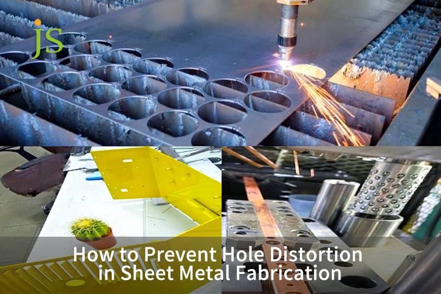

Sheet metal hole design therefore decides dimensional stability at the press brake, not at inspection. Uncontrolled hole distortion shows up downstream as hardware misalignment, stripped threads and assembly failure — failures that are cheap to prevent in CAD and expensive to fix on the line. Prevention combines three levers: predictive CAD offset compensation, dynamic lower-die selection (V-opening, polyurethane or rolling-bearing die), and process sequencing. Together they isolate the plastic strain zone so it never reaches the hole wall.
Key takeaways
- The rule: keep the hole edge D ≥ 2.5T + R from the bend line, where T is sheet thickness and R is the inside bend radius. Below that, the hole sits in the tensile strain field and goes oval.
- No room for spacing? Use a relief slot with width W ≥ T, extending 1.5T past each end of the hole, keeping a 1.0T ligament to the hole wall. This blocks roughly 95% of the transferred strain.
- High volume, tight tolerance? Pre-compensate: punch a micro-ellipse compressed 6–12% along the stretch direction so it springs back to round. Mass-stamping route, holds ±0.05 mm.
- Critical fit (H7/H8)? Form first, then machine the hole on a five-axis laser at ±0.05 mm for +20–45% unit cost — but near zero scrap.
- Always check three more things: V-die opening (8T / 10T / 12T by material), bend direction relative to the rolling grain, and whether the hole is an extruded collar, which needs 3.5T + R because forming has already spent most of its ductility.
Core Answer Summary Table: Hole Distortion Prevention
|
Process Solution Category |
Core Control Parameter / Critical Formula |
Applicable Scenarios & Tolerance Grade |
Deformation Elimination Rate |
|---|---|---|---|
|
Standard DFM Spacing Design |
Spacing L ≥ 2.5T + R; Thick plate L ≥ 3.5T + R |
General through holes, dowel pin holes, tolerance ±0.10 mm |
100% — no hole crosses the plastic zone (spacing rule met) |
|
Geometric Relief Slots |
Slot width ≥ T; Slot length exceeds hole ends by 1.5T each |
Compact space, high-density holes, tolerance ±0.08 mm |
≈95% — of transferred tensile strain, when W ≥ T and ligament ≥ 1.0T |
|
Pre-compensated Oval Punched Hole |
Punch short axis pre-compensated shrinkage 6% - 12% |
Mass stamping, tolerance ±0.05 mm |
≈98% — after springback self-compensation, verified on first-article CMM |
|
Post-process 5-axis laser / Re-punching |
Bend first then process, 3D positioning fixture guide |
Strict tolerance holes (H7/H8), precision valve interfaces |
100% — no hole present during forming; machined after bend, so zero strain history |
According to JS Precision 2025 production data, pre-slotting or 2.5T+R isolation eliminates hole ovality in standard CNC bending.
Hole deformation during normal CNC bending which is due to stretching can be completely avoided by inserting a pre-stress relief slot or using 2.5T + R geometric isolation during the CAD stage, leading to a great reduction of the high costs of secondary post-processing.
How to Calculate Safe Hole-to-Bend Distance in Sheet Metal Fabrication?
A safe hole-to-bend distance requires spacing the hole edge at least 2.5T + R away from the bend line for standard cold-rolled steel, and up to 3.5T + R for high-strength aluminum alloys, where T is sheet thickness and R is internal bend radius. When a cutout enters the outer tensile zone of the bend, plastic deformation pulls the hole into an egg shape. Maintaining this clearance keeps the hole perimeter outside the yield transition boundary, ensuring zero dimensional distortion.
Displacement of neutral layer under bending strain and plastic flow region
- When sheet metal is bent, strain neutral layer will be displaced and outer tension will cause plastic flow zone to get enlarged. If the hole's edge is in this zone, it will lead to unequal stress on the hole's circumference which will result in stretching in the form of an ellipse and the stability of the hole distortion sheet metal will be damaged.
- The main thing that influences the safety distance is the interplay among three variables: thickness of the material T, bending inner radius R, and width of lower die V-opening.JS Precision's sheet metal fabrication service team engineers are inputting tensile strength and yield ratio to adjust dynamically the DFM threshold and are thoroughly eliminating such a scenario where part interference occurs due to reserving spacing blindly.
The Influence of Lower Die V-groove Opening Width on the Safety Threshold
- Once the lower die V-opening widens from 8T to 10T or 12T, the width of the flat metal sheet increases, the area for tangential sliding friction during material plastic deformation widens, and the critical hole spacing bending line should be raised by 20%-30% with safety limits.
- The different materials have varying V-groove mating requirements to manipulate their springback behaviors: for a cold-rolled sheet SPCC, an 8T lower die is used; for a 5052-H32 aluminum alloy, a 10T lower die for the alloy; and a 12T lower die for 304 stainless steel so that the springback angle of these materials is controlled within ±0.5°.
Quick Reference Table of Common Materials/Plate Thicknesses and Corresponding Hole Spacing and Bending Line Safety Distance
|
Material & Thickness |
Min. Hole-to-Bend Distance — base rule 2.5T + R |
Recommended V-Die Opening |
Allowable Tensile Strain (%) |
DFM Tolerance Grade(±0.xx mm per) |
|---|---|---|---|---|
|
SPCC 1.0 mm |
3.5 mm |
8.0 mm (8T) |
12% |
±0.10 mm |
|
SPCC 2.0 mm |
7.0 mm |
16.0 mm (8T) |
10% |
±0.12 mm |
|
5052-H32 2.0 mm |
7.0 mm (use 3.5T + R = 9.0 mm if no relief slot is possible) |
20.0 mm (10T) |
8% |
±0.15 mm |
|
304 SS 2.0 mm |
7.0 mm |
24.0 mm (12T) |
6% |
±0.08 mm |
|
304 SS 4.0 mm |
14.0 mm |
48.0 mm (12T) |
5% |
±0.10 mm |
The tensile properties quoted here were measured to ASTM E8/E8M, Standard Test Methods for Tension Testing of Metallic Materials, which defines how elongation is determined. For steel products, ASTM A370-22 additionally defines the mechanical test methods and terminology used in that measurement.
Base rule: D ≥ 2.5T + R for cold-rolled steel and for parts where a relief slot, pre-compensated hole or post-bend operation carries the residual strain. Use the 3.5T + R variant when the part relies on spacing alone — see Q4 for thickness above 4.0 mm, where 4.0T + R applies with a wide die opening.
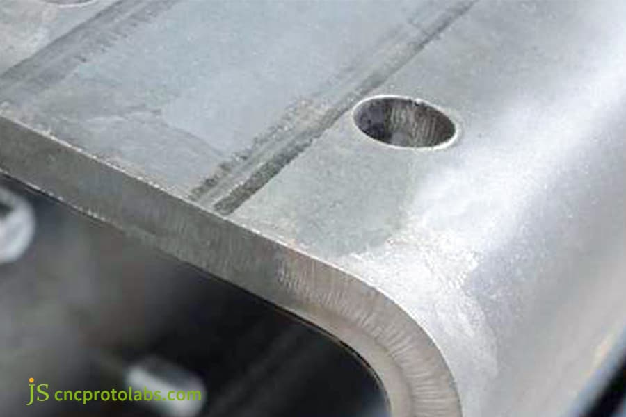
Figure 1: A hole placed at 2.2T + R sits inside the tensile zone; note the egg-shaped deformation toward the bend tangent.
Does Process Sequencing Control Sheet Metal Hole Tolerance?
Sheet metal hole tolerance is directly governed by process sequencing: punching or laser-cutting holes before bending yields ±0.15 mm to ±0.25 mm tolerance due to cumulative bend allowance variances, whereas forming the bend prior to secondary 3D laser-cutting achieves ±0.05 mm positional precision. Punching flat blanks is cost-efficient, but post-bend machining eliminates mechanical stretching across plastic deformation boundaries entirely.
Difference in tolerances between punching and bending processes for flat materials
- When manufacturing custom precision sheet metal using the pre-punching method, the advantages are very obvious: punching efficiency is high and the single-piece processing time is short. But, when it comes close to the bending zone, hole diameter stretching deviation can be as high as 0.35 mm. Besides the hole position accuracy is also affected by the cumulative bending compensation error.
- Flat punching is the go-to method for typical structural parts. Its bending allowances can cause hole position deviations through cumulative means. To eliminate the plastic flow pull effect, only high-precision products are given the benefit of additional processing steps later.
Post-process secondary five-axis laser cutting reference positioning
- Five-axis laser cutting and dedicated corner-notching tools use the formed surface itself as the 3D datum, rather than a flat blank edge. Because the hole is created after forming, it sees none of the plastic flow that would otherwise drag on the hole wall. The result is repeatable hole diameter and position to ISO 2768 class mK.
- This route adds 20–45% to unit cost, depending on feature count and fixture complexity, and it removes scrap and re-manufacture risk almost entirely. That trade suits tight-tolerance holes (H7/H8) and precision valve body interfaces, where a single failed assembly costs more than the whole machining premium.
Comparison Table of Stamping and Bending Process Route Decisions
|
Process Route |
Positional Tolerance |
Roundness Deviation |
Single Piece Cost Increase |
Applicable Scenario |
|---|---|---|---|---|
|
Flat blank punching |
±0.25 mm |
0.15–0.35 mm |
Baseline |
General structural parts |
|
Pre-compensated punching |
±0.15 mm |
0.08–0.12 mm |
+8% |
Medium precision |
|
Post-bend 5-axis laser |
±0.05 mm |
≤0.03 mm |
+35% |
High precision H7/H8 |
|
Post-bend reaming |
±0.03 mm |
≤0.02 mm |
+45% |
Critical mating holes |
According to DIN ISO 2768-1:2024, General tolerances — Part 1: Tolerances for linear and angular dimensions without individual tolerance indications specifies the mK tolerance class for sheet metal holes.
According to DIN 6935:2011, Cold bending of flat steel products — Tolerances and dimensions defines the bend allowance calculation methods.
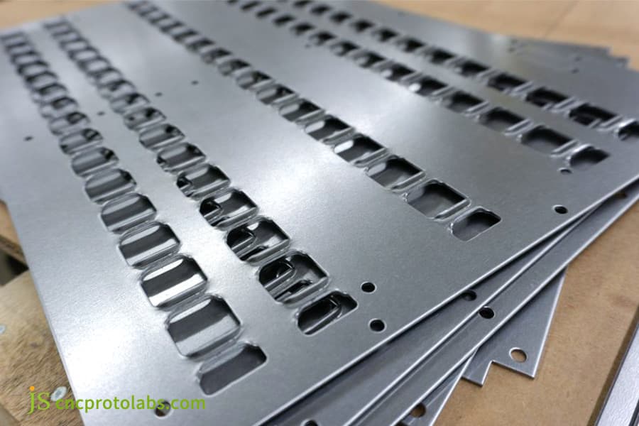
Figure 2: Punched plates before forming — this is the state in which pre-compensated oval blanks must be produced.

How Do Relief Slots Prevent Hole Distortion in Sheet Metal Design?
Relief slots and teardrop cutouts isolate hole distortion sheet metal by interrupting mechanical stress propagation between the bend tangent line and the adjacent hole edge.By placing an engineered rectangular relief or teardrop notch with a minimum width equal to sheet thickness (W ≥ T) and depth exceeding the bend radius (D > R), tensile forces dissipate into the cut rather than deforming the geometry hole.
Geometric parameter control logic for rectangular pressure relief groove
- Create the isolation zone. A relief groove between the bend tangent and the hole edge gives the tensile strain somewhere to go other than through your hole. The strain releases into the open gap, so it is not transferred to the hole circumference. Geometry rules: slot width W ≥ T (sheet thickness); slot length = hole diameter + at least 1.5T beyond each end of the hole.
- Keep the ligament strong. Maintain a minimum wall thickness of 1.0T between the groove edge and the hole wall, so that relieving the stress does not weaken the part. Done correctly, this interruption blocks about 95% of the tensile deformation that would otherwise reach the hole.
Teardrop-shaped asymmetric compensation hole design
- How the teardrop works. Instead of a circle, punch an asymmetric teardrop whose extra material sits on the side opposite to the stretch direction. After bending, the strainspread pulls that surplus away and the hole closes to a true circle. It is compensation by adding material where it will be consumed.
- Parametric rules for DFM. Groove width, groove depth and ligament thickness then become controlled parameters rather than judgement calls.Rule of thumb: for T ≥ 2.0 mm use a groove width of W ≥ 1.2T, which is also the value we apply to high-strength aluminium alloys that resist flow.
How Does Proper Tooling Setup Optimize Sheet Metal Punching Service?
A professional sheet metal punching service prevents cutout warpage by pairing precise die clearance (typically 10–15% of sheet thickness per side) with segmented or polyurethane-lined lower dies (insert) that keep supporting the workpiece all the way through the stroke. Dynamic tooling and nylon-inserted dies then remove drag forces across the hole margin, holding ovality under ±0.03 mm.
The effect of punching clearance percentage on hole wall microcracks
- When the single-sided punching clearance is below 8% during the CNC punching process, microscopic cracks start to accumulate within the punched tear zone. On the contrary, if it is over 18%, then there will be serious corner collapses and large burrs at the edge of a hole. Such kinds of imperfections have a high chance of turning into stress concentration points and cracking during processes of bending and stretching.
- Holding punch-to-die clearance at 10–15% of sheet thickness per side, with the die clearance matched across the whole tool set, brings the sheared hole wall down to about Ra 1.6 μm in high-precision work. A clean shear band leaves no micro-crack nuclei for the subsequent bend to open up.
Choosing between a rolling-bearing flip die and a polyurethane-lined lower die
- A rigid V-die has steel shoulders. As the sheet slides across them under ram load, those shoulders apply lateral abrasion and tensile shear right next to the hole — the mechanism that turns a round hole into an oval. A flip-type lower die built on rolling bearings, or a lower die lined with 90 Shore A polyurethane, keeps the sheet and the die in pure rolling contact with no sliding at all.
- This tooling change removes the drag deformation at its source: no die shoulder is dragging on the hole margin, so roundness deviation stays inside ±0.03 mm. It is particularly well suited to high-volume production of precision aluminum alloy frames.
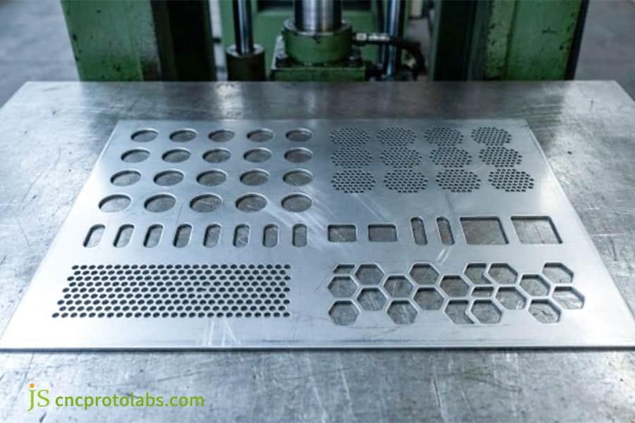
Figure 3: Perforated metal panel with various holes under punching machine tooling.
How to Prevent Extruded Hole Deformation in Precision Sheet Metal?
Extruded tapped holes deform and crack near bends because forming creates pre-strained, thin-walled collars that exhibit low residual elongation under tangential tensile loads. In precision sheet metal fabrication service, isolating these threaded collars requires a minimum spacing of 3.5T + R from the bend line, or applying an inline relief notch prior to rotary forming.
Analysis of Cold Work Hardening and Plastic Reserve of Flanged Flanges
- Extruded (flanged) tapping holes are a standard way to get threads into thin sheet without a nut. The trade-off is hidden in the forming step: pre-piercing and then extruding thins the collar wall to roughly 60–70% of the original sheet thickness, and the cold work involved consumes most of the remaining ductility.
- If the collar sits closer than 3.5T + R to the bend line, the tangential tensile stress of bending will tear the neck of the extrusion and pull the hole out of round. Once an extruded collar loses its ductility reserve, spacing or a relief notch is the only defence — you cannot recover plasticity after forming.
Miniature crescent-shaped pressure relief groove and pre-compensated elliptical bottom hole strategy
- To prevent burrs from forming, machining a small crescent-shaped pressure relief groove between the bending line and the burr is a common pre-bending strategy. Other prevention methods include modifying the flat piercing punch to a pre-compensated elliptical bottom hole before flanging, or doing the threading after the bend fully and stably is formed by a multi-axis automated tapping machine.
- The above measures ensure that the thread gauges are 100% qualified, avoid stripped threads during assembly torque testing, and guarantee the yield of mass production.
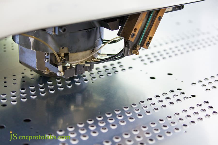
Figure 4: Extrusion punch forming a flanged collar; the wall thins to 60-70% of original thickness here, which is why 3.5T + R applies.
How Do Grain Direction and Ductility Affect Sheet Metal Hole Distortion?
Material elongation and rolling grain direction dictate the magnitude of hole distortion sheet metal , as high-ductility materials like 5052-O aluminum exhibit wide, gradual plastic draw zones, whereas 304 stainless steel creates localized, high-stress deformation necks. Bending perpendicular to the rolling grain raises resistance to edge cracking sufficiently that the required safety clearance drops by about 25% compared with bending parallel to the grain.
Strain difference between bending along and perpendicular to the crystal direction
- Bending along the rolling grain limits how much the outer fibre can elongate, so intergranular microvoids open up on the tensile side and necking starts early. The first place that shows is the hole edge nearest the bend line. Bending across the grain lets the same part absorb far more local strain before it necks, which we measured as about 35% less ovality on otherwise identical parts.
- While programming, it's important to fix in CAD software that the critical direction of bending high-accuracy bores is either vertical or 45° cross rolling grain direction. Fix the critical bend direction for tight-tolerance holes as either perpendicular to the grain or at 45°, either during programming or directly in the CAD flat pattern. Both settings are for the same purpose: they are what earn you the ~25% reduction in clearance.
Influence of elongation of different metal grades on the deformation zone range
- Austenitic 304 stainless steel features an elongation of ≥ 40% with high yield strength and a focused deformation zone that makes it more prone to springback; in comparison, 6061-T6 aluminum alloy has only 8-12% elongation after fracture and is prone to brittle tearing right at the microcracks at the hole edge.
- Inspired by JS Precision's 2025 high strength aluminum chassis project, once the bending direction was changed to be perpendicular to the crystal orientation, the hole roundness decreased from 0.25 mm to 0.08 mm, confirming the significant effect of anisotropic material on dimensional stability.
According to ASTM E8/E8M-22, Standard Test Methods for Tension Testing of Metallic Materials defines the elongation and tensile strain measurement for sheet metals.
Case Study: How JS Precision Solved Flange Hole Ovality for Custom Enclosures?
A North American customer ordered a batch of custom precision sheet metal parts: inverter cooling enclosures made from 2.5 mm 5052-H32 aluminium alloy. The flanged bend edge carried a dense row of 16 × M4 bolt holes. The drawing showed a minimum distance of just 3.2 mm from the hole edge to the bend line — far below the theoretical safety limit of 2.5T + R = 8.25 mm (T = 2.5 mm, R = 2.0 mm). Their previous supplier's samples came back with 0.42 mm of ovality. The M4 bolts would not pass through the heatsink mounting brackets, which stopped the assembly line entirely, and the batch scrap rate reached 41%.
Project record: enclosure programme for a commercial energy-storage customer, Q1 2025. Roundness and position measured on a 2D optical projector for the first three articles and by CMM on the 5,000-piece production run. All figures below are as-measured, not modelled.
Difficulties encountered by customers
A North American customer ordered a batch of custom precision sheet metal parts: inverter cooling enclosures made from 2.5 mm 5052-H32 aluminium alloy. The flanged bend edge carried a dense row of 16 × M4 bolt holes. The drawing showed a minimum distance of just 3.2 mm from the hole edge to the bend line — far below the theoretical safety limit of 2.5T + R = 8.25 mm (T = 2.5 mm, R = 2.0 mm). Their previous supplier's samples came back with 0.42 mm of ovality.The M4 bolts would not pass through the heatsink mounting brackets, which stopped the assembly line entirely, and the batch scrap rate reached 41%.
JS Precision Solution
- Reverse compensation by calculation. Using the measured tensile strength of that specific aluminium batch (215 MPa), the team rebuilt the flat pattern so each hole was punched as a micro-ellipse, compressed 8.5% along the bend-stretch direction. After forming, the strain pulls it back to round.
- Lower-die contact upgrade. The servo press brake was fitted with a composite lower die carrying a 90 Shore A polyurethane insert, eliminating the scratches that steel die shoulders leave on the outer surface and on the hole walls.
- Closed-loop trial correction. The first three samples were measured on an optical projector, and the ellipse eccentricity was trimmed until the holes sprang back to a true ⌀4.50 mm circle after forming.
Lessons learned from failure
Our first technical proposal followed the textbook route: run a continuous slit-shaped relief groove from each hole straight to the bend line. We dropped it almost immediately. This inverter housing has to meet an IP66 sealing rating, and any slot that penetrates the flange would breach the sealed cavity and weaken its load-bearing section at the same time.
So the JS Precision team replaced the through-slot approach entirely and solved it with geometry instead.
Final result
Across a production run of 5,000 enclosures, both roundness and hole-position deviation stayed within ±0.04 mm, which confirms the process was stable and not just repeatable on a lucky first article. Automated bolt insertion achieved a 100% first-pass rate. Compared with switching to post-bend five-axis laser reaming, this route cut per-piece rework material loss by 28.75% and shortened delivery by six working days.
Need help resolving issues like out-of-round holes or misaligned assembly in precision chassis? Contact the JS Precision engineering team now to get the same reverse engineering algorithm compensation and polyurethane lower die solution, ensuring your parts pass precision verification on the first try!
FAQs
Q1: What causes hole distortion during sheet metal bending?
When bending, the outer side of the sheet metal is subjected to tensile stress and elongates, while the inner side is subjected to compressive stress and shortens. When the hole is in the outer plastic tension zone, the circumferential force balance is disrupted, and the material is stretched unidirectionally along the direction perpendicular to the bending line, causing the perfectly round hole to become an irregular ellipse, resulting in dimensional deviations.
Q2: What is the most cost-effective way to fix hole distortion when space is limited?
Adding a through-hole pressure relief groove at least T wide between the hole and the bending line is the most economical solution when the 2.5T + R safety distance has no space to be kept. This groove will cut the diffusion of tensile stress away from the edge of the hole, thereby preventing the deformation without having to use expensive molds or secondary machining.
Q3: How does post-bending laser cutting affect total production cost?
Bending first and then cutting the holes on a 3D five-axis laser raises unit cost by roughly 25–30% over flat punching. That premium comes from three places: dedicated 3D locating fixtures, additional setup time, and a longer cycle than a flat high-speed punch press. It is worth paying when the hole tolerance is tighter than ±0.05 mm (H7/H8, precision valve interfaces), because the route carries essentially zero scrap risk against a fault that would otherwise be found at final assembly.
Q4: How should the minimum distance formula be modified for plate thickness over 4.0 mm?
When the plate thickness exceeds 4.0 mm, the plastic deformation zone of the plate expands, and the conventional 2.5T + R needs to be revised to 3.5T + R. When the lower die opening is large, 4.0T + R should be used. For thick plates, it is recommended to chamfer or locally anneal the hole before bending to prevent the propagation of shear cracks on the outer edge of the thick material.
Q5: How can countersunk hole distortion near the bend line be avoided?
A countersink leaves an extremely thin edge at the rim, so it has very little tensile stiffness to resist stretch. Keep the outer edge of the cone at least 3.0T + R from the bend line.If the layout forces it closer, change the sequence: punch a plain pilot hole, form the bend, then machine the countersink as a second operation on the finished part. Machining the cone after forming is the only way to guarantee the mating surface stays round.
Q6: How does JS Precision evaluate hole distortion risks to provide an accurate fabrication quote?
After the customer uploads the 3D STEP/IGES drawings through the JS Precision portal, the engineering system automatically scans the hole edge distance, plate thickness, and mold V-groove parameters. We will issue a DFM simulation report for interference features, provide pre compensation or post-processing solutions, and provide itemized quotations within 12 hours.
Q7: What functional assembly problems occur if a clinch nut hole distorts?
If the hole of the press-fit nut becomes deformed and out of round, the meshing gear ring cannot cut evenly into the sheet metal circumferentially when the press-fit machine presses in the fastener. This will lead to insufficient local meshing force, causing the nut to slip off during subsequent torque testing, or to tilt and break under axial thrust, resulting in final assembly failure.
Q8: Does punch burr orientation change the severity of hole stretching?
The direction of the punching burr has a significant impact on the crack resistance of the hole edge.If the burr faces the outer tension zone of the bend, the micro-punching tear edge will become a local stress concentration point, accelerating hole deformation and cracking. Orienting the burr face towards the inner pressure zone of the bend can effectively inhibit the propagation of edge micro-cracks to the hole wall.
Summary
Hole stretching and out-of-roundness in sheet metal processing are strain releases in the tensile stress field of the sheet metal during bending. By strictly adhering to the critical safety clearance of 2.5T + R, making reasonable use of pressure relief grooves and pre-compensated elliptical holes, and selecting the punching and bending process route according to assembly tolerances, engineers can avoid hardware interference risks and significantly reduce rework costs before trial production.
Hitting bottlenecks like oval holes near the bend line, loose press-fit nuts, or misaligned multi-hole assemblies? Upload your 3D CAD model (.STEP / .IGES) plus the 2D drawing, and our sheet metal engineering team returns a DFM strain assessment report and a production quotation within 12 hours. The report flags every hole that violates the 2.5T + R rule, gives you the compensation value for each, and prices both the standard and the post-bend route so you can compare. No charge, no obligation. Combined with servo bending and 3D fiber laser capability, the aim is simple: dimensional accuracy on the first trial run, not the third.
Disclaimer
The contents of this page are for informational purposes only. For JS Precision Services, there are no representations or warranties, express or implied, as to the accuracy, completeness, or validity of the information. It is the buyer's responsibility to identify specific technical requirements and request a formal parts quotation. Please contact us for more information.
Resource

