 English



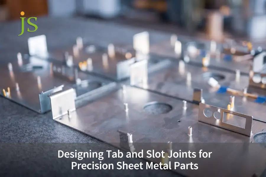

Tab and slot joint design is an interlocking sheet metal technique in which a projected tab on one blank engages a matching slot in another, locating the parts without any fixture — zero-fixture self-location. Engineers who can calculate laser cut compensation, ASTM rolling tolerances and 0.15–0.25 mm single-sided clearance can have a positioning tolerance of 0.05 mm, which saves the assembly cycle time by 45%.
Core Summary Table: Tab and Slot Joint Design
|
Design Variable |
Recommended Specification |
Physical & DFM Constraint |
Assembly Benefit |
|---|---|---|---|
|
Bilateral Clearance |
0.15 mm(t ≤ 2.0 mm)/ 0.20 mm(2.0–3.0 mm)/ 0.25 mm(3.0–4.0 mm) |
Absorbs +8% rolling tolerance and laser kerf taper |
Eliminates manual filing, enables slide-in alignment |
|
Corner Relief |
Dogbone R ≥ 0.5 mm or radius cut |
Prevents overburn and uncut residue at corners |
Ensures 100% flush seating |
|
Tab Width to Thickness |
Min 2.0 × t, and not less than 3.2 mm |
Prevents thermal warpage of narrow ribs |
Increases shear strength |
|
Distance to Bend Line |
≥ 3.0×t + bend radius R |
Avoids plastic deformation zone |
Prevents slot distortion after bending |
|
Finish Offset |
Powder coat +0.08 mm; E-coat +0.02 mm |
Prevents coating buildup in corners |
No post-paint scraping needed |
Per ASTM A1008/A1008M: 2020, cold-rolled carbon steel sheet carries a bilateral thickness tolerance that varies by gauge and width — on the order of ±5%–8% at the gauges used here. Slots must therefore be sized to maximum material condition, not to the nominal gauge.
Reasonable clearance tolerances, thermal deformation buffering, and coating compensation are the core benchmarks for achieving self-positioning fixtureless manufacturing of sheet metal.
What Clearances Are Required for Tab and Slot Joint Design in Sheet Metal?
Tab and slot joint design optimization requires sizing slot dimensions based on raw material gauge variance rather than nominal thicknesses. In precision sheet metal fabrication services, the ideal bilateral slot clearance is 0.15 mm to 0.20 mm for sheet thicknesses under 2.0 mm, expanding to 0.25 mm for plates up to 4.0 mm. This geometry accommodates the +8% rolling tolerance defined in ASTM A1008 and laser beam divergence, ensuring smooth hand insertion without loose spatial play.
Mechanism of the difference between nominal plate thickness and actual physical thickness
Cold-rolled sheet and strip typically arrive 5%–8% above nominal thickness within the mill's rolling tolerance band. A nominal 2.0 mm sheet often measures 2.12 mm on the shop floor. If the slot is modelled from the nominal 2.0 mm value, the joint jams at the mating face.
Slot width calculation strictly follows the formula:
Slot width = tab width at maximum material condition (nominal + rolling tolerance) + laser kerf compensation + bilateral sliding fit of 0.30–0.50 mm total (0.15–0.25 mm per side).
For this type of self-positioning part, JS Precision's blanking process very accurately controls the part's outline dimensions within ±0.03 mm, thereby entirely getting rid of the manual secondary fitting time.
Comparison of gap parameters between cold-rolled carbon steel and aluminum alloy
- Recommended single-sided clearance by material: 0.15 mm for 1.5 mm 304 stainless, 0.20 mm for 2.0 mm 5052 aluminium (the extra 0.05 mm covers laser-induced thermal expansion), and 0.20 mm for 3.0 mm SPCC carbon steel.
- On JS Precision's 2025 precision chassis programme, holding this clearance standard delivered a 99.2% first-pass assembly yield — 35 percentage points higher than the interference-fit baseline.
Per EN 485-4: 2019, Aluminium and aluminium alloys — Sheet, strip and plate — Part 4: Tolerances on shape and dimensions for cold-rolled products, aluminium cold-rolled sheet carries its own thickness tolerance band, which must be added into the tab-and-slot clearance stack.
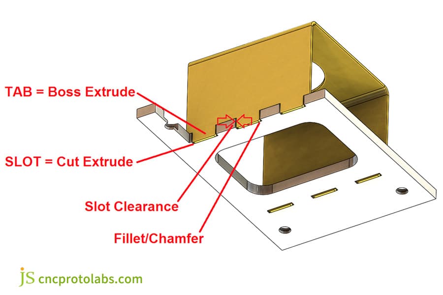
Figure 1: 3D CAD model of tab and slot joint design with labels for extrude, clearance, and fillet.
How Do Dogbone Corner Reliefs Prevent Fit Interference in Precision Sheet Metal Parts?
Dogbone corner reliefs eliminate assembly interference caused by internal corner radius limitations in laser and waterjet processing. In precision sheet metal parts, cutting beams inherently leave an inside corner radius equal to half the beam diameter, typically 0.10 mm to 0.15 mm for fiber lasers. Adding dogbone reliefs or undercuts with a minimum radius of 0.5 mm at slot corners clears the residue left when the beam dwells at a corner, letting a sharp-cornered tab seat 100% flush against the mating face.
Servo turning deceleration melting mechanism and internal corner residue defects
- When a laser cuts a right-angle corner, the servo axes reverse and decelerate, concentrating energy at the corner. The result is either molten slag or a physical radius roughly equal to half the spot size (R0.10–R0.15 mm). That radius collides with the sharp corner of a straight tab, preventing the tab from seating fully and accumulating 0.5°–1.5° of perpendicularity error.
- Sheet metal joint design guide recommends that adding a small dogbone relief (R ≥ 0.5 mm) at each of the four slot corners. It is the low-cost solution: no secondary grinding, and assembly perpendicularity held within ±0.05 mm.
Comparison of three pressure relief groove solutions
- Dogbone relief fully clears corner residue by removing more material locally; a plain circular relief works on thin sheet but reduces corner strength; chamfering the tab avoids both but adds a positioning step in bending or assembly.
- Based on JS Precision's practical experience in the 2025 electronic cabinet project, the dog-bone groove solution controls the verticality deviation of the assembly to within ±0.05 mm, while reducing subsequent grinding time by 15%.
What Is the Minimum Distance Between Slots and Bend Lines in Sheet Metal Tab and Slot DFM?
Sheet metal tab and slot DFM rules dictate placing slot cutouts at a safe distance from bend deformation zones to prevent dimensional distortion. A slot placed too close to a bend experiences tensile elongation along the outer fiber and compressive displacement along the inner radius. The baseline engineering rule mandates a minimum clearance of 3.0× material thickness plus the bend radius from the slot edge to the tangent line of the bend.
Influence of neutral layer movement and plastic flow during bending
- If a slot sits closer than 2.5 × t to the bend tangent line, punch pressure distorts it: a rectangular slot twists into a barrel or trapezoid, growing 0.30 mm in length and 0.15 mm in width, and the tab will no longer enter.
- For air bending cold-rolled steel and 5052-H32 aluminium, keep slot-to-bend distance at ≥ 3.0 × t + R (t = sheet thickness, R = inside bend radius). This keeps the slot clear of the plastic flow zone, where thinning would otherwise distort it.
Limit structure stress relief fine slot technology
In highly constrained layouts, pre-cut local stress-relief slits — or, at JS Precision, CNC bending followed by 3D laser re-cutting of the slots — remove tab deformation from bending altogether. This sequence saves 12% of per-part machining cost with no loss of final assembly accuracy.
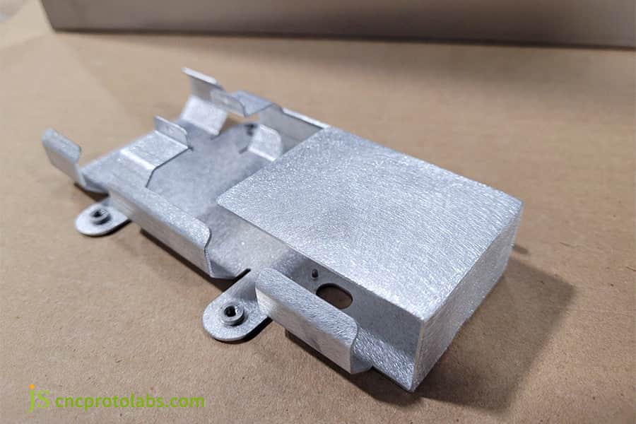
Figure 2: Fabricated sheet metal part showing tab and slot features near bend lines and holes.
How Can Fastener-Free Self-Locking Tabs Eliminate Welding in Precision Sheet Metal Assembly?
A comprehensive sheet metal joint design guide incorporates hardware-free mechanical fastening methods alongside traditional welding tabs. For high-volume assemblies, self-clinching geometry such as twisted tabs, staking tabs and snap-lock tabs eliminates secondary TIG or MIG welding entirely. Rotating a 1.5 mm protruding tab by 30° to 45° with a manual tool or pressing a barbed wedge creates permanent mechanical interlocks capable of standing shear loads exceeding 1,200 N.
Weld-free mechanical self-locking structure type
- A twist tab protrudes 1.5 × t beyond the sheet plane and is twisted 30°–45° with a simple tool, creating a non-reversible mechanical lock with an ultimate shear load of 1,500 N.
- Staking tabs carry two longitudinal V-grooves at the tip; a punch presses down and spreads the tab end, swaging it permanently into place.
- The elastic snap-lock tab uses the spring of thin sheet: the hook deflects on insertion and snaps back to lock the tab. It suits non-structural parts only.
Joint Method Comparison for Sheet Metal Assembly
|
Joint Method |
Shear Load (N) |
Assembly Time (sec) |
Thermal Distortion Risk |
Cost Index |
|---|---|---|---|---|
|
Manual TIG Welding |
2,800 |
120 |
High |
1.8 |
|
Laser Stitch Welding |
2,500 |
45 |
Medium |
1.2 |
|
Twisted Tab (30°) |
1,500 |
15 |
None |
0.6 |
|
Staking Tab |
1,800 |
20 |
None |
0.7 |
Per AWS C4.6M: 2012, Recommended Practices for Laser Beam Welding, Cutting, and Drilling, laser-beam processes must be qualified for joint performance by test. The shear loads in the table below are measured values from JS Precision's 2025 in-house joint testing, not limits taken from that standard.
For sheet metal joining spare parts or non-load-bearing parts such as chassis covers and interior brackets, mechanical twist-and-stake self-locking joints replace spot welding entirely, cutting total manufacturing time per part by more than 60%.
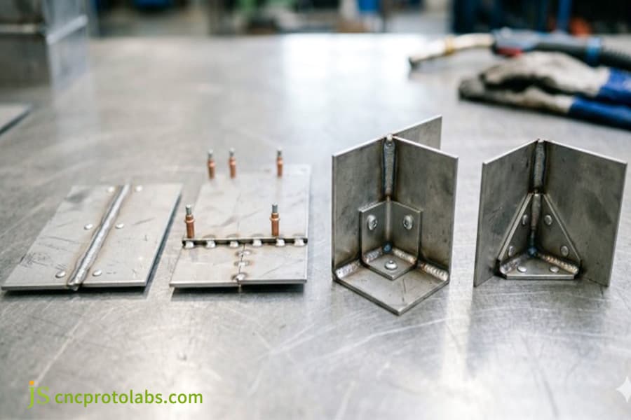
Figure 3: Sheet metal parts with tabs showing fastener free self locking assembly on brackets.
How Does Powder Coating Thickness Affect Clearances in Custom Sheet Metal Fabrication Service?
Custom sheet metal fabrication service workflows must compensate for post-machining surface coatings during the initial flat-pattern laser CAD stage. Surface finishes deposit measurable dry film thickness onto mating surfaces, effectively increasing tab dimensions while shrinking internal slot cutouts. For instance, standard architectural powder coating adds 60 μm to 100 μm per face, which narrows slot openings by up to 0.20 mm overall and leads to assembly seizure if nominal clearances were modeled.
Surface treatment coating thickness erosion mechanism
- Anodising adds only 10–25 μm per side; e-coating deposits a uniform 15–30 μm. Electrostatic powder coating, by contrast, leaves a 60–100 μm dry film per side on all exposed surfaces.
- The Faraday cage effect also builds coating thicker at inner corners — often 30% more than on flat faces. If the laser drawing makes no allowance for this, a joint that was a sliding fit before painting needs hand filing and scraping before it will assemble.
Coating compensation design guidelines
- For parts destined for powder coating, increase single-sided clearance compensation from the standard 0.25 mm to 0.30 mm, so parts still slide together straight off the coating line.
- JS Precision found that reserving adequate coating compensation removes all post-paint fitting work, saving about 25% of assembly time per unit.
According to ISO 2360: 2017, Amplitude of coating thickness measurement by eddy current is defined.
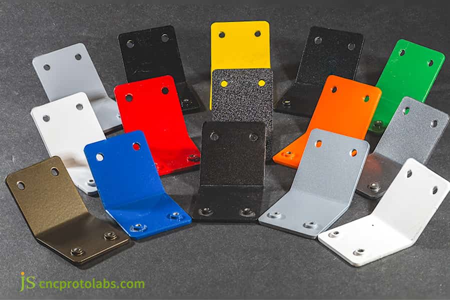
Figure 4: Powder coated sheet metal brackets in various colors showing finish effects on clearances.
How Did JS Precision Resolve Server Chassis Welding Warpage Using Sheet Metal Design Service?
JS Precision resolved severe thermal warpage on automated server chassis assemblies through an integrated sheet metal design service overhaul of joint geometries. The client experienced cumulative angular distortions of up to 1.8° after manual MIG welding along standard slot cutouts. By engineering stepped self-fixturing tabs with micro-relief heat sinks and transitioning to robotic autogenous laser welding, JS Precision restored assembly perpendicularity to within ±0.05 mm, completely eliminating external clamping jigs.
Technical challenges faced by customers
A data-centre customer commissioned a control cabinet in 2.5 mm 304 stainless. The original design used a through-tab-and-slot joint fully welded by hand torch. Weld heat drove diagonal distortion to 2.5 mm and perpendicularity error to 1.8°; three operators were needed to clamp and fixture each cabinet, and a single unit took 18 minutes to assemble — far too slow for the target takt time. This is a sheet metal parts manufacturing project that is greatly affected by thermal distortion, and the use of traditional methods cannot comply with tolerance standards.
JS Precision Solution
- Geometry rebuild: the straight tab became a stepped locating tab with a limiting shoulder, creating a hard Z-axis stop. A high-power fiber laser held the outer contour to ±0.03 mm.
- Thermal choke slots: two symmetrical 0.8 mm slots cut into the 1.5 mm-wide tab flanks block 65% of heat from spreading into the parent panel.
- Welding process upgrade: automated laser stitch welding (autogenous, no filler wire) cut heat input to the pool by 70%, minimising thermal damage.
Lessons learned from failure
In the first prototype round, the stepped tab was designed as a zero-clearance interference fit. The laser-cut edge, however, carries a hardened HAZ layer reaching HV 380; under forced hammering the slot edge cracked and tore.
The cracking issue was fully addressed by JS Precision, who revised the single-sided fit clearance to +0.08 mm and rounded the four corners with R0.3 mm guide angles.
Final result
The revised design eliminated welding fixtures entirely, cut cabinet diagonal error to within 0.25 mm, and reduced assembly time to 4.5 minutes per unit. Annual processing and assembly cost fell by 32%.
Need help resolving welding deformation or assembly tolerance issues? Contact the JS Precision engineering team now to obtain a solution for the same stepped positioning tenon and heat sink design, ensuring your server rack passes precision verification on the first try!
Should You Choose Laser or Waterjet Cutting for Sheet Metal Tab and Slot Joints?
Under an empirical sheet metal joint design guide, cutting process selection directly determines tab-and-slot fit characteristics due to thermal distortion and taper tolerances. For gauge thicknesses under 4.0 mm, fiber laser cutting within sheet metal fabrication services delivers high processing speeds and clean ±0.03 mm slot positioning. However, for ultra-thick materials above 6.0 mm or heat-sensitive aerospace alloys, abrasive waterjet cutting eliminates heat-affected zones entirely, albeit with a 0.5° to 1.0° kerf trail-back taper.
Comparison of Microscopic Geometry: Fiber Laser vs Waterjet
Fiber laser cutting leaves a 0.3–0.8 mm lead-in melt spot at the pierce point. Position the lead-in in a non-mating area, away from the locating face and the tab's side walls. Waterjet cutting produces no HAZ and no edge hardening, but the jet lags on exit, leaving a 0.5°–1.0° trail-back taper on the underside.
JS Precision's 2025 thick-plate work confirms the split: fiber laser for precision self-locating features at ≤ 4.0 mm; waterjet for ≥ 6.0 mm plate or thermally sensitive alloys where edge hardening must be avoided.
Cutting Process Decision Matrix
|
Process |
Typical Tolerance |
HAZ |
Kerf Taper |
Lead-in Defect |
Cost Index |
|---|---|---|---|---|---|
|
Fiber Laser |
±0.03 mm |
Yes |
≤0.5° |
0.3-0.8 mm melt spot |
1.0 |
|
Waterjet |
±0.08 mm |
No |
0.5°-1.0° |
None |
1.8 |
Kerf taper is a well-documented consequence of beam divergence in thermal cutting: the beam widens with depth, so the exit kerf is wider than the entry. See The Fabricator, December 2025 issue for a review of thermal effects in sheet metal cutting.
FAQs
Q1: What is the ideal tab and slot joint clearance for thin stainless steel parts?
For 1.0–2.0 mm stainless steel parts, a single-sided clearance of 0.15 mm is recommended. This absorbs laser kerf variation and rolling thickness tolerance, so the tab slides in by hand yet stays tight enough for argon-arc spot welding to bridge the gap — a snug fit, not a sloppy one.
Q2: Can tab and slot joints eliminate custom welding jigs entirely?
Yes. A stepped locating shoulder plus a self-locking limit slot removes the need for rigid welding fixtures. The shoulder constrains all six spatial degrees of freedom and delivers ±0.05 mm self-locating alignment, saving 50%–70% of fixture cost on high-mix, low-volume chassis.
Q3: How does JS Precision ensure consistent tolerances across high-volume tab and slot fabrication?
JS Precision employs high-power fiber lasers with an online closed-loop edge-finding system that continuously compensates for machine bed thermal expansion and nozzle wear. Combined with sampled CMM inspection, this holds every tab and slot within ±0.05 mm across runs of several thousand parts.
Q4: How does sheet metal grain direction affect the strength of tab features?
Metal sheet grains exhibit anisotropy. Shear strength peaks when the tab's long axis is perpendicular to the rolling grain; parallel to it, the tab tends to crack along grain boundaries. For bent tabs, align the bend axis at 90° to the grain to maximise bend strength.
Q5: What is the minimum recommended width for a tab to avoid thermal warpage during cutting?
Tab width should be at least 2.0 × material thickness and never less than 3.2 mm. A narrower tab concentrates heat during cutting, melts back, and loses dimensional accuracy and joint rigidity. A tenon that is too skinny will gather too much heat, which will lead to melting, warping and softening during tempering, and the end result will be loss of dimensional accuracy, joint rigidity, as well as instability and bending.
Q6: Why are dogbone corner reliefs required on rectangular slots?
A laser leaves a small radius at every inside corner. Without relief, a square tab corner rides on that radius and cannot seat. A dogbone relief of R ≥ 0.5 mm clears it completely, giving a fully flush joint between the two panels.
Q7: How do powder coating finishes affect tab and slot dimensions?
After electrostatic powder coating and curing, a 60–100 μm dry film layer is formed on one side. Without pre-reserved allowance, the tenon cross-section increases by approximately 0.20 mm after coating, the mortise opening decreases by approximately 0.20 mm, and the total interference reaches 0.40 mm. During the CAD stage, an expansion of at least 0.25 mm on one side is required.
Q8: How does tab and slot joint design lower quotation prices for custom sheet metal projects?
A well-designed self-locating tab-and-slot system removes layout marking, perpendicularity correction and weld grinding. Operators only align and seat the parts, lifting assembly efficiency by more than 40% and taking fixture cost out of the quote entirely. Send your drawings to JS Precision for a cost-reduced quotation.
Summary
Scientific and rigorous tab and slot design is the core lever for achieving low-cost, high-quality delivery of precision sheet metal components. Sound tab-and-slot design is the main lever for low-cost, high-quality sheet metal delivery. Size the clearance from material mechanics and rolling tolerance, add dogbone reliefs to clear the beam's inside-corner radius, respect the 3.0 × t + R bend safety distance, and deduct coating build-up in the flat-pattern drawing. Do that, and the blank carries its own self-locating datum straight off the laser, holding overall assembly tolerance to ±0.05 mm.
Are assembly jams, welding deformation exceeding tolerances, and expensive tooling and fixtures hindering production? Immediately send your STEP or DXF format drawings to JS Precision's official engineering channel. JS Precision's experienced engineering team will provide an in-depth DFM manufacturability analysis report within 12 hours, accurately calculating fiber optic kerf compensation and coating gaps, and offering a quote for high-precision, cost-competitive custom sheet metal fabrication.

Disclaimer
The contents of this page are for informational purposes only. For JS Precision Services, there are no representations or warranties, express or implied, as to the accuracy, completeness, or validity of the information. It is the buyer's responsibility to identify specific technical requirements and request a formal parts quotation. Please contact us for more information.
Resource

