 English



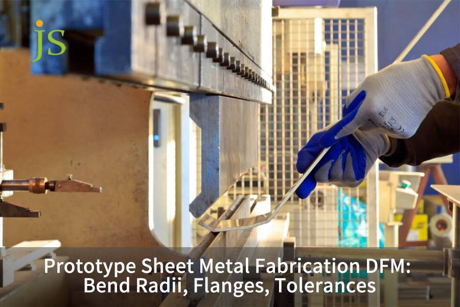

Prototype sheet metal fabrication requires designing for manufacturability (DFM) by standardizing bend radii to 1.0t, cumulative tolerances ranging from ±0.20 mm (single bend) up to ±0.50 mm for 3 bends and ±0.60–0.80 mm for 4 or more bends. By adhering to DFM geometric constraints at the drawing stage, one can prevent the four most common defects — outer-fillet cracking, flange slippage, hole distortion, and assembly misalignment.
Prototype Sheet Metal Fabrication DFM Guidelines & Engineering Limits
|
DFM Design Dimension |
Recommended Engineering Baseline |
Shop Floor Limit |
Common Failure Mode |
Optimization Solution |
|---|---|---|---|---|
|
Bend Radius |
R = 1.0t (AL 5052/SPCC) |
R = 0.5t (special die required) |
Outer radius micro-cracks, thinning |
Bend perpendicular to grain; brittle alloys R >= 1.5t |
|
Min. Flange Height |
L_min = 4t + R (for V = 8t); 3t + R (for V = 6t) |
L_min = 3t + R (narrow V-die) |
Flange slips into V-groove, angle deviation |
Increase hem length or add relief notches |
|
Hole-to-Bend Distance |
>= 2.5t + R |
>= 1.5t + R (secondary drilling) |
Hole elongation, PEM nut loosening |
Add stress-relief slots outside deformation zone |
|
Single Bend Linear Tol. |
±0.20 mm |
±0.10 mm (electro-hydraulic sync) |
Thickness variation, springback drift |
Unify single datum surface positioning |
|
Multi-Bend Stacking Tol. |
±0.50 mm (3 bends); ±0.60–0.80 mm (>=4 bends) |
±0.25 mm (process compensation) |
Flat pattern error, anisotropy stacking |
Use slotted holes and floating fasteners |
Sources: International Organization for Standardization (ISO) — ISO 2768-1:1989, General Tolerances, Part 1: Tolerances for Linear and Angular Dimensions without Individual Tolerance Indications; American Society of Mechanical Engineers (ASME) — ASME Y14.5-2018, Dimensioning and Tolerancing.
Key Takeaways
- The inner bend radius is typically set to 1.0t (one material thickness). 6061-T6 hard aluminum requires R >= 2.0t (up to 3.0t), and cold-worked stainless steel requires R >= 1.5t. Bend lines should run perpendicular to the rolling grain to prevent cracking.
- The standard V-die opening (V = 6t–8t) limits the minimum flange length; for the common V = 8t die, the minimum flange is 4t + R; for V = 6t, it reduces to approximately 3t + R. A shorter flange slips into the V-groove during forming, causing angle deviation.
- Multiple bending operations should be accompanied by a tolerance-absorbing structure. Avoid specifying ±0.05 mm end-to-end tolerances across multiple bends.
Why Is Selecting the Correct Sheet Metal Bend Radius Critical for Prototype Sheet Metal Fabrication?
The bend radius marks the material's strain limit. Choosing it arbitrarily leads to edge cracks, frequent tool changes, and flat-pattern errors. A proper sheet metal bend radius is fundamental to ensuring mechanical strength and dimensional accuracy of prototype parts.
Recommended minimum bending radius for common materials
Across JS Precision's communication chassis projects, the plastic-deformation limits of different materials vary significantly — an arbitrary radius can cause cracking and scrapping directly.The table below summarizes the key forming parameters for four commonly used sheet metal materials:
|
Material Grade |
Tensile Strength (MPa) |
Elongation (%) |
Recommended Min. R/t |
Springback Angle (°) |
|---|---|---|---|---|
|
AL 5052-H32 |
210-260 |
12-18 |
0.5-1.0 |
1-2 |
|
AL 6061-T6 |
290-310 |
8-10 |
2.0-3.0 |
3-5 |
|
SUS304 |
520-720 |
40-50 |
1.5-2.0 |
2-5 |
|
SPCC |
270-330 |
30-40 |
1.0 |
1-2 |
Sources: ASTM International — ASTM B209 (current edition), Standard Specification for Aluminum and Aluminum-Alloy Sheet and Plate; ASTM A240/A240M (current edition), Standard Specification for Chromium and Chromium-Nickel Stainless Steel Plate, Sheet, and Strip for Pressure Vessels and General Applications.
The impact of uniform bending radius on production efficiency
Maintaining a fixed bend radius in all the drawings helps prevent the machine operator from getting involved in frequent changes of punches and dies. We fully conform to this tolerance in our in-house designs, achieving a multi-bend chassis assembly pass rate of nearly 98%. For the prototype sheet metal fabrication, this leads to shorter delivery cycles and less cost per unit.
Linear dimensional tolerance of class m is recommended with tolerance of ±0.30 mm on a length of 30 mm to 120 mm by cold bending of sheet metal as per ISO 2768-1:1989.
We fully conform to this tolerance in its inhouse designs thereby raising the pass rate of multi-bend chassis assemblies close to 98%.
Want to check whether your material choice suits rapid prototyping? Reach out to our engineers. We will generate a complimentary materials formability test report for you.
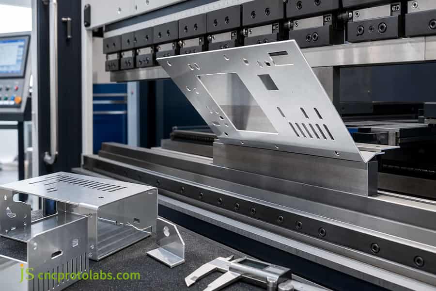
Figure 1: Press brake bending prototype sheet metal part with brackets.
How to Optimize Sheet Metal Flange Design and Bend Reliefs in Custom Sheet Metal Fabrication Service?
Flange design must satisfy the geometric support limit of the air bending V-die opening; bend reliefs eliminate triaxial tensile stress concentration at corners. Proper sheet metal flange design and relief geometry prevent flange slipping and sidewall tearing.
Relationship Between Flange Length and V-Die Opening
A standard air-bending V-die opening is V = 6t–8t. The supported flange distance directly determines forming stability.
- Minimum flange formula: When the flange length is shorter than 4t + R, the sheet metal edge cannot be placed on the shoulder of the lower die and it will slide into the V groove during forming process, resulting in angle deviation.
- Solution with narrow slot dies: where there is lack of space availability, When space is constrained, a narrow V-die (V = 4t–5t) reduces the minimum flange to 3t + R, but tooling setup costs increase.
- Process-flanging technique: Reserve an extended process flange on the CAD flat pattern, then laser-cut the excess off after bending. After forming and bending, the excess edge is removed by doing secondary laser cutting.
Standard Bend Relief Design Rules
For adjacent flanges that must be parallel or vertically bent, a bend relief is the key to preventing tearing. The relief's geometry must match the flange height to prevent over 90% of corner cracks.
- Width: Bend relief width ≥ 1.0t (and ≥ 1.5 mm) to accommodate laser cutting.
- Depth: ≥ R + t, to fully interrupt the triaxial tensile-stress path.
- Shape comparison: Rectangular reliefs cut fast but may develop micro-cracks at sharp corners; teardrop reliefs resist tearing better but take 15–20% longer to cut.
Struggling with bend relief sizing or flange height? Send your 2D drawings to us, and the JS Precision team will review your flange and relief design and give suggestions for changes so that your design will at least meet the 4t+R lower limit.
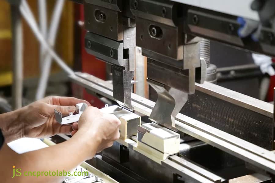
Figure 2: Worker optimizing sheet metal flange design on press brake.
How to Prevent Hole Distortion and Feature Deformation in Sheet Metal Design Service?
Placing holes or slots within the plastic deformation zone of a bend causes wall distortion, elongation, and positional shift. Maintaining adequate distance between hole edges and the bend tangent line is essential for fastener assembly precision sheet metal design service .
Safe Hole-to-Bend Distance Formula
JS Precision applies a safety factor and recommends placing holes at ≥ 2.5t + R from the bend tangent to fully clear the deformation zone.
- Standard round holes: keep the hole edge at least 2.5t + R from the bend tangent to keep it outside the deformation zone.
- Countersunk and oversized square holes: keep spacing ≥ 3.0t + R, since the conical geometry of countersinks makes them prone to distortion.
- Failure scenario: if the holes are too close press-fit nuts can loosen and interfere with mating bolts — in severe cases the entire part must be scrapped.
Alternatives for holes that are too close together
In some cases, if the structure needs to have the hole very closely located to the bend line at the sheet metal, these two alternate solutions can be applied to manage the near sheet metal bend radius features effectively.
- Stress-relief slit: Cut a narrow slit parallel to the bend line, just outside the deformation zone, to relieve tensile stress.
- Two-stage CNC milling: First form the bend, then mill holes on the formed surface. This reaches ±0.05 mm precision but raises per-piece cost by roughly 8–15%.
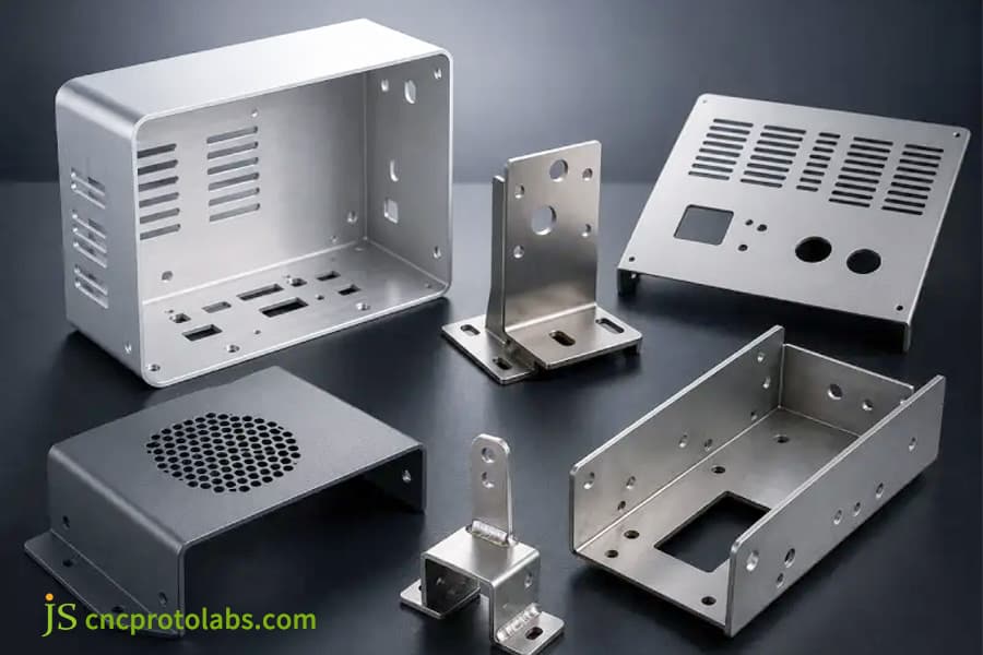
Figure 3: Various precision sheet metal enclosures and brackets collection.
How to Control Sheet Metal Tolerance and Stack-Up Errors in Complex Prototype Sheet Metal Parts?
Sheet metal tolerance results from the combination of laser cutting flatness (±0.10 mm) and bending angular accuracy (±0.5° to ±1.0°). Multi-bend operations amplify these errors linearly.
Why Laser-Cutting and Bending Precision Differ
Fiber-laser blanking and press-brake bending derive their precision from different sources, so each must be controlled separately to hold final dimensions of prototype sheet metal parts.
- Laser cutting accuracy: The flat contour accuracy can be as high as ±0.10 mm, but because of the release of residual stress in the metal sheet, residual stress release can warp the edges of large parts by 0.05–0.15 mm.
- Bending: Linear tolerance per bend is ±0.20 mm and angular tolerance is ±0.5°–1.0°, varying with sheet-thickness tolerance (±5–10%) and springback.
- The cumulative effect: in case of chassis type structures with four or more consecutive bends the overall span deviation will usually be ±0.60 mm to ±0.80 mm.
Comparison of tolerances between ISO 2768-m and ISO 2768-f
Blindly applying ±0.05 mm machining tolerances to sheet metal drawings drives rejection rates up sharply. Below is a table that shows the right levels of tolerance that should be employed for prototype sheet metal fabrication.
|
Dimension Range (mm) |
ISO 2768-m (Medium — recommended for sheet metal forming) |
ISO 2768-f (Fine — typically achievable only by machining) |
|---|---|---|
|
0.5 – 3 |
±0.10 mm |
±0.05 mm |
|
3 – 6 |
±0.10 mm |
±0.05 mm |
|
6 – 30 |
±0.20 mm |
±0.10 mm |
|
30 – 120 |
±0.30 mm |
±0.15 mm |
|
120 – 400 |
±0.50 mm |
±0.20 mm |
Sources: International Organization for Standardization (ISO) — ISO 2768-1:1989, General Tolerances, Part 1: Tolerances for Linear and Angular Dimensions; Deutsches Institut für Normung (DIN) — DIN ISO 2768-1:1991-06, Allgemeintoleranzen.
Engineering Solutions
To absorb the cumulative out-of-tolerance caused by multiple bends, JS Precision uses three proven methods:
- Slotted holes: Design mating surfaces with slotted holes to absorb ±0.35 mm along the bend-stacking direction.
- Dimples: Stamped self-locating dimples align parts during assembly; their self-positioning action removes assembly deviation.
- Floating nuts: A floating press-fit nut gives the bolt ±0.3 mm of positional freedom.
Confused about the accumulated tolerances arising with multiple bends? Book a free 15-minute call with an engineer to review your drawing's tolerance callouts.
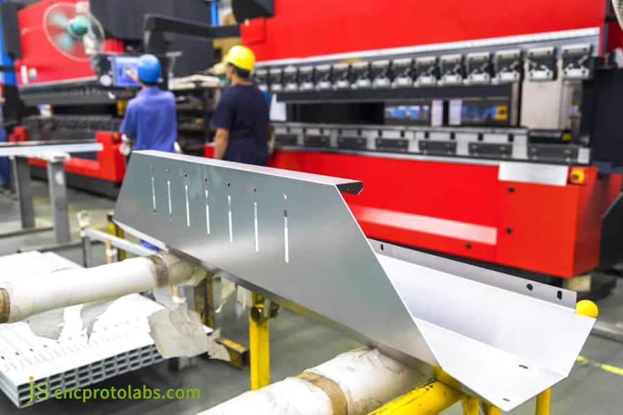
Figure 4: Complex prototype sheet metal part on factory floor for review.
What Are the Formability Differences Among Common Alloys in Sheet Metal Fabrication Service?
Yield strength, elongation, and work-hardening index determine the minimum bend radius and springback angle of each alloy. Adjusting compensation based on material grade and heat treatment before prototyping is critical to eliminate fractures and out-of-tolerance conditions in any sheet metal fabrication service .
Aluminum Alloy: Forming Comparison of 5052-H32 and 6061-T6
The most frequently used material for prototyping is aluminum alloy. Since different grades' formability varies greatly, it impacts the choice of sheet metal bend radius.
- 5052-H32: 12–18% elongation, highly formable, permits R = 0.5t–1.0t — the best choice for prototypes.
- 6061-T6: Elongation is rather low at 8%-10%. Its high yield strength (290–310 MPa) means small-radius bending cracks it along grain boundaries. Use R ≥ 2.0t, or anneal to the O temper before bending.
- Lessons learned by JS Precision: In an early weight reduction plan, we bent 6061-T6 directly and the part cracked. After presenting the customer with comparison of elongation data, we switched to 5052-H32, which met the strength requirement and eliminated forming cracks.
Forming characteristics of stainless steel and carbon steel
Stainless steel and carbon steel are two other frequently used materials, each with distinct work-hardening and springback characteristics.
- SUS304/SUS316: the overbend compensation must equal the measured springback angle, typically 2°–5°; for SUS304 with a springback of 5°, the programmed angle would be 95° to achieve a 90° final bend. SUS316 exhibits similar forming characteristics to SUS304 and is not separately tabulated above.
- SPCC: Low yield ratio and consistent springback (1°–2°), suited to complex bending and deep drawing. A standard R = 1.0t ensures good forming quality.
- Copper C1100 and brass H62: Strong grain anisotropy — crack resistance is better across the grain than along it, so rolling direction must be considered when orienting bends. Copper C1100 and brass H62 are specialty materials not included in the standard table above; contact JS Precision for material-specific DFM data.
Per ASTM E290-22, the minimum bend radius is the smallest radius at which no visible cracks appear on the outer surface of the specimen during the bend test.
We follow this test procedure as part of workshop calibration and maintain a minimum-bend-radius database for every incoming sheet material to guarantee first-article pass rate of prototype sheet metal fabrication.
How to Accurately Compensate for Springback and K-Factor in Sheet Metal Design Service?
Springback compensation and K-factor parameters determine the dimensional match between the 3D CAD flat pattern and the formed part. Calibrating the bend deduction in design software eliminates flat pattern errors before laser cutting begins in sheet metal design service.
The mechanical principle of springback compensation
Springback is the elastic recovery that occurs when a formed part is unloaded from the die. It directly affects dimensional accuracy.
- Springback angle: It scales mainly with yield strength and is inversely proportional to the elastic modulus E.
- Compensation: Add the springback angle to the target bend during programming. For a 90° finished angle in SUS304, program 93°.
Workshop Measurement Methods for K-Factor Calibration
SolidWorks, Creo, and other CAD software normally use fixed K-factors (0.44 or 0.50), but these cause substantial flat-pattern errors that vary with sheet thickness and tooling — so K must be calibrated by physical measurement.
- Error caused by default parameters: For 1.5 mm SUS304 sheet metal, using the default K factor of 0.44 may result in a deviation of 0.3-0.5 mm in the length of the folded part. This deviation accumulates linearly: for example, with 5–6 bends at 0.3–0.5 mm per bend, the total reaches 1.5–3.0 mm for multiple bending components.
- Steps to calibrate: perform 90° air bending on the same set of materials, measure the Bend Deduction (BD), back-calculate the true K-factor, and enter it into the CAD/CAM unfolding system.
- Results and verification after testing: JS Precision carried out testing as well as calibration. After testing and calibration, the first-article forming pass rate exceeded 98%, eliminating at least two trial-bend iterations.
JS Precision Case Study: DFM Optimization of Multi-Bend Telecom Enclosure Prototypes
The engineering team of JS Precision solved the issue of interference and hole position deviation during the prototyping for a North American communications client by completely reworking the bending process, adding bend reliefs, and adjusting baseline tolerances.
Customer's problem
A 5G outdoor communication housing made of 1.5 mm AL 5052-H32 sheet, composed of 12 continuous forward and reverse bends.
- Original design deficiencies: The inner bend radius was 0.5 mm (i.e. less than the 1.5 mm sheet thickness), and no bend relief was provided at adjacent flanges.
- Failure of the first prototype: upon testing with the initial unit, microcracks appeared at the folding corner of the bend, and the farthest mounting hole's coaxiality error reached 0.65 mm — far exceeding the drawing spec.
JS Precision Solution
Through DFM optimization, the engineering team improved four design dimensions.
- Unified bend radius: All bend radii were set to 1.5 mm (R = 1.0t) to eliminate outer-edge tearing.
- Added bend relief: A 1.8 mm × 3.0 mm rectangular relief was added at the flange intersection to relieve corner stress.
- Re-sequenced bending: The CNC bend order was rearranged to eliminate tool interference and cut tool changes.
- Tolerance adjustment: The fixed round hole located at the bottom of the chassis converted to slotted holes for ±0.35 mm of compensation, and an electro-hydraulic CNC press brake with dynamic laser angle measurement was used for real-time springback compensation.
Lessons learned from failure
In a separate earlier project, JS Precision's weight reduction attempts involved prototyping 6061-T6 aluminum sheets. Still, the sheets were breaking when being bent directly.
- The underlying reason for the failure was that the elongation of 6061-T6 aluminium is only 8%-10% and R = 0.5t is well below its 2.0t safe minimum.
- Resolution: Supply the customer with elongation data for comparison and replace the material with 5052-H32 aluminum sheet, which met the strength requirement and eliminated forming cracks.
Final result
After these optimizations, the custom sheet metal fabrication service project achieved the following measurable results:
Bending radius correction: changed from a 0.5 mm (R=0.33t) bending radius to a bending radius of 1.5 mm (R=1.0t), which entirely prevents the occurrence of corner cracks.
- Enhanced hole position accuracy: Reduction of the coaxiality deviation of the farthest mounting hole from 0.65 mm to 0.20 mm, a 69% improvement.
- Faster delivery cycle: The sample delivery cycle has been cut down from 10 days to 4 days, a 60% efficiency gain.
- Satisfactory verification results: The overall dimensional tolerance was reduced from ±0.65 mm to ±0.20 mm, approaching but not fully meeting the drawing's ±0.15 mm requirement. The residual 0.05 mm gap was absorbed by the slotted-hole compensation (±0.35 mm allowance), ensuring functional assembly compliance, with no corner cracks; the part passed IP65 sealing and vibration testing.
Sources: JS Precision quality engineering records (QA-2025-TC088).
Want a free DFM manufacturability assessment on your product? Email your 3D CAD model (STEP preferred) to our engineering team — we'll reply with optimization recommendations and a manufacturing quote within 2 hours.
FAQs
Q1: Why is a bend radius equal to material thickness (R = 1.0t) recommended in prototype sheet metal fabrication?
R = 1.0t keeps the outer-layer tensile strain below the fracture limit, preventing outer-fillet cracking and local necking, while matching standard press-brake tooling for shorter setup.
Q2: What happens if a hole is located too close to a sheet metal bend line?
Plastic flow in the bend's deformation zone will stretch a round hole into an ellipse if the edge sits closer than 2.5t + R, causing bolt-assembly issues, fastener stress concentration, and damaged mating surfaces.
Q3: Why is a ±0.05 mm tolerance impractical for multi-bend sheet metal enclosures?
Each bend adds thickness-tolerance and springback variation, and across multiple bends these errors accumulate linearly. Forcing ±0.05 mm produces heavy scrap and sharply raises cost.
Q4: How does JS Precision ensure forming precision on complex prototype sheet metal parts?
JS Precision uses a multi-axis electro-hydraulic CNC press brake with a dynamic laser angle-monitoring system for real-time springback correction. This keeps 4+ bend enclosures consistently within ±0.25 mm.
Q5: What engineering options are available when minimum flange length (4t + R) cannot be met?
One option in the CAD drawing is to have the flange extended on the drawn flat part and then laser-cut after bending and forming, or use a narrow-groove lower die with a polyurethane pad, though tooling setup costs more.
Q6: Can aluminum 6061-T6 sheet parts be bent with tight radii on standard press brakes?
6061-T6 has a fracture elongation of only 8%-10% which is very low and so the tight radii easily crack it along grain boundaries. If bending is unavoidable, use R ≥ 2.0t–3.0t — or start with O-temper annealed sheet, bend, then age.
Q7: What factors determine the quote for prototype sheet metal fabrication?
A quote is based on net material consumption, laser cutting hours, number of CNC bends. A standardized bend radius can cut tool-change cost by over 20%. You can upload your drawings to get a quote.
Q8: What is a sheet metal bend relief and when must it be designed?
Bend reliefs are small slits cut at the root of flanges or at bend intersections. Add them whenever a flange doesn't reach the part edge or two flanges meet perpendicularly, to stop corner cracks from propagating.
Summary
Optimizing prototype sheet metal DFM means setting CAD parameters to match the press brake's physical limits: bend radius R = 1.0t, flange ≥ 4t + R, bend-relief depth ≥ R + t, and pre-reserved slotted holes on mating surfaces. By applying these measures most of the prototyping defects can be prevented right at the drawing stage.
Looking for sheet metal prototype verification with the highest precision? Upload your 3D CAD model and 2D engineering drawings to JS Precision, and our technical team will perform a full DFM analysis and give you optimization recommendations together with a cost estimate within 2 hours.

Disclaimer
The contents of this page are for informational purposes only. For JS Precision Services, there are no representations or warranties, express or implied, as to the accuracy, completeness, or validity of the information. It is the buyer's responsibility to identify specific technical requirements and request a formal parts quotation. Please contact us for more information.
Resource

