 English



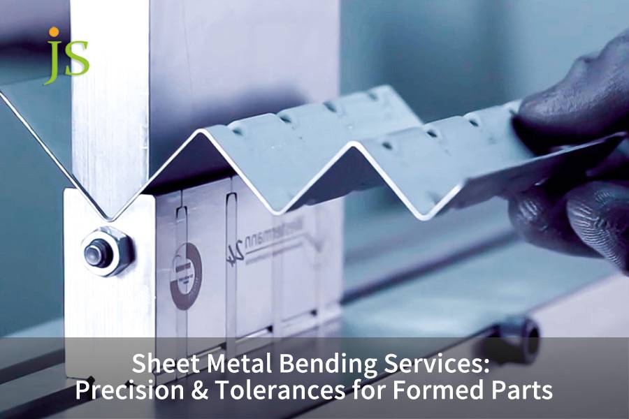

Sheet metal bending services utilize CNC bending machines to process flat metal into structural brackets and shells, achieving standard industrial tolerances of ± 0.020 inches (± 0.50 millimeters) and ± 1.0 °. With CNC press brakes equipped with closed-loop laser angle compensation and dynamic crowning, JS Precision achieves ±0.008" (±0.20 mm) linear accuracy and ±0.2° to ±0.3° angular accuracy.
Sheet Metal Bending Services: Precision & Tolerances Quick Overview
|
Parameters |
Standard Grade |
JS Precision Precision Grade |
Key Control Factor |
|---|---|---|---|
|
Bend Angle Tolerance |
±1.0° |
±0.2° – ±0.3° |
Laser real-time angle measurement + dynamic crowning |
|
Linear Dimension |
±0.020" (±0.50mm) |
±0.008" (±0.20mm) |
6-axis CNC back gauge + datum alignment |
|
Hole-to-Bend Distance |
±0.015" (±0.38mm) |
±0.005" (±0.13mm) |
Relief slot design + pre-deformation algorithm |
|
Process Capability (Cpk) |
Cpk < 1.00 |
Cpk ≥ 1.33 |
Closed-loop angle monitoring + yield strength sampling |
Data source: JS Precision 2025 process capability database; DIN 6935:2011 sheet metal bending tolerances.
Key Takeaways:
Sheet metal bending services use CNC press brakes to form flat sheet into 3D parts. Standard tolerances: ±0.020", ±1.0°; precision systems (laser angle + dynamic crowning): ±0.008", ±0.2°–±0.3°. In practical applications, engineers often use bend angle tolerance calculators to quickly determine the feasible angle range for a given material and thickness.
For Cpk≥1.33 direct assembly, three rules apply: compensate springback with K-factor (0.33–0.45) and rolling direction; set flange height ≥4t and hole-edge ≥2.5t+r; use single absolute datum to eliminate stacking.
What Are the Real Tolerance Limits in Precision Metal Bending Service?
Precision metal bending service gives industrial bending tolerance of ±0.020" linear error and ±1.0° angular offset. Yet, a combination of CNC five-axis positioning with fine micrometric corrections and super-fine precision grind of tooling can push the final limits into ±0.008" (±0.20mm) linear deviation and only ±0.2° to ±0.3° angular variation.
Forming Process Comparison and Stress Mechanism
- Air bending: Highly versatile and best suited to small workloads. Angular tolerance typically ranges from ±0.5° to ±1.0°, making it ideal for multi-type, small-batch production.
- Bottom bending (die bottoming): Tightens tolerance to ±0.2° to ±0.3°, though die changeover costs are higher.
- Coining: Extreme pressure is applied to eliminate springback entirely, achieving accuracy up to ±0.1°. However, it greatly increases die wear and tonnage requirements.
Material and Thickness Tolerance Classification
ISO 2768-m defines different standard and precision tolerance grades by material and thickness. In our medical device housing project, raw material thickness deviations of just a few hundredths of a millimeter changed flat-pattern unfolded dimensions by 0.3–0.8 mm. Furthermore, empirical springback calculations are highly prone to errors from die misalignment.
|
Material |
Thickness (mm) |
Standard Linear (mm) |
Precision Linear (mm) |
Standard Angle |
Precision Angle |
|---|---|---|---|---|---|
|
5052-H32 Al |
0.5–1.5 |
±0.50 |
±0.20 |
±1.0° |
±0.3° |
|
SUS304 SS |
1.0–3.0 |
±0.50 |
±0.20 |
±1.0° |
±0.2° |
|
SPCC CRS |
1.5–6.0 |
±0.50 |
±0.20 |
±1.0° |
±0.3° |
Data source: ISO 2768-m general tolerances.
The ISO 2768-m standard mentions: For linear dimensions, the tolerance range for precision class m will be ±0.2 mm to ±0.5 mm, according to the basic dimension range.
In evaluation of the sheet metal bending tolerances, JS Precision mainly adopts ISO 2768-m as a foundation and simultaneously adjusts the developing factor as the measured yield strength of the material. If the drawing needs very narrow dimensional limits, the engineering personnel of JS Precision will generally propose using techniques under the stress of pressure forming or embossing so that the outcome is uniform. For designs involving the relationship between inner radius and plate thickness, feasibility needs to be confirmed by referring to the sheet metal bend radius tolerance table.
If you would like to have your drawing dimension tolerances crosschecked in terms of whether they can be realized, contact the JS Precision engineering staff for a free DFM tolerance calibration and process recommendation report.
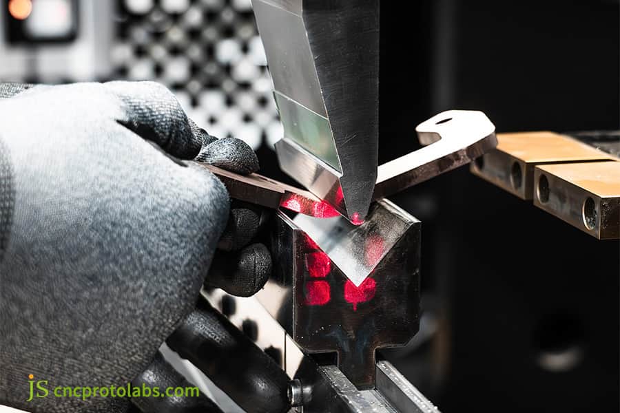
Figure 1: Worker aligning sheet metal for precision bending with laser guide.
How to Control Bend Angle Tolerance and Material Springback Scientifically?
Bend angle tolerance is a material characteristic dependent on tensile strength and bend ratio (radius over thickness). Going from standard 1.0 degree to precision 0.2–0.3 degree bend relies on using over-bend compensation and having a means to dynamically measure the laser angle.
Springback Mechanism and Compensation Formula
- Elastic Recovery Principle: upon completion of metal forming operations, it is the recovery of the crystals' elastically deformed lattice, which results in angular deviation in the workpiece. For 304 stainless steel, the springback angle is 3°–5°, and for 6061-T6 aluminum alloy, the springback angle is 2°–4°.
- Compensation Formula:
Bending Angle = Target Angle + Springback Angle
Springback angle Δα ≈ (3σ_y × R) / (E × t), with σ_y being the yield strength, E is the elastic modulus, R is the inner radius, and t stands for the thickness of the plate material.
- Lower die opening selection: Suggested V = 6t–8t. Overly small openings cause the springback to worsen while overly large openings may create a loss of the shape at the corners.
Rolling Direction and Batch Consistency:
- Bending along the grain: susceptible to cracking and experiences major variations in springback (above ±0.5°).
- Perpendicular or at 45 degree to the grain: leads to an even distribution of strain while keeping springback fluctuations to within ±0.25°.
- JS Precision dynamic compensation: uses a CNC bending machine fitted with hydraulic dynamic deflection compensation (Crowning) and laser angle measurement to continuously and automatically correct springback deviations of each part resulting in stable angle tolerances within ±0.2° for custom sheet metal bending mass production.
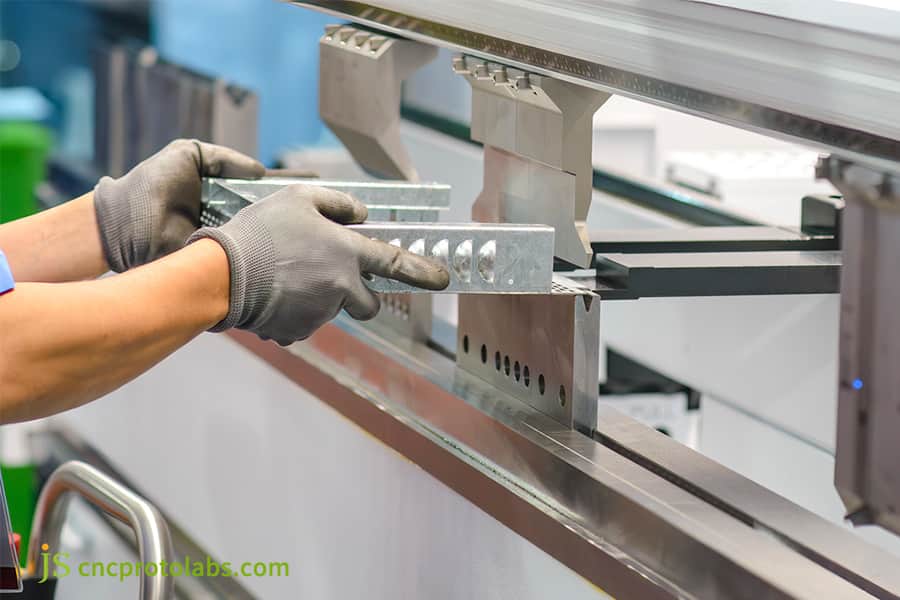
Figure 2: Worker controlling bend angle tolerance on press brake machine.
How to Optimize DFM Rules to Prevent Hole Distortion in Custom Sheet Metal Bending?
Minimum hole-edge distance in custom sheet metal bending needs to be at least d≥2.5t + r and minimum flange height to be b_min≥4t + r to stop interference from occurring. Laser cutting of relief areas or pre-bending would need to be performed in situations where the clearance distances are not sufficient.
Stress in the Deformation Zone and Deformation Prevention Schemes
- Hole Tension and Edge Concavity: when the hole edge distance is less than two times thickness, tensile stress concentration causes deformation of the hole.
- Three countermeasures:
- Use of pressuring relief hole in pre-punching process (diameter ≥ 1.5t).
- Carry out bending operation before laser cutting with secondary operation (high-precision holes).
- Use a customized clearance mold to increase local clearance space.
JS Precision Automated DFM Check
JS Precision performs an automatic DFM risk check during the quote phase. This step allows the identification of defects like minimal hole edge gap, and very small flanges. Modification suggestions are made and returned to the client within a 24-hour period. Through DFM checks for metal bending for formed parts, the manufacturer can avoid 80% of the prototyping issues.
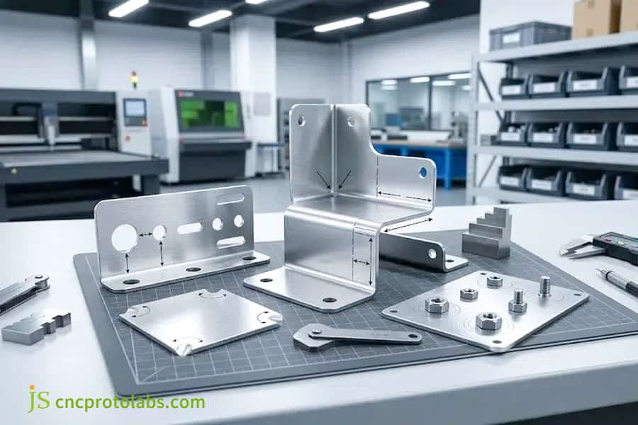
Figure 3: Various custom sheet metal bending parts optimized with DFM rules.
How to Eliminate Tolerance Stacking in Sheet Metal Bending Services for Complex Enclosures?
Sheet metal bending services suffer from cumulative tolerance driven by back-gauge datum drift and bend deduction error. With a unified measurement datum and optimized bend sequence, cumulative tolerance error (CTE) drops from the traditional ±1.5 mm range to ±0.008" (±0.20 mm).
Dimension Chain Transfer and Positioning Methods
- Chain Positioning: each bend is positioned referring to the preceding bend so that the deviations keep compounding with every next bend leading to an overall accumulated deviation exceeding ±1.5 mm.
- Absolute Coordinate Positioning: One reference edge and positioning pin hole are used for the entire workpiece and the cumulative error caused by the chain method is entirely avoided while dimensional deviation remains well within ±0.20 mm.
- 6-Axis Backgauge Configuration: through a 6-axis backgauge independently controlling (X1/X2, R1/R2, Z1/Z2) axes as well as a 3D process interference simulation the positioning accuracy of each bend remains highly stable.
JS Precision Reference Optimization Scheme
Based on our real-life project of designing an analyzer chassis, the initial drawings made use of chain-style annotations which caused a 1.2mm deviation of the alignment holes after 7 bends. The JS Precision engineering team made the base plate positioning pin holes the primary reference and altered the bending sequence so that parts expand from the center outward, formed part precision improved to within ±0.15 mm and the Cpk got to 1.41.
Do your multi-bend assemblies have a problem with alignment? Try out our free cost estimation. JS Precision will offer you a dimensional chain analysis and process improvement advice.
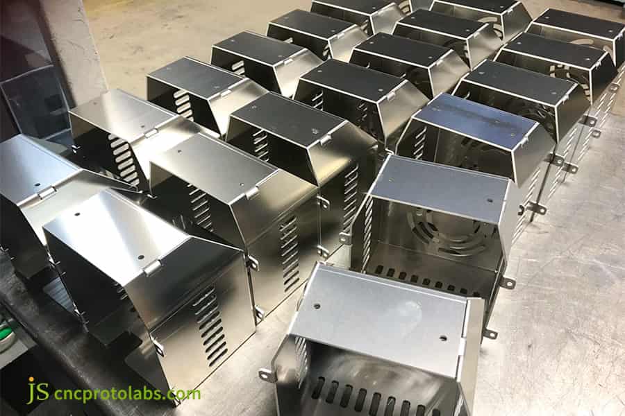
Figure 4: Batch of complex metal enclosures produced by sheet metal bending services.
Custom Sheet Metal Bending vs Secondary CNC Machining: Which Offers Better ROI?
Custom sheet metal bending can be customized for parts needed with precision-grade tolerances of ±0.20 mm (±0.008") and it can reduce production costs by 45–60% and cut lead times by up to 70% compared with rough bending followed by secondary CNC milling.
Process-Tolerance-Cost Decision Matrix
|
Decision Scenario |
Recommended Process |
Cost per Part (USD) |
Lead Time (days) |
|---|---|---|---|
|
Tolerance≤±0.05mm |
Full CNC machining |
$12–$25 |
5–8 |
|
Tolerance ±0.05mm – ±0.20mm |
Laser cut + precision bend + ream |
$6–$10 |
3–5 |
|
Tolerance≥±0.20mm |
Precision bending only |
$3–$6 |
1–3 |
Data source: JS Precision 2025 cost analysis for 1.5mm SUS304 chassis (volume 2,000 pcs).
Economic Scope of Hybrid Process Techniques
- Instrument Housing: the unit cost is dropped by precision bending which eliminates the need to hollow out solid aluminum blocks via CNC machining, from $18 to $7. Cycle time has also been reduced from 6 days to 2 days.
- Load-bearing Pallet: it is possible to manufacture a piece by direct bending without having to weld and mill, saving 50% on cost, when the product tolerance is ±0.25 mm.
- Medium Precision Solution: A combination of laser cutting and precision bending of keyholes with precision reaming creates an equilibrium between precision and economy. Precision bending of metal is most profitable in this sector.
Medical Chassis Case Study: How JS Precision Solved Fit-up Alignment for Multi-bend Formed Parts?
A 304 stainless steel frame with 7 bends suffered a 1.2 mm cumulative bending deviation. JS Precision changed the sequence of operations and also used laser-based dynamic compensation for correction so that the concentricity of the alignment holes was within ±0.15mm.
Customer Challenges
The metal frame is comprised of: 7 bends and 12 coaxial optical holes.Stainless steel SUS304 1.5mm is used.The original supplier handled its fabrication per standard sheet metal practices but the final part showed hole positions 1.2mm off at both ends of the bent parts. Sensor installation became impossible, and 28 percent of assemblies scrap.
JS Precision Solution
- Tensile Test of Material: Yield strength is 235 MPa. The adjusted bending deduction BD proved to be 2.65 mm (the original theoretical value was 2.40 mm)
- Changing the Bending Sequence: bending the chain was turned into an opening/expanding sequence which started at the middle and spread towards both sides; two positioning holes pre-drilled for this were present on the strip.
- Laser dynamic Compensator: to perform accurate dynamic bending, the machine was equipped with hydraulics for compensation and an optical laser device to measure angles. The error of a single-bend angle remained no more than ±0.2°.
Lessons Learned from Failures:
During first-sample testing, the third bend compressed the hole to an out-of-roundness of nearly 0.1 mm because of a very small die clearance of 0.8 mm. Our engineering team replaced the tool with a segmented gooseneck cutter specifically designed for the task, preventing contact and maintaining quality.
Final Results:
Key assembly accuracy was kept to within 0.15mm, hole coaxiality yielded Cpk = 1.41, a first-pass yield rate of the whole machine achieved 99.6%, and there was a reduction of 35% in the time needed to produce items.
Based on DIN 6935:2011 it states: in regard to multi-bend sheet metal components, the standard cumulative tolerance for chain bends is ±0.8mm to ±1.5mm, based on how many bends there are and the material thickness.
JS Precision limited the formed part precision to ±0.15mm in this project. That is more than 70% improvement for accuracy over the standard range of DIN 6935.
Need a solution for a similar multi-bend alignment problem? Send in your blueprints to JS Precision to get a tailored manufacturing process optimization together with free sample testing.
What Technical Audits Are Essential When Selecting a Precision Sheet Metal Bending Supplier?
Sheet metal bending tolerances depend on checking the supplier's back-gauge axes (≥4 axes), their dynamic angle measurement, and crowning settings; it should also include the use of CMM and 3D optical scanning full-inspection capability.
Five Core Indicators in Factory Audits
- Machine repeatability: ≤±0.01mm or less accuracy of the machine so each bend is consistent.
- Die Hardening Grade: HRC56–60; resistance to die wearing will impact precision over time.
- Process Capability Index: Critical dimension Cpk≥1.33, the sign of a well-balanced and predictable production process.
- First Article Inspection (FAI): Dimensional measurement report showing conformity with the given tolerances.
- Material Test Report (MTR): A source document that can identify and trace specific material lot from a steel mill back.
JS Precision Quality Control System
JS Precision is certified as ISO 9001:2015 and IATF 16949 standards. The precision parts will be fully inspected by Coordinate Measuring Machine (CMM) and will be accompanied by dimensional reports that are complete. Precision metal bending service evaluation criteria give the buyers a fast means of selecting trustworthy suppliers.
FAQs
Q1: What is the minimum flange length that can be bent in precision sheet metal?
The minimum flange length required to bend a sheet with a width less than twice the thickness is b_min = 4t+r. For instance, a 2.0mm aluminum sheet needs a minimum flange width of 8.5mm to 9.0mm to assure stable sheet fixing and avoid slipping during forming.
Q2: Why does the same sheet metal part show angle variations across different production batches?
Variations in yield strength (ΔRp ≥30 MPa) and thickness tolerances of raw material batches directly affect the springback. Angle deviations of 0.5° to 1.5°, without laser angle measuring and dynamic pressure compensation, may be caused by different punching stroke of same tool.
Q3: How does JS Precision ensure consistent tolerances across high-volume bending runs?
JS Precision is using combined batch stretching raw material calibration and a full-process SPC with a laser real-time angle measuring system, and an automatic deflection compensation CNC bender machine which ensures that critical dimensional tolerances at precision level of ±0.008" remain stable with Cpk≥1.33 on high volume production runs.
Q4: What is the difference between air bending, bottom bending, and coining in terms of precision?
Bending angle tolerance in air bending is standard grade (±0.5° to ±1.0°); bottom bending is tightened up to (±0.2° to ±0.3°); coining bending can go down to ±0.1°, although it results in considerable tool wear and higher tonnage requirements.
Q5: Can holes and cutouts be placed directly next to a bend line without distortion?
You can't safely put a hole edge so close to a bending line that the distance d is less than 2.5t+r. During bending, the surrounding material of the hole stretches, causing distortion. If you have to make a product with such a design, you can either create a pressure relief groove through processes in that area or choose to bend the part and then make two separate laser cuts of the holes afterward.
Q6: How are custom sheet metal bending quotes calculated at JS Precision?
JS Precision calculates costs per material usage, cutting cycles, bending operations required, special mold investment, and surface finishing of the final product. After the client sends 3D CAD and 2D drawings with dimensions and limits of tolerances, the engineering team will give a DFM quote with detailed information within the next day.
Q7: What standard K-factor values should be used when calculating flat pattern blanks?
Standard values of K-factor vary from 0.33 for bending soft aluminum in air to 0.45 for bending cold rolled steel in bottom bending. During high accurate flat pattern calculations (like DXF flat pattern) must have implemented calibration based on empiric bend deductions (BD).
Q8: How does grain rolling direction impact formed part reliability?
Where bending occurs parallel to the rolling grain, the strain is concentrated and the part will be more susceptible to orange-peel cracking on the outer surface or gauge while springback will vary, where bending occurs perpendicular to the rolling grain or at a 45 angle, load is distributed and the angular tolerances will usually remain constant to a ±0.2° to ±0.3° accuracy.
Summary
The accuracy in bending of sheet metal is achieved through the K-factor unfolding calibration, the dynamic springback compensation, the die stress balance, and the regulation of the dimensional chain to a reference point. Moving from standard tolerances (±0.020", ±1.0°) to precision tolerances (±0.008", ±0.2°–±0.3°) avoids double bends, edge tearing, hole distortion, and accumulative errors at the design stage, greatly reduces expensive rework, secondary machine processing.
Are you planning multi-pass high precision bending chassis, equipment bracket, and load bearing structural parts? Please submit your 3D CAD(STEP/IGES), 2D engineering drawings at JS Precision quotation system. DFM manufacturing solution will be provided by our engineering team in 24 hours including unfolding tolerance calibration, interference avoiding analysis and machining cost estimation.

Disclaimer
The contents of this page are for informational purposes only. For JS Precision Services, there are no representations or warranties, express or implied, as to the accuracy, completeness, or validity of the information. It is the buyer's responsibility to identify specific technical requirements and request a formal parts quotation. Please contact us for more information.
Resource

