 English




In sheet metal bending, K-factor is a dimensionless ratio(t/T) that represents the shift of the neutral axis in bending. Bend allowance (BA) is the measured arc length of the bend in the flattened part. Y-factor is a mathematical factor that modifies K-factor(Y=K xπ/2) for CAD unfolding. Getting the factor accurate will give you the correct flat layout within ±0.1 mm.
Core Answer Summary
Use the K-factor in general-purpose CAD (SolidWorks, Inventor, CATIA) and the Y-factor inside PTC Creo, because Y = K × π/2 keeps the neutral-axis ratio identical across platforms. On the shop floor, control the blank with bend allowance (BA = A·π/180·(R+K·T)) for flat-length calculation and bend deduction (BD = 2·OSSB − BA) for sheared-part verification.
Lock the K-factor at the design stage and tune only through bend deduction on-site; with the right factor the flat layout holds within ±0.1 mm, while a confused factor drives cumulative error beyond ±0.5 mm across multiple bends.
|
Core Parameter |
Mathematical Definition & Formula |
Typical Engineering Range |
Core Application Scenario & Function |
|---|---|---|---|
|
K-Factor |
K = t/T (Distance from inner surface to neutral axis / Sheet thickness) |
0.30 – 0.50 (Commonly 0.33 – 0.38 for air bending) |
Global sheet metal parameter configuration in CAD and general blank development conversion |
|
Bend Allowance (BA) |
BA = A × (π / 180) × (R + K × T) |
Varies with thickness, bend angle A, and inner radius R |
Direct calculation of flat blank length for bent corner areas |
|
Y-Factor |
Y = K × π / 2 |
0.47 – 0.78 (Commonly 0.50 – 0.60) |
High-precision neutral axis development calculation in PTC Creo (Pro/E) systems |
|
Bend Deduction (BD) |
BD = 2 × OSSB - BA |
Determined by actual measurement of die V-opening and material springback |
Reverse trimming and blank sizing for shearing machines and CNC press brake on-site operations |
Data source: Typical K-factor and bend allowance values reference the ISO 2768-1:1989 standard (general tolerance, class m); the Y-factor conversion formula is derived from the PTC Creo kernel solver specifications.
How do K-factor, bend allowance, and Y-factor differ in sheet metal bending?
K-factor simply locates the neutral axis and because of this has no dimensions. Bend allowance calculates the actual material length consumed by the bend, expressed in millimeters. Y-factor correlates the relationship based on bending to 90 degrees in a particular CAD engine. If these three factors are confused, the flat pattern will be incorrect and the bends may form in the wrong direction, producing errors of up to ±0.5 mm in the finished part.
Mathematical Nature and Units: k-factor vs bend allowance
The difference between k-factor and bend allowance begins with the contrast between a dimensionless ratio and a linear length output.
- Definition: K = t / T, where t is the distance between the neutral axis and the inner surface (mm), and T is the plate thickness (mm). For air bending of low-carbon steel, K = 0.33–0.38, and for bottoming, it can reach 0.45–0.50.
- Formula: BA = A × (π/180) × (R + K × T); 90° simplifies to BA = (π/2) × (R + K × T).
- Example: For 1.5 mm 5052-H32 aluminum, R=1.5 mm, K=0.38, BA=3.25 mm, Y=0.597.
- Error: When the bottom pressure K=0.50 is misused, BA rises to 3.53 mm, single bend error +0.28 mm, four bends cumulative >1.1 mm.
Clarifying the mathematical essence of k-factor vs bend allowance is a prerequisite for evaluating the accuracy of the bending calculation for sheet metal vs bending deduction calculator.
Bend Allowance Vs y-Factor in CAD Unfolding Kernels
Bend allowance vs. y-factor are crucial in cross-platform design.
- Differences: SolidWorks/Inventor/CATIA saves the K-factor; whereas PTC Creo initially saves the Y-factor.
- Conversion: Y = K × π/2. If K=0.38, then Y=0.597, and the results of the 90° BA are identical regardless of the platform.
- Note: Measuring the Y-factor directly in the workshop without first referencing the K-factor is like applying the correction twice.
Comparison Matrix of Unfolding Variables
|
Variable |
Math Nature & Unit |
Die Contact Sensitivity |
Mainstream CAD Preference |
|---|---|---|---|
|
K‑Factor |
Dimensionless ratio t/T, 0.30–0.50 |
Medium; shifts with air/bottom/coin mode |
SolidWorks, Inventor, CATIA global param |
|
Bend Allowance |
Linear arc length in mm per bend angle |
High; integrates R, angle, springback |
All 3D unfold modules, 2D verification |
|
Y‑Factor |
Dimensionless Y=K×π/2, 0.47–0.78 |
Medium; solver‑dependent conversion |
PTC Creo / Pro‑ENGINEER native |
|
No‑Compensation Theory |
Fixed t/T=0.50, length only |
Zero tuning; ignores V‑opening |
Legacy 2D manual layout |
Data Source: JS Precision Unfolding Database (2026) – 1,200-lot air‑bending measurement set; ISO 2768‑1:1989 general tolerances, class m linear sizes 0.5–3 mm at ±0.1 mm, 3–6 mm at ±0.1 mm, angular ±0.5° for unbent nominal geometry.
Takeaway: K-factor and Y-factor describe the same neutral axis in different CAD dialects, while bend allowance and bend deduction are the shop-floor lengths you actually cut and verify—never mix design-stage ratios with on-site deductions.
Want to avoid rework caused by unfolding calculation errors? Download JS Precision's Sheet Metal K-Factor&Bend Allowance Reference Guide now.
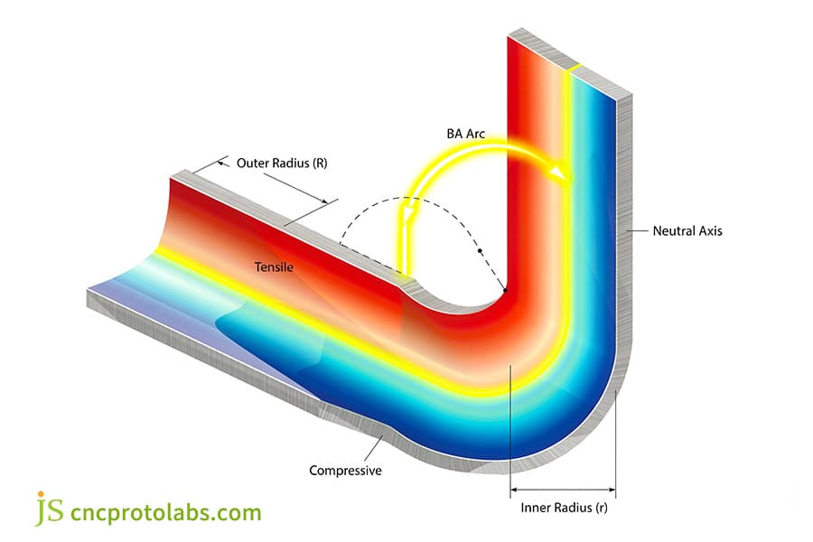
Figure 1: 3D diagram of sheet metal bending showing tensile, compressive, neutral axis, and BA arc.
How do air bending sheet metal vs bottom bending tooling shift the neutral axis?
Sheet metal bending methods selection governs neutral axis migration. In air bending sheet metal, the sheet contacts only the punch tip and die shoulders, driving the neutral axis inward(K≈ 0.30 to 0.38). Conversely, bottom bending tooling forces full die cavity conformance under high tonnage, compressing the cross-section and pushing the neutral axis outward(K≈ 0.45 to 0.50).
Stress Distribution in Air Bending vs Bottom Bending
- Empty bending: Three-point loading, punch insertion, low carbon steel K=0.30–0.38, aluminum 0.33–0.40.
- Bottoming: The material conforms to the die radius; the required force is 2–3× that of air bending, and K = 0.45–0.50.
- Coining: The neutral axis is centered at about K ≈ 0.50.
- Risk: using a wrong bending method in the CAD software and actually doing it in the workshop can cause the flange system to be systematically too long or too short.
V-Opening Ratio and Tonnage Impact
For air bending sheet metal vs bottom bending tooling, V-opening control K stability:
- V=6T → K≈0.35, high tonnage, high rebound.
- V=8T → K≈0.38, balanced open bend, applicable to 5052-H32 and SPCC.
- V=10T → K≈0.40, low tonnage, more radial tension.
- The pressure base increases by 2–3 times the tonnage, and K shifts upward by 0.07–0.12.
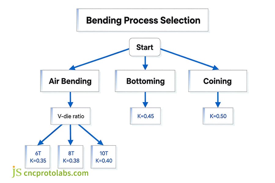
Figure 2: Bending process selection flowchart showing air bending, bottoming, coining, and K values.
Why does bending stainless steel sheet metal vs bending aluminum sheet require different allowances?
Bend expansion is mainly influenced by material ductility and strain hardening. Bending of stainless steel sheet metal, with a 40% elongation rate and large springback (3° to 5°) calls for a high K-factor (K≈ 0.42 to 0.48). Still, bending aluminum sheet (e.g. 5052-H32) with lower ductility results in the neutral axis being shifted farther inward (K≈ 0.35 to 0.40).
Ductility and Springback of Stainless Steel vs Aluminum
- 5052-H32 Aluminum: 2.0 mm, tensile strength ≥210 MPa, elongation ≈12%, springback 0–1°, K=0.36–0.38.
- 304 stainless steel: 2.0 mm, tensile strength ≥515 MPa, elongation ≈40%, springback 3–5°, K=0.44–0.45.
- Shared risk: a single K-factor may overestimate the aluminum flange length and underestimate the stainless-steel springback.
Cold-Rolled Sheet Grain Direction Impact
The bending direction impact on K-factor across cold-rolled sheet grain is significant and must be considered.
- Lateral bending: Uniform plastic deformation, K≈0.38, no cracks.
- Longitudinal bending: offers resistance but cracking may happen, K falls to 0.33, a compensation of 0.15–0.35 mm is needed.
- Example: A 1.5 mm SPCC will be cracked when longitudinally bent with a bending radius (R/T) of less than 1.2, but will not crack when bent transversely with a bending radius (R/T) of 1.0.
90° Air Bending Quick Reference Table
|
Material |
T (mm) |
V‑Opening |
R (mm) |
K‑Factor |
90° BA |
Springback |
|---|---|---|---|---|---|---|
|
5052‑H32 |
1.5 |
12 (8T) |
1.6 |
0.38 |
3.41 mm |
0–1° |
|
6061‑T6 |
2.0 |
16 (8T) |
2.5 |
0.36 |
5.06 mm |
1–2° |
|
SPCC |
2.0 |
16 (8T) |
2.0 |
0.40 |
4.40 mm |
1–2° |
|
304 2B |
2.0 |
16 (8T) |
2.0 |
0.45 |
4.55 mm |
3–5° |
|
1018 CR |
2.0 |
16 (8T) |
2.0 |
0.41 |
4.52 mm |
1–3° |
Data Source: ASTM E8/E8M‑22 – tensile elongation testing for sheet alloys
For the same 8T opening, the K value of stainless steel is 0.07-0.10 higher than that of aluminum alloy.
Engineering Case Study: 304 Stainless Steel Control Panel
1.5 mm 304 stainless steel housing, four 90° flanges, tolerance ±0.15 mm.
- Problem: When using an aluminum K-factor of 0.38, the flange is 0.42 mm too long, causing interference with hole positions.
- Correction: Switch to a K-factor of 0.44 and orient the bend line perpendicular to the rolling direction.
- Result: Dimensions stabilized within ±0.08 mm.
Need a faster path from alloy selection to press brake setup? Contact a JS Precision engineer for a free DFM review of your stainless steel or aluminum bend drawings.
How do sheet metal bending calculation standards align with factory tolerances?
Industry standards require thorough boundary checking. Per the ANSI/ASME Y14.5 and ISO 2768-m standards, accurate bends must meet ±0.1 mm linear tolerances. Yet, using bending calculation of sheet metal based purely on theoretical models, without considering heavy-gauge tonnage, will result in thinning and an empirical bend deduction calculator will need to surpass theoretical formulas.
Heavy-Gauge Bending Force Deviation
Steel bending force calculator deviations occur in heavy-gauge plate bending which introduces nonlinear errors:
- Thin-rolling: When the plate thickness exceeds more than 6 mm, under-loading causes local 5–8% thinning.
- Theoretical deviation: With K = 0.50, the formula overestimates the flat length; for an 8 mm plate the deviation exceeds 0.5 mm and measured thinning reaches 5–8%.
- Actual measurement: 8 mm S355, R=12 mm, V=64 mm empty bend, K=0.46, 6% thinning and BD should be corrected by −0.62 mm compared to theoretical BA.
Practical Unfolding Workflow
- Obtain the material thickness T, which is ±0.05 mm according to ASTM A480.
- Select the process and record the V-opening ratio: 6T–10T.
- Load the verified K-factor; convert Creo to Y-factor.
- Calculate BA and BD for each bend.
- When T>6 mm, use an empirical subtraction chart containing a thinning factor of 5–8%.
- Release the test sample after CMM verification confirms it is within ±0.1 mm.
FAQs
Q1: How do you calculate bend allowance vs bend deduction for 90-degree air bending?
For a 90-degree bend, bend allowance (BA) gives the flat length along the neutral axis as BA=(π/ 2) X(R+K X T). Bend deduction (BD) then again estimates the material removed from the flat stock as BD = 2 X OSSB - BA where outside set back (OSSB) = R + T. CAD software typically employ BA to create the 3D model while shop floor operators prefer BD to directly measure and verify the cuts length of sheared workpieces.
Q2: When should engineers choose K-factor vs Y-factor in CAD unfolding?
This is really a matter of the CAD architecture. The use of K-factor by the engineer is the norm when using SolidWorks, Autodesk Inventor, or CATIA since the calculation engines of all these systems refer to K as a proportion of depth (t/T). But, Y-factor is the native calculation standard of PTC Creo (Pro/ENGINEER), because it weighs neutral axis arc ratio directly. But, both flat layouts will look similar when the formulas are converted through Y = K Xπ/2.
Q3: Why does bending allowance differ between bending aluminum sheet and stainless steel?
Raise material yield strengths and strain hardening exponents account for the difference. Bending 304 stainless steel which is strong in tension and springback (up to 5°) will keep the K factor higher(K≈0.45). But, 5052-H32 aluminum which starts yielding sooner with very little increase in strength will shift the neutral line much deeper inside(K≈0.38). If you use the same value for the allowance, the aluminum flanges will get longer while stainless steel pieces will under-bend.
Q4: How does sheet metal grain direction affect K-factor during air bending?
Cold-rolled sheets have a stretched grain structure that is parallel to the rolling direction. Bending across the grain results in maximum resistance to cracking and plastic deformation being almost uniform so K-factor remains predictable(K≈ 0.38) whereas bending along the grain reduces deformation resistance but increases cracking probability because of this pushing the neutral axis closer (K≈ 0.33) to inner radius and changing flat blank length up to approximately ±0.35 mm.
Q5: Can you safely assume K-factor is always 0.33 for precision sheet metal?
Considering only K=0.33 as a constant is justified if you air bend a soft sheet at a small radius. However, once you switch to bottoming (K → 0.50) or form high-strength alloys with punch radii above 2×T, the K-factor can rise to 0.45. You should know that relying on one fixed 0.33 value throughout the different tasks causes severe errors so empirical test bendings must be done for accurate tolerancing.
Summary
Factors like K factor, Bend Allowance, and Y factor form the primary sequence of controlling sheet metal development for unfolded parts: CAD design values have to be closely matched with workshop processes (air bending/pressing) and material properties. The main purpose here is to get the most accurate calculations and to perform actual bending experiments that not only reduce prototyping costs but also guarantee assembly tolerances ±0.1mm.
To ensure assembly-ready accuracy across precision manufacturing projects, design teams can compare custom sheet metal bending capabilities at JS Precision or download our engineering reference tables. For demanding designs requiring tight form-fit alignment, review verified precision sheet metal bending tolerances at JS Precision and consult our technical specialists for direct DFM sheet metal feedback.

Disclaimer
The contents of this page are for informational purposes only. For JS Precision Services, there are no representations or warranties, express or implied, as to the accuracy, completeness, or validity of the information. It is the buyer's responsibility to identify specific technical requirements and request a formal parts quotation. Please contact us for more information.
Resource

