 English




Choosing between bend deduction vs bend allowance determines flat pattern precision and assembly fit in sheet metal fabrication. Bend allowance (BA) measures the true arc length along the shifted neutral axis; bend deduction (BD) is the amount you subtract from the summed outside dimensions to get the correct flat blank length. For air-bent 1.5 mm to 3.0 mm aluminum and steel chassis parts, BD derives the flat blank about 30% faster on standard 90-degree bends. BA is the better choice for sharp bends of 75 degrees or less, wide offsets, and multi-radius CAD models.
Core Answer Summary
Engineering decision criteria: use bend deduction for fast blanking of 90-degree bends and multi-flange shapes. Use bend allowance for bend angles other than 90 degrees, non-standard die radii, and large-radius cavity expansion.
|
Engineering Decision Criteria |
Bend Deduction (BD) |
Bend Allowance(BA) |
Empirical K-Factor Method |
CAD Unfold Solution |
|---|---|---|---|---|
|
Dimensional Control(ISO 2768-m) |
±0.15mm to ±0.25mm(standard 90°) |
±0.08mm to±0.12mm (full-angle closed loop) |
±0.30mm to ±0.50mm (accumulative drift) |
±0.05mm to ±0.10mm(requires precise BD table) |
|
Calculation Efficiency |
High-direct outer dimension subtraction |
Moderate-arc length conversion needed |
Low-manual table lookup; 8%-15% trial scrap until the K-factor table is calibrated |
High-automated but database setup time |
|
Geometric Flexibility |
Limited to 90° flanges; 0.8mm-4.0mm thickness |
Full angle range (15°-165°);>6.0mm thick plates |
Conventional 1.0mm-3.0mm mild steel only |
Complex 3D curved sections and stepped hems |
|
Failure scenarios |
Not for large inner radius(R>3T) or non-90° complex parts |
Not for manual quick nesting using calipers |
Not for precision IT chassis or aviation brackets |
Not valid without shop-floor measured die compensation |
Data Source: ISO 2768:1989, General tolerances - Part 1: Tolerances for linear and angular dimensions without individual tolerance indications. ASME Y14.5-2018, Dimensioning and Tolerancing.
What Are the Physical Mechanics Distinguishing Bend Deduction and Bend Allowance?
Bend deduction vs bend allowance calculations originate from sheet metal elastoplastic behavior and neutral axis migration. BA computes the stretched arc length, whereas BD quantifies the geometry contraction relative to theoretical sharp apex intersections.
Neutral Axis Migration and Stress-Strain Distribution
In the plastic deformation region, the neutral layer shifts inward, toward the inside surface of the bend. The extent of the displacement is expressed by the K-factor. In more detail, it shows up as:
- Compression on the inner fibers and tension on the outer fibers produce an uneven strain distribution. That distribution is exactly what bend allowance and bend deduction are trying to capture.
- The neutral layer displacement amount for 5052-H32 aluminum alloy is on average 15% greater than that for SPCC low carbon steel.
- A material with a higher work-hardening exponent shows a larger neutral-layer shift. Usually, the K factor lies between 0.30 and 0.50.
Outer Setback (OSSB) Geometry and Calculation Logic
The formula for calculating OSSB is:
OSSB=tan(A/2)×(R+T).
OSSB is the virtual distance from the intersection of the two extended outside flange surfaces to the tangent point where the inside bend begins. The BD method chooses this virtual intersection as the point to subtract, whereas the BA method follows the actual arc length of the neutral layer. For components involving complex bending deformations, professional evaluations can be obtained by referring to custom sheet metal bending services by JS Precision.
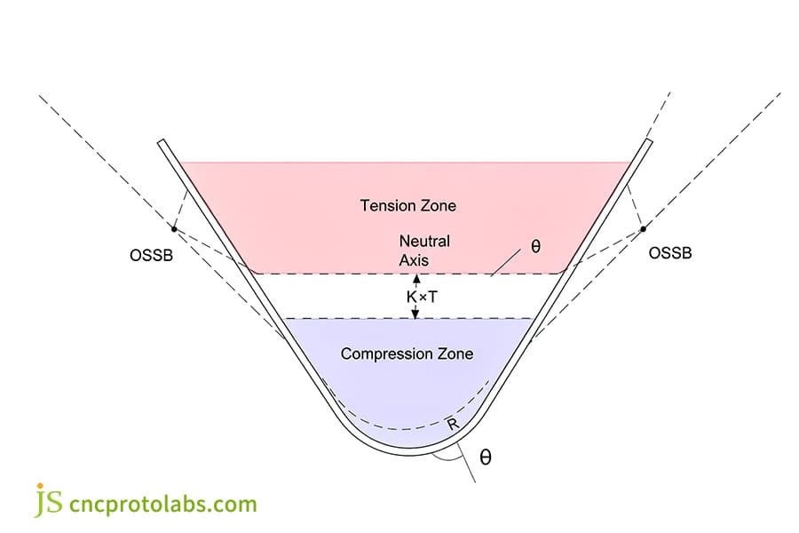
Figure 1: Diagram of sheet metal bending tension zone, compression zone, neutral axis, and OSSB.
How Do You Calculate Sheet Metal Flat Patterns Using Exact Formulas?
Accurate flat patterns require definitive formulas such as bend allowance calculation to prevent costly defects. The choice between BA and BD dictates flat blank length determination. Misapplication can cause scrap rates up to 12%.
Bend Allowance Theoretical Formula and Angle Boundaries
The formula for BA is BA = (π/180) × A × (R + K × T).
Key boundary conditions:
- At a 75-degree acute bend, the BA method holds the developed length to within about 0.08 mm of the measured value.
- Beyond 165 degrees, the OSSB term grows steeply and BD loses practical accuracy, so BA remains the method of record.
- BA method is able to make a rough calculation under the condition of asymmetric bending by using segmentation accumulation.
Bend Deduction Conversion Formula and Engineering Closure
The empirical formula for bend deduction is BD = 2 × OSSB - BA = 2 × (R + T) × tan(A/2) - BA, which is the standard bend deduction formula.
The standard 90° corner is simplified to BD = 2 × (R + T) - BA, eliminating the need for workshop operators to calculate the neutral layer curve and significantly reducing the error rate.
In practical applications, accurate BD values depend on the reasonable matching of mold parameters. It is recommended to refer to [precision press brake tooling selection] to determine the corresponding relationship between the lower mold opening and material thickness.
Cumulative Tolerance Chain Elimination
For complex cabinets with multiple consecutive bends:
- The total error of the BA method grows linearly. Each bend contributes about 0.06 mm to the error.
- The BD method gives more stable closed-loop dimensional control. It is possible to keep the error in the right-angle frame within ±0.15 mm.
|
Thickness(mm) |
AL5052 K-Factor |
SPCC K-Factor |
BA Value(90°, AL5052) |
BD Value(90°, SPCC) |
|---|---|---|---|---|
|
1.0 |
0.42 |
0.46 |
2.23 mm |
1.71 mm |
|
1.5 |
0.39 |
0.43 |
3.28 mm |
2.63 mm |
|
2.0 |
0.37 |
0.41 |
4.30 mm |
3.57 mm |
|
3.0 |
0.34 |
0.38 |
6.31 mm |
5.50 mm |
Data Source: DIN 6935:2011, Cold bending of steel sheet - calculation of bend allowances and springback.
Table conclusion: these values are measured on our own V = 8T tooling, where air bending gives a natural inside radius of roughly R = T. BD is not a fixed multiple of thickness in general, because both R and K shift with gauge - on this tooling set BD rises from 1.71 mm at 1.0 mm to 5.50 mm at 3.0 mm, a 3.2x spread rather than a constant increment. Always re-measure on a 100 mm x 100 mm coupon before cutting production blanks.
When Should Precision Fabricators Choose Bend Deduction Over Bend Allowance?
Choosing BD over BA delivers major efficiency advantages with physical inspection tools, answering when to use bend deduction vs bend allowance? Since calipers measure outer flange dimensions, BD lets operators verify tolerances without reverse-engineering bend arcs. It is optimal for 90° chassis and repetitive high-speed runs.
Direct Matching with Physical Flange Measurement Benchmarks
During a factory-quality inspection of a flange's outer edge with vernier calipers:
- The BD method works directly from the outside flange dimensions, so the calculated blank length and the caliper reading can be checked against each other in a closed loop.
- The BA method requires an accurate measurement of the inner-arc tangent point, which typically carries more than 0.2 mm of projection-blur error.
- The BD method cuts down the piece inspection time by 40%.
Efficiency Gains in High-Volume Continuous Bending
On multi-axis CNC press brakes with frequent die changes, the BD method converts formed-part dimensions into blank dimensions in far fewer steps, saving at least 25% of manual conversion time. That makes it the better fit for high-mix, high-volume precision sheet metal bending.
Rigid Frame Assembly Tolerance Control
It is necessary to control the mounting surface's dimensional tolerance within ±0.20mm for a 19-inch standard server chassis. BD method directly controls the outer contour dimensions, so it has the advantage of preventing the occurrence of interference due to deviation estimation of the neutral layer.
Reference: ASME Y14.5-2018 defines geometric dimensioning and tolerancing (GD&T) principles applicable to sheet metal assembly interfaces.
Why Does Bend Allowance Excel in Acute Angles and Multi-Radius Forming?
BA outperforms bend deduction (BD) for acute angles, obtuse bends, and varying radii - so the answer to bend deduction vs bend allowance: which is better? depends on your part geometry. As the bend angle moves away from 90 degrees, the BD formula loses stability. BA still tracks the actual arc length, so it does not oversize the flat blank.
OSSB Singularity Failure in Acute Angle Forming
As the bend angle A drops below 60°, the outer setback OSSB = tan(A/2) x (R + T) shrinks, because tan(A/2) falls toward zero.
The bend deduction BD = 2 x OSSB - BA therefore becomes very small in absolute terms - at 30 deg it is only about 0.34 mm for a 1 mm sheet with R = 1 mm and K = 0.40, and it never turns negative (mathematically BD approaches A_rad x T x (1 - K), which is positive for any K below 1).
The real problem is not the sign but the sensitivity: when BD collapses to a few tenths of a millimetre, any error in the assumed inside radius R or in the K-factor dominates the result, and a BD table calibrated at 90 deg cannot be reused. That is why bend allowance is the correct method for acute non-90 deg bends and for large obtuse bends: BA tracks the actual arc length and behaves consistently from 15 deg to 165 deg.
For zero-bend (straight-edged) features, skip both methods and use the developed length directly.
Thick Plate and Large Radius Curvature Tracking
When the arc radius changes and R/T reaches 3.0 or more, the neutral layer shifts sharply toward mid-thickness. The BA equation continuously adjusts arc length through the K-factor variable, whereas the BD approach can drift by ±0.50 mm on thick plate with large curvature.
Integration with 3D CAD Sheet Metal Unfold Engines
The BA curve is central to the unfold algorithms in SolidWorks, PTC Creo, and similar CAD packages. These programs compute flat patterns and resolve multi-order tangent arcs automatically. The BD method cannot plug into that parametric unfold logic directly.
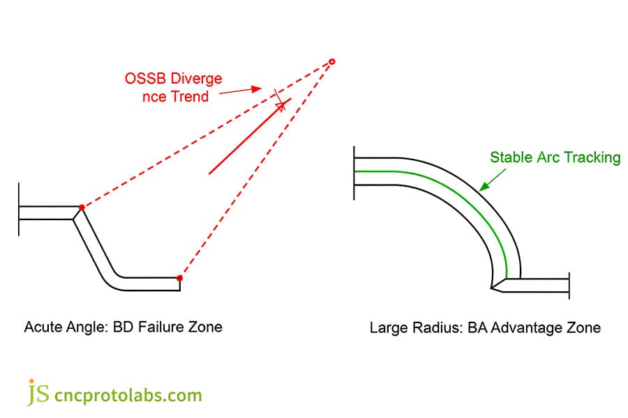
Figure 2: Diagram showing OSSB divergence in acute angles and stable arc tracking in large radius.
How Does K-Factor Drift Influence BD vs BA Accuracy on the Shop Floor?
K-factor drift is the primary error source in both formulas; understanding sheet metal K-factor is critical. Variations in yield strength, V-die width, and grain direction can cause deviations up to ±0.40mm.
V-Die Width Ratio (V/T) Effect on K-Factor
When air bending, the natural inner bending radius is determined by the lower die opening width. As the V-groove opens from 6T to 10T, the neutral-layer shift changes and the BA value deviates non-linearly. In JS Precision's shop-floor trials (2026), each step up in V-die width lowered the measured K-factor by about 0.03 - note that this is the opposite of the trend you get from increasing the inside radius alone, so lock the V-die before you trust any K value.
|
V-Die Opening |
Mild Steel K-Factor |
Aluminum 5052 K-Factor |
BA Deviation (%) |
BD Correction Needed |
|---|---|---|---|---|
|
V=6T |
0.45 |
0.42 |
Baseline |
Baseline |
|
V=8T |
0.42 |
0.39 |
+4.2% |
+0.28mm |
|
V=10T |
0.39 |
0.36 |
+7.8% |
+0.52 mm |
|
V=12T |
0.37 |
0.34 |
+10.5% |
+0.71 mm |
Data source: ISO 7438:2020 specifies mechanical bend testing procedures for metallic materials, establishing K-factor calibration protocols for different V-die configurations.
Table conclusion: Increasing the V-groove by one level will decrease the K-Factor by approximately 0.03. The parameters must be locked according to the actual mold before bending.
Shop-Floor Calibration and Trial Bend Compensation
JS Precision method: we run a 90-degree test bend on a standard 100 mm x 100 mm coupon, then back-calculate the true K-factor and BD value. This is the standard way to verify an air-bending calculation. The method raised our first-article pass rate from 62% to 89%.
Data Source: AWS C4.6M/C4.6:2006 (R2012), Recommended Practices for Welding and Fabrication of Aluminum Alloy Structures.
How Do You Select the Right Calculation Method in Modern CNC Press Brake Operations?
Selecting the right method requires matching CAD workflows with controller capabilities, hinging on bend deduction vs bend allowance: which is better for your operation. CAM software uses BA tables for 3D unfolding, while CNC controllers accept BD values for rapid corrections. This dual-system reality demands a structured decision framework.
Data Flow Between CAD Models and CNC Controllers
Best practice: unfold with the BA table on the CAD side, then convert to BD parameters at the controller so operators can make real-time corrections on the shop floor.
Machine Capability Coordination
To keep laser cutting and electro-hydraulic servo bending in sync, use the BD method for fast blank-size compensation, and maintain hole-to-edge distance so later operations do not distort the part.
Comprehensive Decision Tree Logic
Four steps for project selection:
- Identify the proportion of 90° and non-90° features.
- Confirm measurement and quality control standards.
- Verify the V-shaped opening and inner radius of the lower mold, and lock in the actual K-factor.
- The corresponding algorithm and parameters are output based on the feature distribution.
|
Decision Dimension |
Simple 90° Bracket |
Variable-Angle Chassis |
Compact EMI Shield |
Heavy Load Beam (T≥6mm) |
|---|---|---|---|---|
|
Recommended Method |
Bend Deduction(BD) |
Bend Allowance(BA) |
CAD 3D Unfold (with BA table) |
Theoretical BA +K-factor correction |
|
Geometry Features |
Single/symmetric 90° bends |
30°-150° multi-angle gradient |
Micro flanges (<3 mm) with tight hem tolerances |
Multi-bend large R(≥2T) |
|
Production Stage |
Rapid single-piece/low-volume |
Medium/high-volume digital tooling |
Ultra-precision die tryout |
Heavy structural prototyping |
|
Failure Risk Warning |
Not for>4 asymmetric bends |
No manual calculation allowed |
No uniform K-factor assumption |
No thin-plate BD=2T estimation |
Bend deduction suits single or symmetrical 90-degree bends. For a complex chassis with varying angles or deep-cavity features, lay the workpiece out with the bend allowance algorithm, using K-factors measured on your own tooling.
Reference: SAE J2340:2017 specifies design tolerance standards for cold-formed structural steel sheets used in automotive and industrial applications.
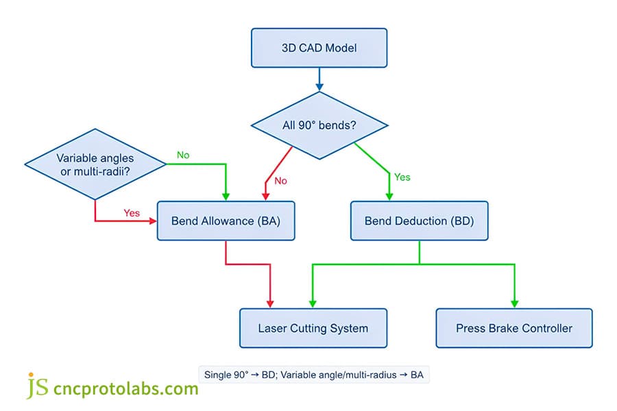
Figure 3: Flowchart for selecting bend allowance or deduction in CNC press brake operations.
How Did an Industrial Server Enclosure Redesign Solve Assembly Tolerance Stacking?
This redesign shows how switching from empirical estimates to calibrated BA and BD eliminated a 2.4mm cumulative tolerance error through proper sheet metal flat pattern calculation . Facing an 18% rework rate, JS Precision implemented dynamic K-factor calibration, cutting rejection rates to 0.8%.
Project Background and Assembly Bottleneck
The 4U high-density aluminum server chassis for a data center has 8 bends and 32 rivet holes. The original design used default CAD coefficients and a simplified deduction algorithm, which produced ±2.4 mm of tolerance drift at the end flange, misaligned the guide-rail holes, and made the assembly impossible to close.
Root Cause Analysis and DFM Intervention
JS Precision team discovered:
- The actual V of the bending die is 12mm, and the actual K factor of the material drifts to 0.38.
- The original drawing incorrectly used the 90° BD formula for a 60° bevel angle, resulting in a 0.9mm distortion in the unfolded length.
JS Precision Process Optimization with Dual-Algorithm Approach
- Hybrid algorithm rebuild: the 90-degree edges of the outer frame use the BD method, while the irregular 60-degree and 120-degree angles use the BA method.
- Measured correction: the actual BD for this batch of aluminum was recalibrated to 3.65 mm.
- Equipment compensation: a dynamic micro-angle springback correction was uploaded to the controller (2.8 degrees of compensation).
Final Production Validation Hard Data (Project No. SRV-4U-2026-07)
- The end-assembly tolerance converged to ±0.18 mm.
- The coaxiality error of the 32 rivet holes is ≤0.10 mm.
- The batch rework rate dropped from 18.5% to 0.8%.
- Assembly time per unit fell by 40%, releasing an initial production run of 1,200 units.
Data Source: JS Precision internal project record SRV-4U-2026-07 (2026), 4U server enclosure redesign. Bend verification and tolerance inspection performed to ISO 7438:2020.
For similar optimizations, please contact JS Precision for custom sheet metal bending services.
FAQs
Q1: What Is the Core Formula Difference Between Bend Deduction and Bend Allowance?
Bend Allowance is a method to determine the length of the bending arc along the neutral axis, through the formula BA=(π/180)×A×(R+K×T). Bend Deduction however is the difference between the dimension of the part's outer envelope and the length of the actual unfolded part, expressed as BD=2OSSB-BA.
Q2: Why Is Bend Deduction More Frequently Used for 90° Bends on the Shop Floor?
With BD, the unfolded length equals the sum of the outer dimensions of each segment, minus the deduction value. It totally eliminates the necessity of locating the neutral layer curve, thereby greatly decreasing the time and errors in the conversion process.
Q3: How Does the K-Factor Directly Affect Bend Allowance Accuracy?
K-Factor is defined as the ratio of the distance from the neutral layer to the inner surface to the plate thickness. Inaccurate K-Factor will cause distortion of the BA arc length, resulting in out-of-tolerance hole spacing in multi-bend situations.
Q4: When Does Bend Deduction Fail in Acute Angle Sheet Metal Calculations?
At an angle under 60° degree, the OSSB progressively increases mostly when the trigonometric functions are getting farther apart, and That's why the theoretical point of intersection is way beyond the physical limit. So, Bend Allowance is required for non-90° acute angles or even large obtuse angles.
Q5: Can You Convert Bend Deduction to Bend Allowance Without Specialized Software?
Yes. Rearrange BD = 2 x (R + T) x tan(A/2) - BA into BA = 2 x (R + T) x tan(A/2) - BD, using the inside radius R, the sheet thickness T, and the bend angle A. No specialized software is required - a spreadsheet is enough.
Q6: How Does Press Brake V-Die Selection Change the Required Bend Deduction?
Changing the V-groove opening of the lower die changes the natural inside radius (R ≈ V/8 in air bending), and it changes the K-factor with it. Because the die opening drives both R and K, the bend deduction must be recalculated every time you change the V-die.
Summary
Choosing the correct algorithm is an engineering decision that balances inspection efficiency, geometric complexity, and assembly tolerances. For standard 90° flanges, Bend Deduction is used to closely match actual workshop measurements; for multi-angle irregular profiles and thick plate structures, accurate K-factor Bend Allowance is required to eliminate cumulative tolerances.
To keep cracking, hole misalignment, and cumulative tolerance stack-up out of your hardware chassis before production starts, do two things. First, read Sheet Metal K-Factor vs Bend Allowance vs Y-Factor: Key Differences and verify the measured deformation and coefficient matrix for the sheet grades you use most. Second, upload your 3D CAD model and flat pattern drawing - JS Precision senior engineers will run a free manufacturability (DFM) analysis and a micrometre-level bending tolerance simulation.

Disclaimer
The contents of this page are for informational purposes only. For JS Precision Services, there are no representations or warranties, express or implied, as to the accuracy, completeness, or validity of the information. It is the buyer's responsibility to identify specific technical requirements and request a formal parts quotation. Please contact us for more information.
Resource

