English



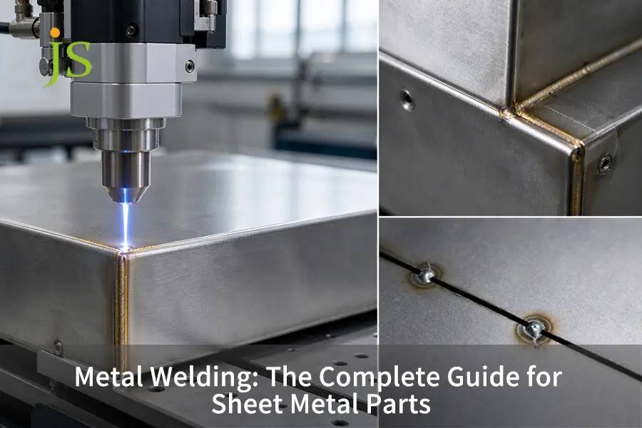

Sheet metal welding involves the thermal fusion of thin metal sheets, generally ranging from 0.5 mm to 6.0 mm in thickness, by applying focused heat from an electric arc, resistance, or laser beam to join seams without burning through the base metal. In precision sheet metal fabrication, managing heat input is the most crucial factor to avoid part warping and weld defects in the structure. TIG and continuous fiber laser welding are commonly used for tight-tolerance enclosures with tolerances between 0.2 mm and 0.5 mm, whereas MIG and resistance spot welding provide faster cycle times suitable for structural brackets and high-volume production.
Primary Sheet Metal Welding Process Comparison
Thermal input control is a critical factor in thin-sheet processing: Less than 1.5 mm sheet metal must use fiber laser welding or pulsed TIG, over 2.0 mm sheets can use MIG welding, and overlapped flanges use resistance spot welding.
| Welding Process | Optimal Sheet Thickness | Warping Risk | Joint Strength & Sealing | Secondary Finishing Cost | Recommended Applications |
| Fiber Laser | 0.5 mm – 3.0 mm | Extremely Low (HAZ ≤0.5 mm) | Hermetic seal, parent-metal tensile strength | <5% (no spatter, minimal dressing) | Precision electronics, battery trays, medical chassis |
| TIG (GTAW) | 0.8 mm – 4.0 mm | Moderate (requires copper chill blocks) | High structural strength, superior cosmetic bead | 15% – 20% (light surface blending) | Architectural panels, food-grade equipment, visible enclosures |
| MIG (GMAW) | 1.5 mm – 6.0 mm | High (heavy line heat input) | Deep root penetration, high shear load | 30% – 40% (grinding spatter & proud beads) | Heavy industrial brackets, base plates, equipment skids |
| Spot Welding | 0.6 mm – 3.0 mm (lap joints) | Low overall, localized surface indentations | High shear strength, non-watertight | 0% (paint-ready right off machine) | Sheet overlap seams, stiffener ribs, server rack cabinets |
Need certified tolerance and quality seam welding of custom enclosures? Upload your 3D CAD files for a quick and easy Design for Manufacturability assessment by JS Precision.
Why Does Sheet Metal Welding Warp and Burn Through?
Sheet metal welding causes warping and burn-through because thin plates under 2.0 mm have limited mass to absorb concentrated heat. When heat input goes beyond about 0.35 kJ/mm, rapid thermal expansion creates strong compressive stress in the surrounding metal. As the molten weld pool cools and contracts, residual tensile stresses cause the thin sheet to buckle. Maintaining steady travel speeds and applying heat sinks are essential to keep dimensional tolerance within ±0.2 mm.
Understanding Thin-Plate Heat Dissipation
For thick structural steel greater than 8.0 mm, heat is dissipated in three dimensions within the mass of the cold plate. For thin sheet metal welding, heat is transferred strictly in two dimensions along the surface. Since heat cannot transfer in the down direction, the localized weld seam becomes superheated very quickly. If the arc is moving less than 0.15 meters per minute, the joint temperatures can exceed 1,400 °C while nearby metal is near room temperature.
Such a thermal gradient causes the expansion of the heated portion. However, it becomes physically constrained due to the cooler parent plate which forms the boundaries for this heating portion, resulting in compression forces acting on the heated part that quickly surpass its yield point under increased temperature. As the molten puddle cools, tensile forces cause warping of the metal sheet.
Reviewing the fundamental metal welding process enables fabricators to balance arc parameters against base sheet thickness before striking an arc.
Root Causes of Edge Burn-Through
Burn-through happens when the depth of molten pool is more than the thickness of the sheet before the torch moves forward:
- If the arc is stationary for more than 0.3 seconds, the burn-through of sheets that are less than 1.2mm thick happens instantly.
- Fitting gaps of greater than 0.1mm create spaces from which the metal can be supported, causing molten edges to split and form holes.
- Outside corners burn twice as fast as flat spots since the heat dissipates through two open sides rather than one.
- Improper positioning of the ground clamp induces magnetic arc blow, which results in an electric arc blowing towards thin edges.
- Overdriving tension in the feeder causes the filler wire to puncture the puddle floor.
Avoiding Welding Straightening Bottlenecks
Warped thin gauge parts cause costly delays in the production process. Warping of 1.5 mm in a 400 mm frame takes 20 to 45 minutes of manual shrinkage, press-brake straightening, or hand planishing per piece.Managing thermal energy upstream and applying rigid clamping eliminates the need for mechanical straightening after metal welding, ensuring compliance with ISO 3834-2:2021 quality requirements.
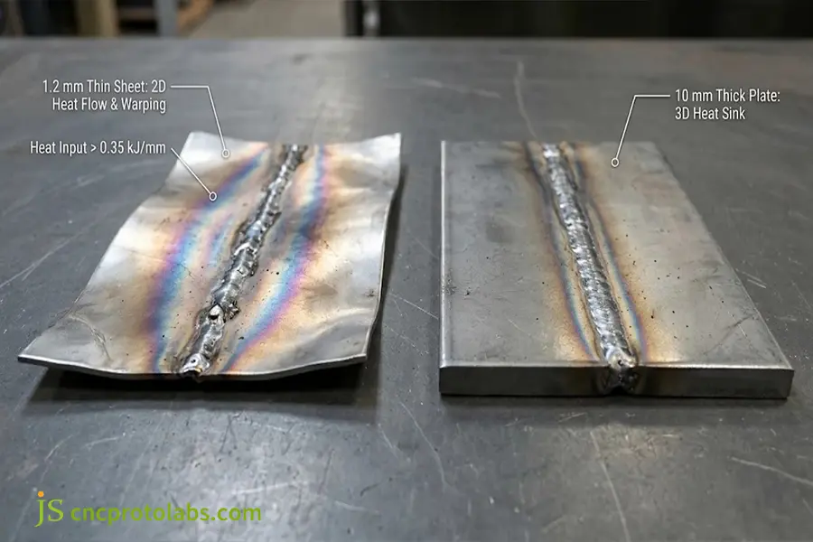
Two-dimensional heat concentration causes severe bowing in 1.2 mm thin sheets compared to 3D thermal dissipation in 10 mm plates.
How Does the Metal Welding Process Work on Thin Sheets?
The sheet welding process uses chemical surface cleaning, precision clamping and fixation welding to position during all preparations, laying the main bead. The core process parameters include welding current (20 to 120 A based on the thickness of the sheet), welding speed (0.2 to 2.5 m / min), and argon flow rate (10 to 18 L/min). The arc distance of less than 1.5 mm is maintained to ensure a stable arc and avoid porosity and base sheet overheating.
Removing Contaminates Prior to Arc Strikes
Thin sheets have large surface-area-to-volume ratios surface oxides and oils should be why for joint rejection:
- Carbon Steel (SPCC): Remove oil contaminates using either solvent wiping or ultrasonic degreasing.
- Stainless Steel: Remove the scale left from air laser cut by grinding the metal with fine abrasive wheels.
- Aluminum Alloys: Brush off the 2,072 °C surface oxide skin using a clean stainless steel wire brush right before executing any metal welding process.
- Pre-Coated Sheets: Remove temporary protective polymer films at least 25 mm back from the seam line before welding to prevent plastic char burn-in to the weld pool.
Fixturing with Copper Chill Bars
Structure does not provide sufficient stiffness of the part under thermal load. Anchor and clamp assemblies in a stationary fixture with copper chill blocks behind:
- The heat conductivity of copper is around 390 W/(m·K), which makes it possible to extract maximum heat twenty times faster than stainless steel.
- The clamping of a copper chill bar beneath the weld line will help remove heat from the root and solidify the molten puddle before sagging occurs due to the force of gravity.
- A shallow relief groove (0.2 mm deep x 1.5 mm wide) is machined into the face of the copper bar. It is removed along the entire length of the wire, because of this enabling consistent underside bead penetration with molten metal not dropping through.
- Using pneumatic edge hold-down fingers placed within 5 mm of the seam edge helps prevent thin edges from lifting and disrupting arc focus during travel.
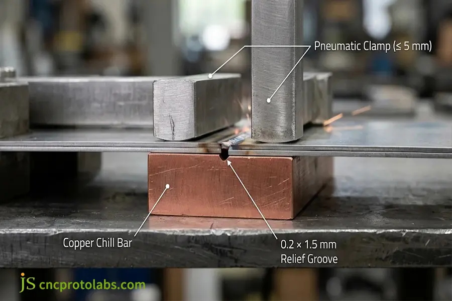
Pneumatic hold-down clamps positioned within 5 mm of the joint paired with a grooved copper chill bar to draw peak heat out of the weld root.
Setting Parameters and Gas Coverage
The pulsed arc method and the laminar flow of gas ensure root integrity:
- Current Control: Operate within the range of 20 to 120 A, depending on the gauge, not to burn through.
- Travel Speed: Torch speeds should be between 0.2 and 2.5 m/min to reduce the line energy.
- Gas Flow: Is 10 to 18 L/min of pure argon (99. 995%) flowing through a gas lens to reduce porosity.
- Pre-Flow and Post-Flow: Use 0.5 seconds of pre-flow time to get rid of atmospheric air followed by 3.0 to 5.0 seconds of post-flow time to protect the cooling tungsten electrode and melting pool crater from the heat.
- Electrode Shape: The 2% ceriated or lanthanated tungsten electrodes need to have a shape of 30° to 45° included angle with a flat 0.2 mm tip. It focuses the arc energy in an ultra-narrow heat channel.
- Quality Acceptance: Good coverage helps avoid porosity and oxidation defects according to AWS A3.0 metal welding standards.
What Are the Most Common Weldable Metals for Sheet Metal?
Weldable metal types for sheet metal welding the typical metals most often weldable for sheet metal welding are carbon steels, stainless steels (304, 316L) and aluminum alloys (5052, 6061). Among those, low-carbon steels are easiest to weld with usual equipment, while stainless steel needs low heat and avoiding carbide precipitation and bowing. Aluminum needs pulse TIG or fiber laser welding to melt the aluminum surface oxide layers and prevent hot cracking, while galvanized sheet needs zinc removal along the weld line.
Sheet Metal Weldability and Filler Wire Matrix
The choice of base materials and compatible filler alloys involves a compromise between heat conductivity and propensity for cracking:
| Material Grade | Weldability Rating | Compatible Filler Wire | Shielding Gas Mix | Key Fabrication Consideration |
| SPCC / Mild Steel | Excellent | ER70S-6 | 100% Ar or 80/20 Ar/CO2 | Requires prompt surface coating to stop rust |
| AISI 304 / 304L | Very Good | ER308L | 100% Argon + purge | Keep interpass temperature ≤150 °C |
| AISI 316L | Very Good | ER316L | 100% Argon + purge | High resistance to hot chemical corrosion |
| Aluminum 5052-H32 | Good | ER5356 | 100% Argon (high purity) | Requires wire brushing to remove oxide film |
| Aluminum 6061-T6 | Moderate | ER4043 / ER5356 | 100% Argon | HAZ strength drops 30% to 40% post-weld |
| Galvanized Steel | Fair | ER70S-6 | 80% Ar + 20% CO2 | Zinc must be ground back 10 mm from joint |
Material Characteristics on the Shop Floor
Thermal characteristics control the response of each alloy during fusion:
- Low-Carbon Steel (SPCC): Welds cleanly with laser, TIG, and MIG processes with ER70S-6 wire, but must be powder coated or plated soon after welding to avoid rusting.
- Austenitic Stainless (304/316L): Expands 50% faster and retains heat than carbon steels, necessitating 304L/316L grades, inter-pass temperature less than 150 °C, and argon back-purge gas.
- Aluminum 5052-H32: Rapidly absorbs heat and contracts during the cooling process, but welds effectively with the ER5356 filler metal.
- Aluminum 6061-T6: Cracks readily during autogenous welding, using ER4043 or ER5356 wire to dilute the melt pool, local yield strength is reduced by 30% to 40%.
- Galvanized Steel: The zinc coating on steel will boil at 906 °C, necessitating manual grinding 10 mm away from the joint in order to prevent porosity and spattering.
Thermal performance baselines align with standard physical property data published by the National Institute of Standards and Technology (NIST).
How to Select the Right Types of Welding for Metal Joining?
Selecting the right types of welding depends directly on metal thickness, order volume, and aesthetic needs. Welding by handheld and robotic laser produces the cleanest joints and the least amount of deformation for sheet materials in the range from 0.5 mm to 2.5 mm. TIG welds produce aesthetically pleasing joints on the exposed surfaces of stainless steel parts using relatively low traveling speed. MIG welding is used for structural brackets that are thicker than 2.0 mm.
Process Selection Breakdown
The choice of different metal joining methods depends on a comparison between the deposition rate of the equipment and secondary finishing:
- Fiber Laser Welding: 0.2 mm–0.6 mm beam spots at 1.0 m/min–3.0 m/min travel speeds with laser vs TIG heat-affected zone of less than 0.5 mm to prevent warping of the panels. Fit-up gaps must not exceed 0.1 mm.
- TIG Welding (GTAW): Produces better bead appearance on stainless enclosures, but comparing MIG vs TIG welding show travel speeds are slower (0. 1 0. 3 m/min).
- MIG Welding (GMAW / CMT): Performs well on structural subframes thicker than 2.0 mm, based on laser vs MIG weld strength tests that revealed deep root penetration. Comparing MIG, TIG, and Stick welding reveals CMT wire retract technology is used to join thin sheets with little spatter.
- Resistance Spot Welding (RSW): Provides immediate nuggets on overlapping surfaces in 0.1 to 0.4 seconds, with production standards of spot and resistance welding revealing no cost for wire on non-sealed panels.
Thickness-Based Process Selection
Match part thickness to currently available types of welding and pay for secondary finishing on the line:
- Select either fiber laser or pulsed micro-TIG with copper chill blocks for sheets that are less than 1.5mm thick to prevent burning through the material.
- Use fiber laser, TIG, or resistance spot welding on sheets 1.5 mm to 3.0 mm based on cosmetic requirements.
- Change to pulsed MIG or regular arc welding for materials thicker than 3.0 mm in order to ensure complete root penetration.
Want to verify if the process is right for your part run? Send your production drawings to JS Precision for an engineering evaluation of setup, cycle times and finishing.
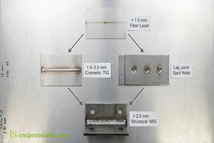
Process selection matrix across sheet gauges—fiber laser (0.5–3.0 mm, the clear winner below 1.5 mm), cosmetic TIG (1.5–3.0 mm), resistance spot welding (lap joints), and structural MIG (>2.0 mm).
How to Optimize Weld Joint Design to Prevent Defects?
The most obvious differences in practical weld joint design for sheet metal are joint fit-up, edge overlap, and self-locating features. Butt joints in thin sheet metal must have root gaps less than 0. 1 mm to avoid burn-through, while corner joints benefit from the use of 50% material overlap (a self-filling feature). Tab-and-slot alignments and staggered stitch welds remove the need for dedicated alignment fixtures, and halve heat input.
Sheet Metal Joint Fit-Up and Gap Tolerance Guidelines
Adherence to exacting root gap tolerance criteria prevents burn-through and collapse in typical weld joint designs:
|
Joint Type |
Material Gauge Range |
Target Root Gap |
Maximum Overlap / Lip |
Recommended Process |
|
Square Butt |
0.8 mm – 2.0 mm |
≤0.1 mm (max 0.2 mm) |
N/A (flush fit-up) |
Fiber Laser / Pulse TIG |
|
Outside Corner |
0.5 mm – 3.0 mm |
≤0.1 mm |
0.5t (half-thickness lip) |
Autogenous Laser / TIG |
|
Lap Joint |
0.6 mm – 3.0 mm |
Zero gap (<0.05 mm) |
3t to 4t minimum overlap |
Resistance Spot / Fillet MIG |
|
Flanged Edge |
0.5 mm – 1.2 mm |
≤0.1 mm |
2t to 3t standing flange |
Melt-down Laser / Micro-TIG |
Core Joint Design Rules for Thin Gauges
Accuracy of fit-up affects structural consistency in any metal welding process:
- Keep square butt gap sizes to be less than 10% of sheet thickness (max 0.2 mm) in order to prevent reducing travel speeds and tripling heat input.
- Use 50% sheet overlap for outside corners (0.5t), so that the extra sheet edge will fuse automatically into corner radius with no use of additional filler wire.
- Increase the overlaps in lap joints to 3-4 times the sheet thickness, thus allowing a heat conduction path that will prevent blow outs during fillet welding.
- Keep the welds at least 3 times the sheet thickness away from the radiuses of bend relief to prevent thermal stress from developing any cracks on the pre-strained bend corners.
- Ensure a distance of 4 times the sheet thickness for through holes and mounting cut-outs from welds in order to prevent any distortion due to heat.
Integration of Self-Fixturing Tabs and Slots
By incorporating self-fixturing capabilities into all flat sheet blanks using high-speed laser cutting, fixture costs and assembly lead times are decreased:
- Male tabs (10mm to 15mm width) that fit into slots with +0.10mm clearance hold your parts at precise 90-degree angles without the use of alignment tools.
- Small relief notches along the long flanges interrupt the continuously welding path that contributes to warping.
- Tapered and wedge profile tabs give positive friction mechanical locking so that a multi-piece chassis can stay rigid before any arc is struck.
- Artificially instating edge standoffs on a structural bracket, creates repeatable gap stops, that will maintain consistent resistance spot welding pitch.
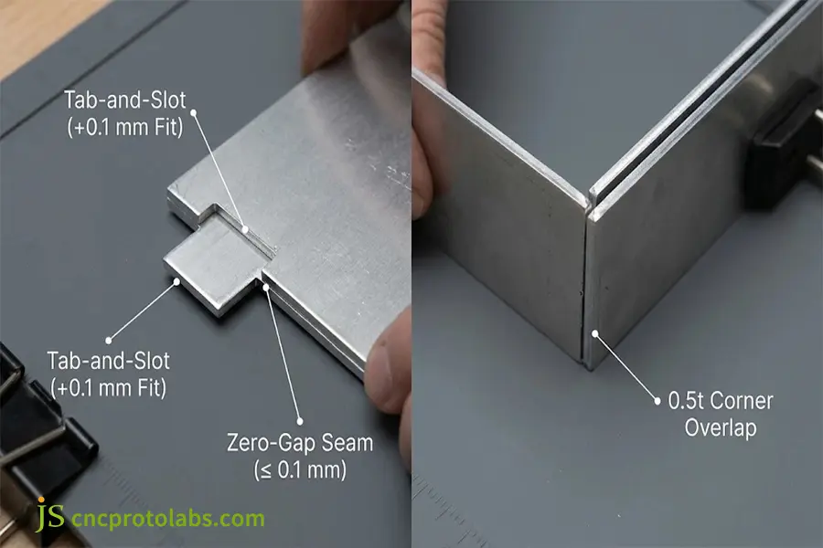
DFM joint configurations featuring +0.1 mm clearance self-locating tabs, zero-gap butt fit-ups, and 0.5t outside corner overlaps to prevent burn-through.
Sizing and Stitch Welding Rules
Specifying oversized welds adds heat without increasing mechanical strength:
- Ensure weld throat sizes are less than 70% of the sheet thickness, and utilise common welding symbols shown on 2D drawings to avoid weld overwelding.
- Change to separated stitch welds (for instance, 20 mm welds at 60 mm intervals) on seams longer than 300 mm to reduce heat input by 65% with the same structural integrity.
- Apply back-step welding procedures, having short 50 mm welds run in a backward direction from previously made welds.
- Reviewing standard weld joint design practices ensures compliance with AWS D9.1 and prevents welding heat distortion during production runs.
Manual vs Automated Metal Welding: How to Choose?
The choice between manual and automatic metal welding is based on production volumes, part complexity, and tolerance consistency. Manual TIG is the best in terms of operator mobility for prototyping and complex bracket work without any upfront cost for tools. Automatic robotic laser and CMT welding are beneficial starting from around 50 to 100 parts and help cut cycle time by up to 70% with reliable accuracy of ±0.05 mm in weld positioning.
Production Volume Crossover Points
Setup costs compared to labor effort dictate the break-even point for automated fabrication units:
Manual vs. Automated Production Volume Comparison
|
Production Volume |
Recommended Approach |
Tooling Investment |
Typical Part Tolerance |
Labor Profile |
|
1 – 10 Pieces (Prototyping) |
Manual TIG / Handheld Laser |
$0 (modular shop clamping) |
±0.4 mm to ±0.8 mm |
High touch time; rapid setup |
|
50 – 250 Pieces (Mid-Batch) |
Handheld Laser with Fixture Track |
$500 – $1,200 (custom nesting plates) |
±0.2 mm to ±0.3 mm |
Low post-weld surface dressing |
|
500+ Pieces (Volume Run) |
6-Axis Robotic Cell (CMT / Laser) |
$2,000 – $5,000 (pneumatic jigs) |
±0.05 mm to ±0.15 mm |
Minimal cycle time; lowest unit cost |
A realistic welding cost breakdown shows that secondary grinding and manual alignment exceed the arc time in normal fabrications.
Repeatability in Serial Production
Manual metal welding changes from drop to drop throughout long production shifts. The fatigue of the welder can change torch angles, arc length, and speed, resulting in irregularities in penetration depth and bead profile. Automated welding units eliminate these human inconsistencies:
- Six-axis articulating robots move along programmed paths within ±0.05 mm with a maximum speed of 2.0 m/min.
- Laser triangulation sensors trace joint paths in real time, compensating for upstream stamping and press brake tolerances.
- Consistent pneumatic hold-downs provide 0. 40. 6 MPa clamping pressure over the entire part, ensuring consistent thermal sink contact between each cycle.
Evaluating Alternative Manufacturing Methods
Welded assemblies should also be weighed against other common metal joining methods and production routes:
- Welded Assemblies vs. CNC Machining: A review of CNC machining trade-offs verifies that laser cutting, bending, and robotic welding reduce material scrap by more than 60 percent versus CNC milling large enclosures from solid blocks.
- Welded vs. Castings: For comparison, welded fabrications are faster than castings because the tooling cost for producing castings is high.
- Automation Decisions: Identifying when investments in fixture tooling are cost effective needs carefully considering the benefits of automatic vs. manual welding.
What Fixturing and Tooling Strategies Prevent Sheet Warping?
Physical part movement control in sheet metal welding uses precision shop tooling proper clamps and backup bars act as line-of-sight energy absorbers in thin-gauge fabrication, as tolerance-keeper and breaker for relatively flat panels and to resist thermal bending forces.
Pneumatic Hold-Down Fixturing
Mechanical toggle clamps apply unequal pressure to the joint, so that thin sheet metal can be lifted when heated. Pneumatic clamping bars apply uniform pressure along the entire seam:
- Continuous contact pressure of 0.4 to 0.5 MPa is exerted on both sides of the weld line using segmented copper fingers.
- Clamp fingers within 4 mm to 6 mm of the seam edge provide resistance to upward buckling during the heating process, without a cage, but allow clear access for the torch nozzle or laser.
- Quick-exhaust pneumatic valves allow for 5 second clamp and release cycle, providing higher throughput for volume runs.
Purge Chambers and Chill Tooling
Materials which react such as stainless steel and titanium oxidize quickly under the full penetration weld joint if they are not kept away from the atmosphere:
- Specific copper backing bars have continuous gas diffusion chambers of 0.5 mm which supply argon directly into the rear root joint.
- Internal water-cooled channels within thick copper chill blocks maintain tooling temperatures to remain below 60 °C when used continuously in automated cycles.
- The magnetic fixture bed which uses modular steel risers enables quick setup for low production chassis without constructing single use frames.
Quick-Change Modular Tooling Beds
The high-mix sheet metal fabrication facility uses grid-based modular subplates to eliminate single-use fixtures:
- Hardened steel tooling beds have precise holes drilled in patterns of either 16mm or 28mm at exactly 50mm centers.
- Locator blocks and spring loaded edges stops CNC machined from aluminum locate themselves accurately within ±0.05mm in under five minutes.
- Toggle clamps with urethane contact pads exert directional pressure against pins to clamp down the formed sheet flanges.
Mitigating Thermal Expansion Binding in Rigid Fixtures
While tight clamping suppresses out-of-plane buckling, excessive constraining of thin sheet metal welding assemblies results in secondary cracking of hot metal when it pulls back against the hardened locator pins. The remedy that production tooling engineers have devised is floating, or compliant, locators on one side of the fixture bed.
The use of spring-loaded linear slides enable the component to expand along its major axis of longitdinal growth during the welding pass, while maintaining the vertical flange in flat contact with the copper heat sink. When the seam cools below 200 C, the pneumatic hold-downs let go, and the assembly completes a natural contraction cycle unencumbered.
How Does Post-Weld Surface Finishing Impact Part Cost?
Weld deposition is only half the fabrication cycle. In thin sheet metal welding assemblies, it often takes more time to grind, blend, passivate, and level the surfaces than to actually weld.
Grinding and Dressing of Beads
Architectural panels, visible electronics housing, and food grade cabinetry need smooth Class A exterior corners:
- Initial grinding using 60 grit zirconium flap discs ensures that any proud beads are ground flush to the substrate without damaging thin adjoining base metals.
- Follow up conditioning using medium grade non-woven surface conditioning discs removes initial grind marks and aligns the grain direction.
- Fiber laser welded external corners negate the grinding step, leaving only a scotch-brite polish prior to painting.
Chemical Passivation and Surface Restorations
Heat from welding extracts chromium from stainless steel, thus forming a heat tained area that is more susceptible to corrosion:
- Chemical pickling pastes used along stainless joints remove the heat taint and iron contaminants in 15-30 minutes.
- Passivation tanks filled with citric or nitric acid restore the thin layer of chromium oxide protection throughout the welded structure.
- Aluminum weld joints are subjected to glass bead blast for cleaning of any spatter marks prior to clear anodizing or powder coat.
Mechanical Stripping and Correction of Flatness
In the case when high thermal stress bypasses the fixturing controls, corrective mechanical stripping restores the warped panels prior to final inspection:
- Hydraulic arbor presses fitted with urethane pads on vee blocks provide controlled counter-bending force directly on the heat-affected areas to relieve the angular distortion.
- Planishing machines use hardened motorized rollers that roll down the proud welds with a load of 0.5 to 1.2 MPa.
- Spot shrinking is carried out with controlled localized spot shrinking using the oxy-acetylene torch heating to 550 °C and immediate compressed air cooling.
Managing the Preparation of Post-Weld Coating on Sheet Metal Panels
Industrial wet and powder coating welded sheet metal assemblies for industrial powder coating applications or decorative wet paint finishing require complete chemical degreasing and mechanical profiling on all welded line joints. Welding flux, anti-spatter solutions, and localized silicone on wipe rags residues reduce powder coating adhesion resulting in blistering and edge peal under typical salt-spray condition testing.
Weldments are processed in five-stage iron phosphate or zirconium conversion wash tunnels before the powder coating process begins. To meet aesthetic enclosure Class A continuous external finishes, technici-ans fill flush-ground spot weld witness marks with a heat-resistant aluminum body filler and then bake and sand the surface smooth to ensure a flawless mirror finish after passing through the oven cycle.
What Are the Quality Standards for Precision Metal Welding?
Precision metal welding on the sheet metal is done to ISO 13920 class B tolerance requirements in linear terms and ISO 5817 level B quality standards in cosmetic and internal welds. The inspections are carried out by surface visual inspection, dye penetrant test (PT) in case of fine cracks in the surface, and coordinate measuring machines (CMM) in case of flatness of the whole frame within ±0.2 mm.
Governing Welding Standards
Welded sheet metal assemblies meet the requirements of an organized international quality standard. For linear and angular dimensions, there is ISO 13920, with precision sheet structures specified at class B (linear variation 1 mm/1,000 mm) and class F (angle tolerance 20 arc minutes). Imperfections are covered by ISO 5817, class B (cleanroom/medical enclosure, surface micro cracks, incomplete penetration of root, or undercut in excess of 10% sheet thickness), with qualification records and welder performance histories adhering to AWS D9.1 (sheet metal) or AWS D17.1 (aerospace fusion).
Essential Non-Destructive Testing (NDT) Methods
NDT checks the joint integrity and waterproof sealing without destroying the finished parts:
- Visual Testing (VT): Conducted at 1,000 Lux to record surface porosity, burn-through, and common welding defects before the batch joining process.
- Liquid Penetrant Testing (PT): Transparent or fluorescent dye remains on seams for 15 min, then a developer is applied to show micro-cracks under natural or UV light.
- Pressure Decay and Helium Testing: Enclosures intended for liquid cooling or battery storage are pressurized to between 0.2 and 0.5 bar, enabling detection of helium leak rates as low as110 mbar·L/s.
- Macro-Etch Metallographic Cut Checks: The metallographic cross sections cut from the sacrificial tabs are etched with an acid for the determination of the actual root penetration and heat affected zones.
Dimensional Verification through CMM Metrology
The general dimensions of the parts must be checked just as if you were worried about the weld. As high heat checks holes out of round and bows mounting surfaces:
- Articulating CMM arm hold hole centers, true square, and flatness at ±0. 2 mm.
- High speed blue light optical scanning creates a full 3D surface point cloud heatmap, comparing the built enclosure directly with its native CAD nominal geometry.
- All dimensional verification is done using the ISO 13920:2023 geometric tolerances.
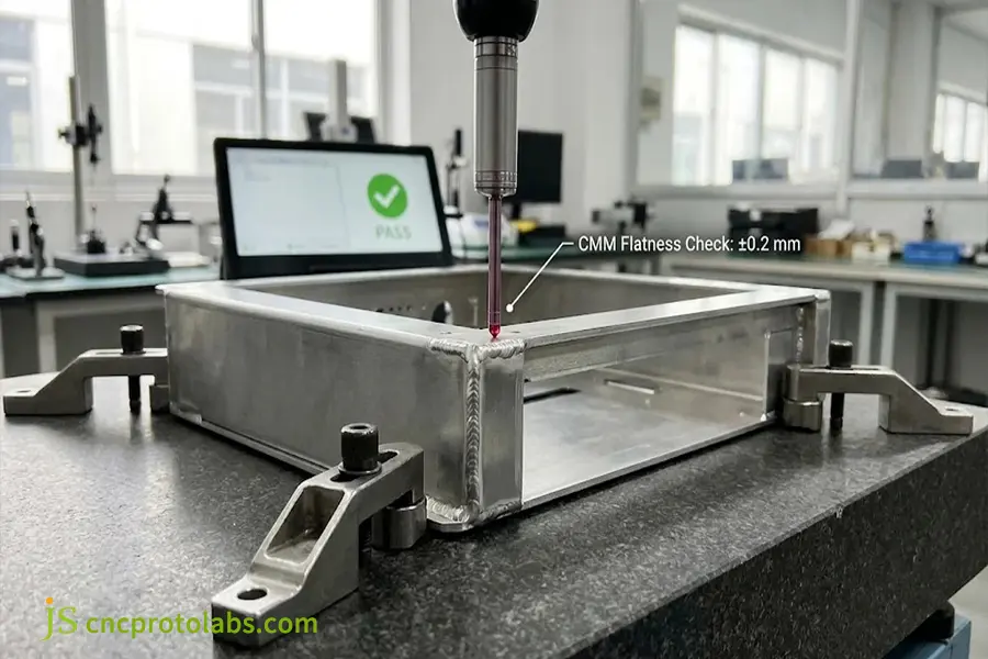
Post-weld CMM dimensional metrology verifying frame squareness and mounting surface flatness within ±0.2 mm.
Process Capability and Welding Procedure Qualification (PQR/WPS)
Systematic process validation is needed before beginning batch production:
- The WPS (Welding Procedure Specifications) contain specific information on travel speed, arc voltage, wire feed rate, and the range of the gas composition, which have been determined using test coupons.
- The PQR (Procedure Qualification Record) proves mechanical conformance through standardized transverse tensile pulls and root bend tests.
- The frequency of testing coupons during production provides SPC data on consistency of weld penetration in multi-station metal welding cells.
How JS Precision Solved Thin Sheet Metal Welding Distortion?
JS Precision solved thermal distortion issues with an aluminum 5052 chassis (gauge 1.2 mm) by replacing conventional manual TIG with fiber laser sheet metal welding together with copper-chill clamping. The amount of heat applied decreased by 58 percent, no burn-through of the base metal occurred, and flatness tolerance on the mounting profile was kept within ±0.15 mm. The secondary welding grinding process decreased by 75 percent and thus the supply of 500 units in two weeks became possible.
Problem: Warping of Thin Medical Enclosures
A manufacturer of medical diagnostics required production of an aluminum electronic chassis, 1.2 mm thick 5052-H32. Their former vendor welded the boxes by manual AC TIG:
- The heat input caused the 450 mm long chassis base to bow upward 1. 8 mm, and thereby began to bind the internal optical scanning rails.
- Cold-straightening the parts on a press brake created stresses in the panels that relaxed out of tolerance weeks later.
- The manual weld bead grinding took 40 min. Per box and it consisted of an inconsistent array of swirl marks underneath the powder coating.
The Solution: Laser Conversion and Copper Chill Fixturing
JS Precision redesigned the production process in three separate phases:
- Fiber Laser Conversion: Changed manual TIG to 1.5 kW fiber laser at 1.4 m/min with 1.2 mm wobble frequency to decrease line energy by 58%.
- Water-Cooled Copper Tooling: Designed and fabricated a pneumatic clamp fixture with copper chill bars in direct contact with the piece in the joint to intercept the maximum heat.
- DFM Tab-and-Slot Blanks: New flat pattern with re-designed self-locating tabs and 0. 6mm offset flanges for the parent metal to fuse without the use of filler wire.
Measurable Production Improvements
The revised process delivered clear, measurable improvements on the shop floor:
- Base flatness increased from 1.8 mm down to 0.12 mm, meeting the customer's requirement of ±0.15 mm without press straightening.
- Grinding time for weld dressing was reduced from 40 minutes to less than 8 minutes, a reduction of 75% per unit.
- Helium leak testing and CMM dimensional scans achieved 99. 4 per cent first-time pass across the 500-piece order.
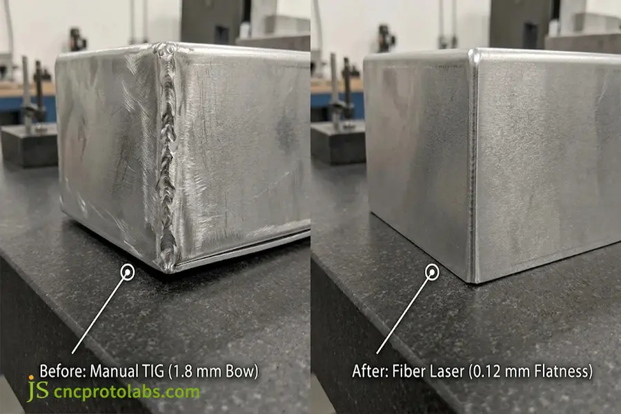
Production comparison on a 1.2 mm aluminum 5052 medical chassis—eliminating a 1.8 mm manual TIG bow down to 0.12 mm flatness via fiber laser welding.
FAQs
Which welding process is best for sheet metal?
The best sheet metal welding process depends on material thickness, production volume, and cosmetic requirements. Fiber laser welding is the best solution for thin sheets from 0.5 to 3.0 mm, giving the lowest heat distortion and travel speeds up to 3.0 m/min. TIG produces the best cosmetic bead for visible stainless panels. MIG is best for structural brackets over 2.0 mm. Resistance spot welding gives the lowest part cost of all for overlapping production stampings.
How thick can you weld sheet metal?
Most sheet metal welding falls within this standard thickness range: materials between 0.5 mm and 6.0 mm. Any thickness below 0.8 mm is welded with micro-TIG or pulsed fiber laser welding to reduce burn-through. Material over 6.0 mm is classified as structural plate manufacturing and is finished with a bevel prep for multi-pass MIG or submerged-arc welding to achieve full root penetration per the specified ISO 9606-1 criteria.
Can you weld different metals together?
Dissimilar metal welding in the context of sheet metal welding involves ensuring the metals have equal melting points and thermal expansion rates. Arc fusion of aluminum and steel is not feasible because it results in brittle intermetallic structures; therefore, clinching and bonding should be used. Nevertheless, successful welding of copper to stainless steel and carbon steel to 304 stainless steel is possible through laser and filler metal usage.
Do you need to stress relieve after welding?
Welded assemblies of thin gauge sheet metal assemblies that are below 2.0 mm do not usually need thermal stress relief, especially when the assembly is made using low heat emitting fiber lasers. But for the case of heavier subframes and enclosures which require CNC milling as a second process, thermal stress relief, involving heating up of the steel to 550 °C to 650 °C, or vibratory stress relief would be required.
How do fabricators stop thin sheet metal from warping?
Prevent sheet metal welding warping through control of heat input and mechanical restraint. Typical techniques are to hold the seam to copper chill bars to conduct heat away, do the stitch welds in staggered rows, use a tab-and-slot sheet configuration with interlocking geometry, and do not overweld. Using automated fiber laser welding is more than 50% less heat input than manual welding torches.
What factors make up sheet metal welding costs?
The total sheet metal welding cost includes materials preparation, setup fixturing, the active arc operation, and secondary grinding. On a manual TIG machine, bead dressing and polishing alone may make up 30% or more of the part cost. Automated robotic cells involve fixture tooling investment ($2,000 to $5,000) but deliver cycle times up to 70% faster, decreasing per-piece costs on batches of 100 or more parts.
How do I get an accurate welding quote online?
To get an accurate sheet metal welding quote quickly, Send 3D CAD (STEP) and 2D drawings showing welding symbols, grade materials, sheet thickness, and linear tolerance of ±0. 2mm. Specifying cosmetic surface details, helium leak testing, and forecast order quantities enable tooling engineers to determine machine cycle times, and provide formal quotations, within 24 hours.
Why choose JS Precision for custom sheet metal welding?
JS Precision maintains a production facility with more than 100 precision machine tools, including integrated automated fiber laser stations, robotic CMT cells, and hand TIG operations. We offer front-end DFM review, build dedicated chill fixtures, and check assembly tolerances to ±0.2mm using CMM metrology. Direct-to-factory conversations eliminate middlemen markups and guarantee quality parts with material certifications.
Conclusion
Precise sheet metal welding balances energy input against the thermal limits of thin metal. Preventing distortion starts at the drawing board: select the right process, design self-locating joints, clamp parts with copper heat sinks, and utilize automated robotic cells when production volumes justify tooling. Following these engineering rules holds tight tolerances, protects surface finishes, and avoids costly post-weld grinding.
When you are ready to request accurate welding quotes, send your 3D CAD drawings to us at JS Precision for a DFM assessment along with a direct quote within 24 hours. Discover more about our sheet metal welding services.
Resource