 English




Welding fabrication service requires quantified tolerance control of joint bevel geometry and fit-up clearance during engineering design to ensure complete joint penetration (CJP) and eliminate lack of fusion, undercut, and excessive thermal distortion. When the base metal thickness is 6.0 mm or greater, the engineering specs require the joints to be beveled either as a Single-V 60° ± 5°, U-groove 15°–20°, root face height to be controlled (1.0mm–2.0mm), and root clearance to be reserved (1.5mm–2.5mm) to allow molten pool access.
Welding Fabrication Service: Core Joint Parameter Reference Matrix
|
Joint Type |
Thickness Range |
Recommended Bevel Angle |
Standard Root Opening |
Root Face |
Quality & Economic Indicators |
|---|---|---|---|---|---|
|
Square Butt |
1.0 mm – 4.0 mm |
0° (no bevel) |
0.8 mm – 1.5 mm |
Full thickness |
Eliminates bevel machining cost, suitable for thin sheet enclosures. |
|
Single-V Butt |
5.0 mm – 16.0 mm |
60° ± 5° |
1.5 mm – 2.5 mm |
1.5 mm ± 0.5 mm |
Ensures full-section penetration, eliminates root lack of fusion. |
|
Double-V/X Butt |
> 16.0 mm |
60° ± 5° (symmetrical both sides) |
2.0 mm – 3.0 mm |
2.0 mm ± 0.5 mm |
Symmetrical welding balances residual stress, reduces angular distortion by 60%. |
|
Bevel T-Joint |
≥ 8.0 mm (vertical plate) |
45° – 50° |
1.0 mm – 2.0 mm |
1.0 mm – 1.5 mm |
Ensures penetration depth and rated shear strength under dynamic loading. |
From the AWS D1.1/D1.1M:2025 standard, a single-V butt joint of 5–16 mm plates should have a 60° ± 5° included angle with 1.5–2.5 mm root opening to get a full joint penetration. Based on ISO 9692-1:2013, groove type and dimensions for fusion welding are dictated by plate thickness and joint geometry, the U-grooves for instance, are at 15–20 bevel angle for plates >16 mm.
Proper design of bevel geometry and assembly clearances are the key physical factors determining welding penetration and the resultant amount of heat generated, reducing post-weld inspection and secondary machining costs by approximately 40%.
Why Must Welding Fabrication Services Follow Strict Joint Bevel and Clearance Rules?
Standardizing joint bevels and fit-up clearances in welding fabrication service balances arc penetration depth with molten pool containment, directly eliminating cold lap, excessive spatter, and severe angular distortion across heavy load-bearing weldments.
Physical constraint mechanism of bevel and root clearance
If the plate thickness is ≥ 6.0 mm, flat-end butt joint welds are not fully capable of penetrating the metal and, because of this, beveling should be done. Arc welding of the root face is not possible if the root spacing is < 1.0 mm, and the consequence is incomplete root fusion; a space of > 3.5 mm destroys the surface tension of the weld puddle and causes burn-through.
Modern precision manufacturing ensures assembly accuracy.
In real-world scenarios of JS Precision dealing with heavy structural component projects, the laser 3D alignment inspection system together with rigid fixtures can limit the variation of assembly root clearances on 3,000 mm workpieces to ≤ 0.3 mm to guarantee that NDT first-pass yield in custom metal welding fabrication service can exceed 98.5%.
Unsure if your weld groove design meets specifications? Get a free DFM assessment now, and our welding engineers will provide optimization suggestions for bevel angles and clearances based on your drawings.
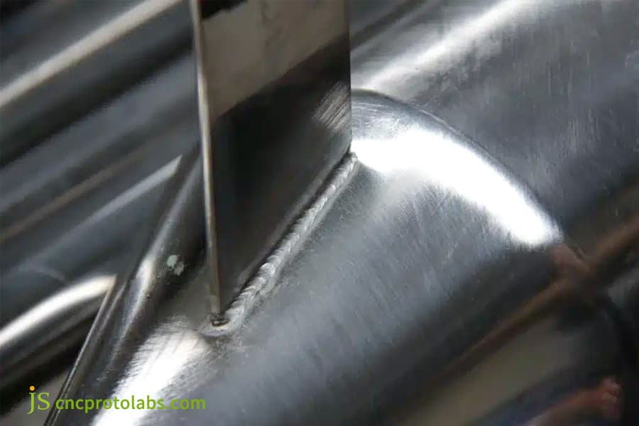
Figure 1: Close-up of welded joint bevel on metal tank.
How to Calculate Weld Bevel Angle and Geometry for Different Plate Thicknesses?
The cross-sectional volume of a weld groove dictates whether an engineer should specify Single-V (60°), Double-V (60°), or U-grooves (15°–20°) in joint bevel design , scaling proportionally with plate thickness to optimize metal deposition and penetration.
Plate thickness grading and bevel geometry selection
JS Precision is an experienced welding company with a vast background in pressure vessel projects. Based on our hands-on experience, when the thickness of the plate is ≤ 4.0 mm, we recommend a Type I flat butt joint (1.0 mm ± 0.2 mm root clearance); for 5.0-16.0 mm thicknesses, we suggest a single V joint (60° ± 5°). Angles < 45° often mean a lack of fusion on the root side, whereas angles > 70° can result in an increase of the amount of deposited metal by more than 35%.
AWS D1.1/D1.1M:2025 states: single V-groove angle 60° ± 5°, root root clearance 1.5-2.5 mm.
For thicknesses > 16.0 mm, a symmetrical double-V or narrow root clearance U-groove (15° bevel with a root fillet radius of 5.0-8.0 mm) should be selected and this welding preparation can save up to around 45% of the welding wire consumption. As a sheet metal welding fabrication service provider, we follow strictly joint bevel design based on this standard.
Comparison of weld metal volume and heat input for different bevel types
|
Plate Thickness (mm) |
Groove Type |
Included Angle (°) |
Root Radius (mm) |
Filler Area per Unit Length (mm²) |
Relative Heat Input Index |
|---|---|---|---|---|---|
|
10.0 |
Single-V |
60 |
— |
18.0 |
1.00 (baseline) |
|
10.0 |
Double-V |
60 (each side) |
— |
12.5 |
0.69 |
|
20.0 |
Single-V |
60 |
— |
58.0 |
1.00 (baseline) |
|
20.0 |
Double-V |
60 (each side) |
— |
37.0 |
0.64 |
|
20.0 |
U-groove |
15 |
6.0 |
28.0 |
0.49 |
|
30.0 |
Single-V |
60 |
— |
125.0 |
1.00 (baseline) |
|
30.0 |
Double-V |
60 (each side) |
— |
78.0 |
0.62 |
|
30.0 |
U-groove |
15 |
8.0 |
52.0 |
0.41 |
According to AWS D1.1/D1.1M:2025, Single-V groove with 60° included angle for 10 mm plate yields approximately 18 mm² filler metal cross-section per unit length. According to ISO 9692-1:2013, U-groove with 15° bevel and 6 mm root radius reduces filler volume by 40% compared to Single-V for plates over 16 mm.
Using U-shaped bevels for the plate thicknesses exceeding 20.0 mm results in more than 50% weld metal area reduction, lowers heat input to a value of 0.41, and at the same time effectively minimizes welding distortion and residual stresses.
How Does Weld Clearance Impact Weld Penetration Depth and Defect Prevention?
Root weld clearance functions as the primary mechanical control for molten pool fluid dynamics at the joint root, determining whether an automated weld achieves complete joint penetration or suffers burn-through.
Assembly clearance tolerance window and defect causes
The allowable clearance tolerance for butt joints in an assembly is 1.5 mm ± 0.5 mm. Clearances less than 0.8 mm usually lead to microcracks in the area of the weld root, which greatly increases the risk of fatigue; clearances more than 3.0 mm cause the molten metal to droop, creating undercuts 0.8 mm deep or more.
Section IX of ASME BPVC (2025 edition) takes dynamic and pressure load-welding joints to be totally free of root-side undercuts. In other words, no root-side undercut is permissible at the root of these welds.
To meet the clearance variation requirements at 3,000mm workpieces, JS Precision has incorporated welding joint design rules with firm fixtures and a laser 3D alignment system that keep variation at a maximum of 0.3 mm.
Engineering implementation of assembly clearance control
Our expertise has shown that in marine structural projects, pneumatic internal support clamps maintain the root opening at 1.8 mm ± 0.2 mm. Alongside pulsed GMAW, it also helps to maintain the size of the root root opening between 0.8 to 1.2 mm continuously, which in turn guarantees quality delivery in structural metal weld manufacturing.
Controlling the fit-up root opening is vital in welding quality. Request our clearances and control solution sheets for measuring to learn how it is possible to consistently manufacture using maintaining an assembly window of 1.5 mm ± 0.5 mm.
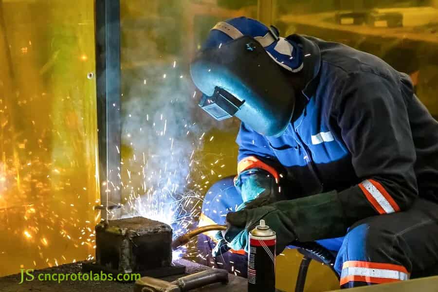
Figure 2: Welder working on metal with sparks and smoke.
Design Rule 1: How to Balance Root Face and Root Clearance to Eliminate Burn-Through?
Preventing arc blowout while ensuring full penetration in weld joint design requires a precise dynamic equilibrium between root face thickness (1.5 mm–2.0 mm) and root clearance (1.5 mm–2.0 mm) across structural butt joints.
The inverse complementary relationship between root face and root opening
The root face supports the fusion pool and prevents breakdown at the root. The root opening allows the deposited metal to reach the back side of the joint. The two are inversely proportional and complementary.
- At 0 mm root face level, a root pass current of 80–100 A can be melted away within 0.5 s and burnt through.
- Whereas, if the root face is greater than 3.0 mm, then a traditional arc can hardly melt the center of the root face. So, the root cold weld does not fuse completely mating clearance.
Root face 1.5 mm ± 0.3 mm and 2.0 mm ± 0.5 mm recommended DFM combination for engineering; Grooving can be carried out on a CNC machine that will ensure a batch root face consistency of ±0.1 mm and will save the process of manual grinding.
Engineering verification of root face root opening matching
After several boiler header projects handled by JS Precision, we have found that if root face is 1.5 mm and the root opening is 2.0 mm, then RT will reveal 100% root weld fusion complying with ASME criteria. This plan will be incorporated into WPS as a standard practice for welding joint design rules and promoted to custom welded assembly supplier projects.
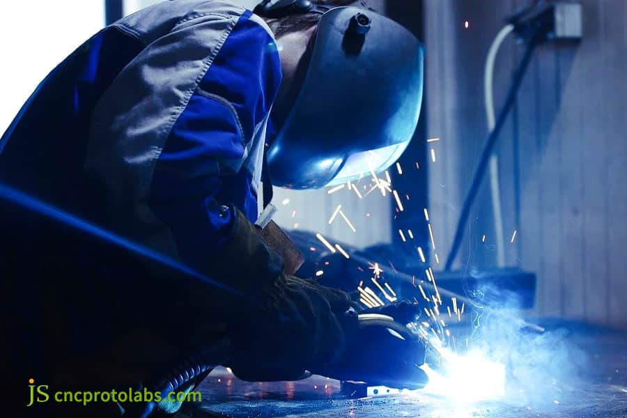
Figure 3: Welder performing precision welding on metal part.
Design Rules 2-5: How to Optimize Torch Access, Asymmetry, and Material Shrinkage?
Comprehensive structural weldability analysis within a precision welding service involves validating four physical constraints during the CAD phase: torch accessibility envelopes, joint alignment offsets, symmetrical weld sequencing, and material shrinkage allowances.
Rule 2: Physical accessibility and spatial envelope of welding torch
The minimum tilt angle of the nozzle at either side of the weld should be ≥ 45°, and a free space cylinder of ≥ 120 mm radius has to be provided around the axis of the weld to avoid contact that creates turbulence of the shielding gas. JS Precision used 3D simulation to confirm accessibility as part of welding DFM service.
Rule 3: Assembly Misalignment Must Be Under Tight Control
The amount of misalignment is expressed as both the percentage of the thickness of the thinner plate (up to 10%), and as an absolute value (maximum 1.5 mm) to prevent stress concentration.
Rule 4: Double-Sided Balanced/Asymmetrical Bevels to Offset Residual Stress
Thick-walled box girders are manufactured by an asymmetrical double V bevel (60% from the face side and 40% from the back side) which, combined with welding sequence, reduces post-weld straightening work by 70%.
Rule 5: Design root clearances with allowance for material thermal expansion
316 L stainless steel shows a thermal expansion coefficient of 16.5 × 10⁻⁶/K, which is 40% greater than carbon steel. Assembly root clearances should be opened by 0.5 mm, and tack welds should be placed every 100-150 mm. We strictly follow these rules in precision metal welding contract manufacturing to guarantee assembly accuracy.
Need a complete welding DFM checklist? Contact our engineers for a standardized verification template that includes torch accessibility, misalignment, symmetrical bevels, and thermal expansion compensation.

Figure 4: Welder using torch on metal frame with sparks.
Case Study: How JS Precision Solved Porosity and Warpage in Medical 316L Stainless Steel Frames?
For a European medical vacuum chamber project, JS Precision engineered an optimized robotic GTAW(TIG) bevel and fixture clearance strategy on 10.0 mm thick 316L stainless steel, resolving helium leak failures and angular distortion.
Difficulties encountered by customers
The first design of the stainless steel 316L vacuum chamber frame (1200×800×600 mm, wall thickness 10.0 mm) made for a European medical equipment project was a single V bevel of 45° with a zero clearance. But, only 64% of the chambers passed the helium leak test with the helium mass spectrometry method. The twisting deformation was a maximum of 4.5 mm and the surface was insufficient to achieve the required seal for CNC precision machining.
JS Precision Solution
- Weld preparation redesign: Redesigned bevel for DFM changed to 55° asymmetric double V bevel with 1.5 mm ± 0.1 mm root face, finished by CNC milling and with roughness Ra 3.2 μm.
- Water-cooled copper liner clamp: pneumatic internal support fixing root clearance 1.8 mm ± 0.2 mm, 99.999% pure argon is fed at 12 L/min on the back side to maintain backing pressure.
- Low thermal input pulse GTAW: the base value is 60 A, peak value is 160 A, the frequency is 2.5 Hz, and jump welding with symmetry.
Lessons learned from failure
The first simple spot welding for 316L weld metal induced thermal stress led to root clearance shrinkage below 0.4 mm and failed penetration. The solving method was changed to laser spot welding with mechanical limit pin through hole. In custom precision welding fabrication projects, root clearance control is strict for helium weld test inspection. The stainless steel welding service quotation was fully accounting for beveling, time and NDT ratio.
Final result
- Helium leak detection rate ≤ 1.0×10⁻⁹ Pa·m³/s, 100% first pass rate.
- The torsional deformation was reduced to ≤ 0.6 mm.
- The finishing allowance for the sealing surface is 0.5 mm ± 0.1 mm.
- The scrap rate and straightening time were reduced by 32%.
According to AWS D1.1/D1.1M:2025 (Structural Welding Code — Steel) and JS Precision quality engineering records (Report No. JS-QA-2025-MED07).
Need to optimize the bevel design of your welded structural components or solve deformation problems? Send your CAD model and engineering drawings to us now, and our engineering team will provide a DFM assessment and quotation within 24 hours.
What Are the Quality Inspection Standards and NDT Acceptance Limits for Precision Welding?
Weld seam integrity for critical fabrications under a precision welding service is benchmarked against ISO 5817 Level B and AWS D1.1 criteria, deploying calibrated Non-Destructive Testing (NDT) to verify surface and volumetric defect compliance.
Comparison Table of Welding Quality Acceptance Standards and Defect Limits
|
Defect Type |
ISO 5817 Level B Limit |
ISO 5817 Level D Limit |
AWS D1.1 Limit |
Recommended NDT Method |
|---|---|---|---|---|
|
Cracks |
Zero tolerance |
Zero tolerance |
Zero tolerance |
VT + PT/MT |
|
Lack of Penetration |
Zero tolerance |
≤ 0.5 mm depth |
≤ 0.25 mm depth |
UT/RT |
|
Undercut Depth |
≤ 0.5 mm |
≤ 1.0 mm |
≤ 0.8 mm |
VT |
|
Porosity Size |
≤ 1.0 mm dia. |
≤ 2.0 mm dia. |
≤ 1.5 mm dia. |
RT/UT |
According to ISO 5817:2023 (Fusion-Welded Joints in Steel, Nickel, Titanium and Their Alloys — Quality Levels) and AWS D1.1/D1.1M:2025 (Structural Welding Code — Steel).
NDT Acceptance Standards and Process Source Control
To achieve ISO 5817 Level B conformity, bevel matching for angle and root clearance has to be exact when planning the welding work, as defects should be prevented at the source. JS Precision, as a certified metal welding fabrication factory, uses this standard as an internal acceptance benchmark in welding DFM service to ensure a first-time NDT pass rate of over 98.5%.
How to Choose a Custom Welding Fabrication Manufacturer with End-to-End DFM Capabilities?
Evaluating custom contract manufacturers for an end-to-end welding fabrication service requires reviewing four core technical capabilities: in-house CNC bevel machining accuracy, certified WPS documentation, robotic welding precision, and full-spectrum NDT inspection.
The procurement and engineering team needs to verify the integrity of the process chain and quality management system:
- International welding procedure qualification: ASME Sec IX, ISO 9606-1, EN 1090-2 certified.
- Beveling equipment: five-axis laser beveling machine and CNC gantry milling machine, assembly beveling tolerance ±0.2 mm.
- Automated welding and inspection: Robotic Welding Systems and Full-Spectrum NDT (VT/PT/MT/UT/RT).
- Post-weld heat treatment and finishing: stress-relief annealing furnace and coordinate measuring machine (CMM).
To submit a welding fabrication RFQ, please prepare a 3D model and 2D drawings with weld symbols. JS Precision, being a custom metal welding supplier, will deliver a DFM report which includes bevel design and cost estimates within 24 hours.
FAQs
Q1: Why is beveling required for plate thickness over 6 mm?
Flat butt joining for thicker-than-6mm plates cannot result in a fully penetrated joint. The physical space given in 60° bevels allows electric arc movement and heat input can come to the root which is also capable of softening the root face without leaving any underpenetrated areas.
Q2: How can excessive fit-up clearance be corrected during fabrication?
If the joint root opening is more than 3 mm, direct filler wire welding is not allowed. The bevel edge on one side should be coated with a transition layer first, then the root is to be ground 1.5–2.0 mm, and the root pass is to be applied without fear of burn-through and angular deformation.
Q3: What is the difference between V-groove and U-groove joints in cost and quality?
Machining of V-groove is quite affordable, but the filler requirement for thick plates is quite high and it is also very susceptible to thermal deformation; U-groove requires specially designed milling cutters, so the set-up cost is quite high; but, it reduces weld metal volume by more than 40% and is ideal for high-reliability parts > 16 mm.
Q4: How does JS Precision ensure dimensional tolerances on welded frames?
JS Precision uses a closed-loop that includes laser blanking, CNC beveling, rigid fixture positioning, pulsed low-heat input welding, stress-relief annealing and CNC secondary finishing as a means to keep the frame tolerance within ±0.05 mm.
Q5: What primary factors determine welding fabrication service quotations?
Quotations include the type of base material (carbon steel / stainless steel (316L) / aluminum alloys (5052, 6061, 7075), edge deviation, welding method (hand/robot), the NDT testing ratio (full PT/UT/RT), and machining after welding.
Q6: Why does stainless steel require tighter clearance control and backing gas?
The coefficient of thermal expansion for austenitic stainless steel is 40% higher than for carbon steel. It absorbs heat poorly and is more likely to experience shrinkage and distortion when welded. When exposed to air, the high-temperature molten pool gets easily oxidized. So, the root opening should be tightly controlled at 1.5–2.0 mm, and it is advisable to flow the high-purity argon gas on the backing side to avoid oxidation.
Q7: What is the Heat Affected Zone (HAZ) and how does bevel design reduce it?
HAZ is the weakened area beside the weld due to the heat that cycles through. Using narrow-root opening bevels and blunt-edge designs reduce weld layers, heat input, and the size of the HAZ by over 30% without losing the base material's strength.
Q8: How can engineers submit RFQ drawings for custom welding fabrication?
Send us a 3D model (STEP/IGES) and 2D drawings (PDF/DWG) with weld symbols, bevel angles, tolerances, and NDT grades. Give material standards and delivery dates. Get tiered quotations and a DFM report within 24 hours.
Summary
The engineering design of weld joints' bevels and root openings is a fundamental prerequisite for assessing the mechanical and dimensional stability of load-bearing structural parts, pressure vessels, and frames of precision devices. If one carefully follows Design for Manufacturing (DFM) methods - plate thickness calculations, inverse complementary ratios between root face and root opening, flame accessibility verification, and thermal expansion compensation - engineers and manufacturing engineers can substantially reduce defects such as incomplete penetration and undercut and excessive angular distortion from the manufacturing process at all so the amount of rework will be cut and the manufacturing costs reduced.
If you want to check if your welded structural component is manufacturable or get a custom production solution, send your CAD drawings and technical requirements to our JS Precision engineering channel. The engineering team will analyze your drawings within 24 hours and send you a DFM report with suggestions to alter weld bevels, dimensional tolerance schemes, and estimates of manufacturing costs.

Disclaimer
The contents of this page are for informational purposes only. For JS Precision Services, there are no representations or warranties, express or implied, as to the accuracy, completeness, or validity of the information. It is the buyer's responsibility to identify specific technical requirements and request a formal parts quotation. Please contact us for more information.
Resource

