English



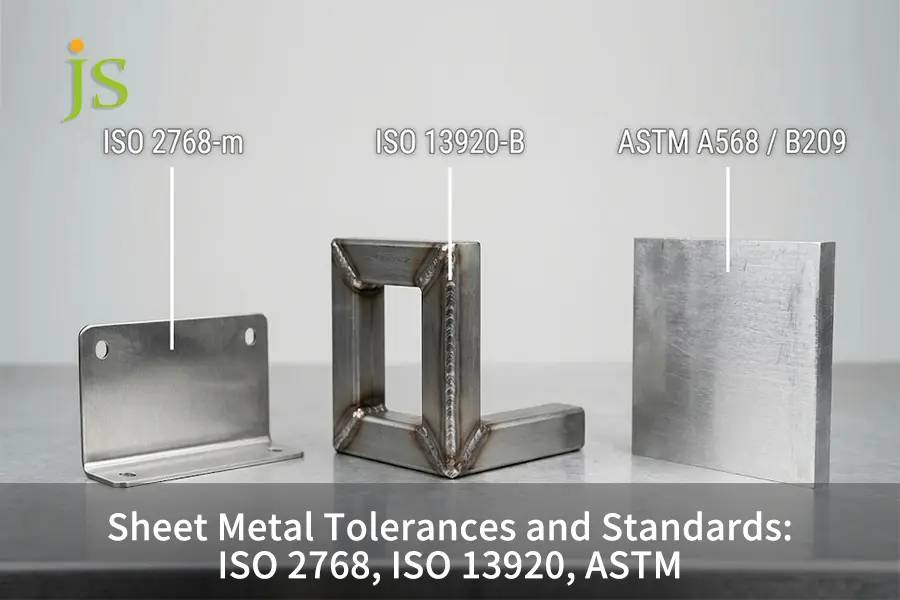

Standard sheet metal tolerances range from ±0.1 mm to ±0.5 mm in laser cutting and forming, based on three separate specifications:
- ISO 2768-1: Covers general linear and angular tolerances for 2D laser-cut and punched features, where Class m is the shop basic specification.
- ISO 13920: Covers welded sheet metal assemblies, taking into account weld shrinkage and heat warping which cannot be handled with general cut tolerances.
- ASTM A568 / B209: Covers steel and aluminum mill stock thickness, controlling gauge tolerances which directly impact press brake bend deductions.
Tolerance restrictions define the ultimate quality boundaries for sheet metal fabrication. Applying one broad callout such as the ISO 2768-1 standard to the whole drawing results in assembly fit-up failures and increased unit quotes, as flat-pattern limits ignore press-brake springback, weld shrinkage and variations in raw coil gauge.
Quick-Reference Overview of Sheet Metal Tolerance Standards
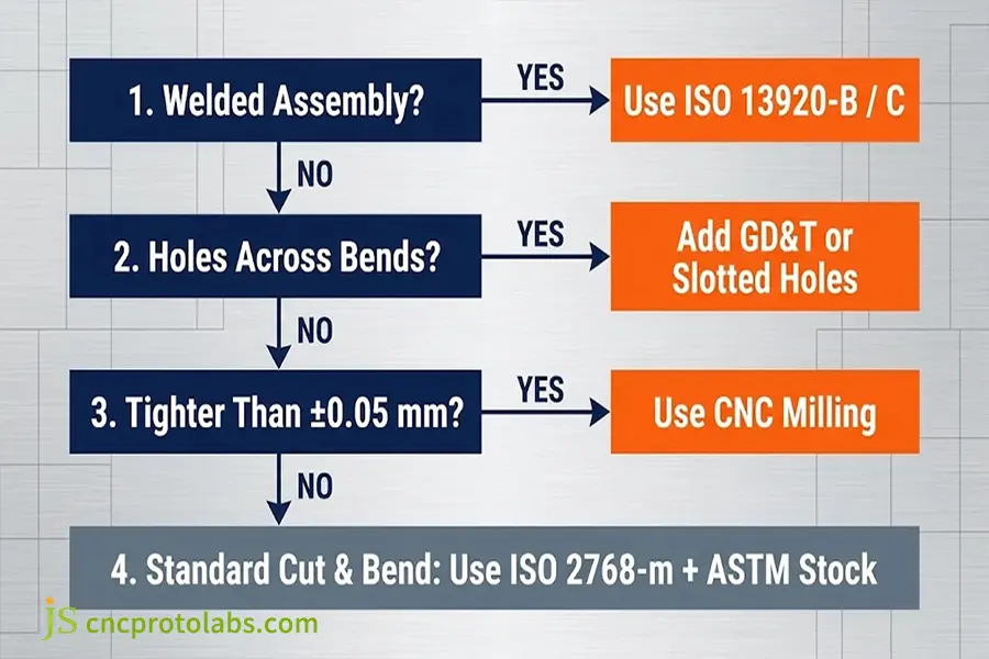
Set tolerances for each manufacturing step. For 2D cut and simple bent features ISO 2768-m. For welded frames ISO 13920 B or C. For raw sheet thickness tolerance ASTM A568/B209. And apply only GD&T tolerance for critical mounting holes around bends.
| Standard / Specification | Governed Features | Common Grade | Typical Linear Tolerance (30-120 mm) | Primary Blind Spot / Failure Risk |
| ISO 2768-1 | 2D laser-cut and punched profiles | Class m (Medium) | ±0.30 mm | Does not control press-brake springback or weld shrinkage |
| ISO 13920 | Welded sheet metal frames and housings | Class B / C | ±2.0 mm to ±4.0 mm | Excludes weld bead surface defects (covered by ISO 5817) |
| ASTM A568 / B209 | Raw steel, stainless, and aluminum stock | Standard Mill | ±0.08 mm to ±0.15 mm (2 mm sheet) | Gauge numbers are nominal, and thickness varies across coils |
| Explicit GD&T Callouts | Critical mounting holes across bend lines | Custom Print | ±0.05 mm to ±0.10 mm | Applying across non-functional flanges doubles unit cost |
What Do ISO 2768 General Tolerances Control in Sheet Metal?
The ISO 2768 general tolerances are to be used on linear, angular, and basic geometry dimensions that are not individually called out in sheet metal components, with the ISO 2768-m being the shop basis (tolerance of ±0.1 mm for small features, ±0.3 mm for medium-sized dimensions, and ±1° for short bends). ISO 2768-1 covers only 2D laser cut or punched components that are limited to just one plane as pressing deforms the metal grain.
Breaking Down ISO 2768-1 Linear and Angular Classes
ISO 2768-1 defines four classes of linear and angular tolerances: f (fine), m (medium), c (coarse), and v (very coarse).
- Class m (Medium): The universal baseline for worldwide sheet metal shops.
- Class f (Fine): For tight 2D laser cut contours on thin stock or secondary machined features.
- Class c (Coarse) & v (Very Coarse): For thick plate operations, class v is not common in CNC fabrication.
|
Nominal Length Range (mm) |
Class f (Fine) |
Class m (Medium) |
Class c (Coarse) |
Class v (Very Coarse) |
|
0.5 to 3 |
±0.05 mm |
±0.10 mm |
±0.20 mm |
N/A |
|
Over 3 to 6 |
±0.05 mm |
±0.10 mm |
±0.30 mm |
±0.50 mm |
|
Over 6 to 30 |
±0.10 mm |
±0.20 mm |
±0.50 mm |
±1.00 mm |
|
Over 30 to 120 |
±0.15 mm |
±0.30 mm |
±0.80 mm |
±1.50 mm |
|
Over 120 to 400 |
±0.20 mm |
±0.50 mm |
±1.20 mm |
±2.50 mm |
|
Over 400 to 1,000 |
±0.30 mm |
±0.80 mm |
±2.00 mm |
±4.00 mm |
|
Over 1,000 to 2,000 |
±0.50 mm |
±1.20 mm |
±3.00 mm |
±6.00 mm |
Why ISO 2768-2 Is Outdated in Today's Drawings
Older CAD drawings often show ISO 2768-mK or ISO 2768-mH in the title block.
- Standard Withdrawal: ISO 2768-2 (general flatness, straightness, and perpendicularity tolerance values for classes H, K, and L) was officially withdrawn in 2019 and superseded by ISO 22081.
- Inspection Disputes: Specification of ISO 2768-2 in new drawings leads to disputes in inspection of thin panels that inherently bend from laser-cutting process.
- Current Practice: Use ISO 2768-m for linear tolerances and use GD&T frames with datums when required only for flatness and squareness of the assemblies.
The Physics Behind Bend Line Tolerance Stack-Up
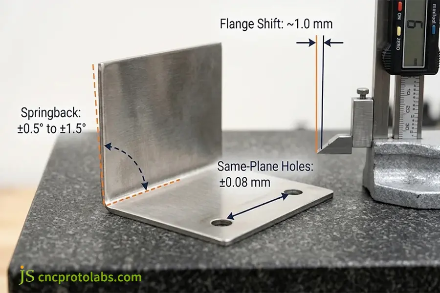
Application of ISO 2768-m across the bend line results in constant print errors. In air bending, the punch presses the sheet into a V-die. Variations in coil-to-coil tensile strength cause the metal to springback once the punch clears. ±0.5° to ±1.5° of springback shift across a long flange results in the flange tip being displaced by almost 1.0 mm, outside ISO 2768-m limits. Tighter control requires setups detailed in bending tolerances for formed parts.
What Laser Cutting Tolerances and Bend Limits Can Sheet Metal Hold?
Modern fiber laser cutting tolerances hold ±0.05 mm to ±0.10 mm on flat sheet metal profiles, while the tolerance range for CNC turret punching is the same as that of the tool used and the tolerance for air bending ranges from ±0.25 mm to ±0.50 mm on each bend. The reason behind the variation in tolerance is the difference between 2D and 3D processing techniques.
Shop-Floor Capability Benchmarks by Process
Compare print requirements with actual machine capabilities as listed in the FMA Precision Sheet Metal Tolerance Guidelines (Fabricators & Manufacturers Association, 2024):
- Fiber Laser Cutting: Maintains tolerances from ±0.05 mm to ±0.10 mm on 2D shapes. Ensure that cut holes' diameters are not less than the material thickness to avoid melting from the heat-affected zone (HAZ). Read here to learn about laser vs waterjet cut quality and tolerances on thicker plates.
- CNC Turret Punching: Punch hole diameters have tolerances of ±0.08 mm when tool steel punches are used. Keep holes clear of bend lines to avoid hole stretching during forming, covered in hole diameter and edge distance precision.
- CNC Press-Brake Air Bending: Tolerances of ±0.25 mm for single bend flanges and ±0.5° on bend angles (±0.3° with laser angle sensors). Stack up increases with number of bends.
Why Sheet Metal Cannot Match CNC Machining Precision
Cold-rolled sheet metal holds locked-in rolling stresses.
- Stress Release Distortion: Stress is released through cutting outer profiles or bending along a radius, resulting in twisting or bowing of panel.
- Rigid Billet Advantage: CNC milling uses rigid spindles to cut stress-relieved solid billets with tolerances from ±0.01 mm to ±0.05 mm.
- Precision-Cost Ratio: Sheet metal achieves lightweight enclosure construction at a lesser cost through reduced 3D rigidity for increased forming speed.
ISO 2768 vs ISO 13920: Which Sheet Metal Tolerance Chart Applies?
An ISO 2768 vs ISO 13920 Comparison reveals that ISO 2768 deals with each laser cut or bent component before assembly while ISO 13920 is for welded structures where the weld heat results in shrinkage and distortion of the welded frame. A sheet metal tolerance chart proves that ISO 2768-m cannot be used on a welded frame since TIG/MIG weld will result in shrinkage by several millimeters.
ISO 13920 Classes for Welded Structures
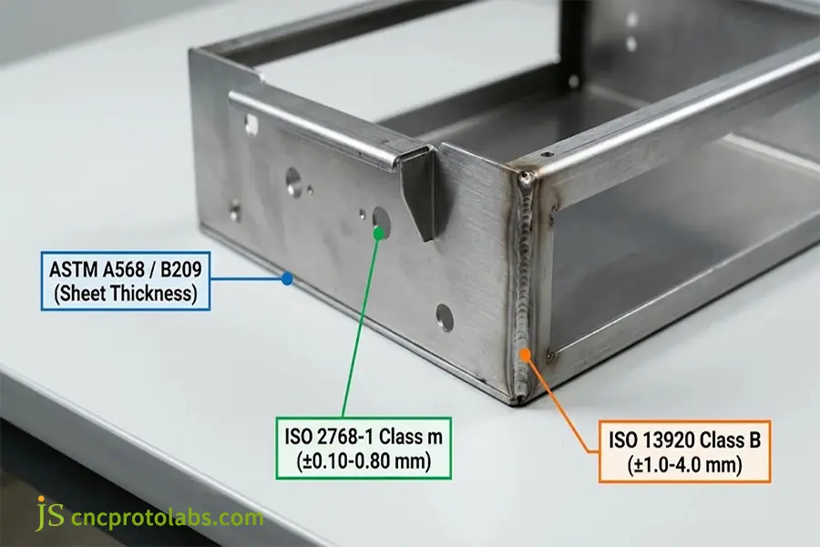
ISO 13920 categorizes general tolerances for welded assemblies into four linear tolerance classes (A, B, C and D) and four flatness or straightness tolerance classes (E, F, G and H).
- Shop Baseline: ISO 13920-B (also ISO 13920-BF, incorporating linear category B with flatness category F) applies to factory cabinets, frames, and battery boxes.
- Tolerance Limits: The most precise welded assembly category is class A (with a tolerance of about ±2 mm on 1-meter weldments), whereas categories B and C increase to account for greater thermal input from the weld.
- Weld Quality Exclusion: ISO 13920 addresses size of the assembly alone, whereas ISO 5817 includes weld appearance and porosity.
How ASTM A568 and ASTM B209 Govern Raw Stock Thickness
Neither ISO 2768 nor ISO 13920 regulate the thickness of incoming raw sheet material. Instead, mill thickness is specified by ASTM standards:
- ASTM A568 / A568M: Covers hot-rolled and cold-rolled carbon, structural, and high-strength low-alloy (HSLA) steel sheets. (ASTM A240 covers stainless steel sheet).
- ASTM B209: This covers the aluminum and aluminum-alloy sheet and plate, thickness tolerances.
- Gauge Variation Impact: Nominal 16 Gauge steel (1.52 mm) varies about ±0.10 mm through a coil based on ASTM A568. Air bend form changes in thickness alters the neutral axis and flange lengths unless the K-factor is changed.
Comprehensive Sheet Metal Tolerance Chart & Cross-Process Matrix
| Comparison Dimension | ISO 2768-1 (Class m) | ISO 13920 (Class B) | ASTM A568 / B209 | Alternative: CNC Milling |
| Tolerance Range | ±0.10 mm to ±0.80 mm | ±2.0 mm to ±4.0 mm (up to 1000 mm) | ±0.08 mm to ±0.15 mm (stock thickness) | ±0.01 mm to ±0.05 mm |
| Core Process | 2D laser cutting, punching, single bends | TIG/MIG welding, spot welding, jigs | Rolling mill coil production & QC | 3-axis/5-axis milling on solid/datum pads |
| Cost & Lead Time | 1.0× Baseline (Standard CNC setup) | 1.3× to 1.6× (Welding fixtures required) | Material Base (+15%-25% for half-mill) | 3.5× to 6.0× (High chip-removal time) |
| Primary Fail Mode | Applied to welded parts, fails due to weld shrinkage | Applied to precision bores, causes bolt interference | Unchecked gauge drift shifts bend K-factors | Used on large thin enclosures, causes chatter |
For plain cut and simple bend components, adopt ISO 2768-m tolerance grade, use ISO 13920-B/C when the process involves welding, ensure that coil tolerance is within the limits specified by ASTM A568/B209, and utilize hybrid "welding followed by CNC machining" when tolerances are stricter than ±0.05 mm.
How Do You Specify Sheet Metal Tolerances Under ASTM and ISO?
Avoiding problems with the fit-up during assembly requires setting sheet metal tolerances through a three-level drawing approach: refer to ASTM A568 or B209 for the gauge of raw stock, use ISO 2768-m in the title block for cutting and bending, use ISO 13920-B for weldments, and use GD&T true position (±0.05 mm to ±0.10 mm) only on mounting holes on a datum plane.
4 Useful DFM Guidelines for Print Callouts
- Enforce Single-Plane Datum Dimensioning: Make sure critical mounting holes are dimensioned from a datum edge that lies in the same plane to retain accuracy of the laser.
- Use Slotted Holes for Tolerance Stack Up: Instead of using conventional clearance holes on one mating panel, use slotted holes wherever there are fasteners going through a bend or weld joint; this allows some play to accommodate stack up.
- Specify Your 2D Drawing with Consistent Title Block Notes:
MATERIAL: 304 STAINLESS STEEL ACCORDING TO ASTM A240, NOMINAL THICKNESS 2.0 MM. UNLESS OTHERWISE STATED: LINEAR AND ANGULAR TOLERANCES ACCORDING TO ISO 2768-m. WELDED ASSEMBLIES ACCORDING TO ISO 13920-B. WELDING QUALITY ACCORDING TO ISO 5817-C. REMOVE ALL BURRS AND BREAK ALL SHARP EDGES UP TO 0.2 MM.
- Add Proper Bend Reliefs at Corner Intersections: Add rectangular or obround bend reliefs deep enough to remove material thickness and inner bend radius, preventing corner tearing and sheet metal bending defects and drawing accuracy failures.
Case Study: Reduction of 38% Interference at Assembly on a 304 Stainless Steel Box
A manufacturer of automated equipment ordered 300 pieces of an outdoor control enclosure of size 600 × 400 × 250 mm with 304 stainless steel of thickness 2.0 mm (ASTM A240). The original drawing had ISO 2768-f tolerance through the title block and door hinges' holes on two 90° bends from the back wall.
The first article inspection identified two problems:
- Stack-Up Interference: The incoming coils were not consistent in their thicknesses according to ASTM guidelines, along with the press brake springback on two bends, resulting in an interference of 1.1 mm in the hinge holes and creating binding doors in 38% of the doors.
- Cost Inflation: Using Class f on the large welds caused price quotes to increase by 55%.
During the DFM Review process, JS Precision engineers made three changes to the prints:
- Relaxed tolerances for cut-and-bend operations to ISO 2768-m while assigning ISO 13920-B for seam-welded shell.
- Referenced hinge hole pattern to a new datum point at the front flange while replacing holes on mating chassis with slots.
- Thickness of incoming coil was measured, and K-factor of the press brake was set at 0.42.
The door-to-frame assembly problems decreased from 38% to 0%, the scrap rate remained below 0.8%, and the unit cost reduced by 32%. Early print optimization is critical when choosing a precision sheet metal fabrication manufacturer.
What Are the Most Common Questions About Sheet Metal Tolerances?
What is the standard tolerance for sheet metal fabrication if none is specified?
In the absence of any specific tolerances, manufacturing shops assume that ISO 2768-m tolerance applies to cut and bent items while ISO 13920-B applies to welded structures. If ISO 2768-m applies, then the mid-range tolerance level applies between ±0.1 mm to ±0.5 mm to linear features. Depending on defaults, alignment problems can arise with multi-bend parts.
Is ISO 2768 still valid for modern sheet metal engineering drawings?
ISO 2768-1, which refers to linear/angular tolerances, is still valid but ISO 2768-2, which is flatness/squareness, was withdrawn in 2019 and superseded by ISO 22081.
Can laser cutting hold ±0.05 mm tolerances across an entire sheet metal part?
Fiber laser can hold at ±0.05 mm to ±0.10 mm on 2D hole diameters and edges at one flat plane on thin sheet. Cannot hold at 0.05 mm at formed flanges or welds on weld shrinkage and press-brake springback where secondary CNC milling is required.
How do ASTM A568 and ASTM B209 affect sheet metal bend tolerances?
ASTM A568 (steel) and ASTM B209 (aluminum) limits are for raw mill sheet thickness not shop fabrication. Nominal 2.0 mm thick steel can differ by about ±0.10 mm across the width of a coil, changing the neutral axis when air bending and changing flange lengths if K-factors are not compensated.
How much do tighter tolerances increase sheet metal fabrication costs?
Tightening tolerances from ISO 2768-m to ISO 2768-f adds 25% to 55% to the price per piece, mechanical tolerances (±0.05 mm) can double or even triple quotes. Tighter tolerances require slower laser speeds, dedicated tooling, welding fixtures, and 100% CMM inspection.
When should I choose CNC machining instead of sheet metal fabrication for tight tolerances?
Choose CNC machining when parts require linear tolerances tighter than ±0.05 mm, strict flatness across large surfaces, or variable 3D wall thickness. Sheet metal suits lightweight enclosures at low cost, while CNC milling eliminates springback and gauge drift to hold ±0.01 mm to ±0.05 mm.
Conclusion
Correct selection of sheet metal tolerances will consist in assigning the appropriate standards depending on the process stages. It is advisable to use ISO 2768-m for 2D laser cut and simple bends, change to ISO 13920-B or C for welding assemblies, add in mill thickness tolerances according to ASTM A568 or B209, and apply detailed GD&T only for mount interfaces. For material and finishing options across the full workflow, review our sheet metal fabrication guide.
Ready to ensure tolerances on a multi-bend enclosure or welded frame? Submit your STEP/DXF files and 2D drawings, and a JS Precision engineer will run a free DFM tolerance review before production.