English



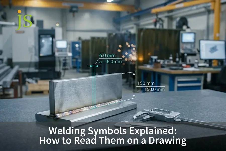

Reading welding symbols on drawings involves understanding a unique system of symbols based on AWS and ISO standards. This system directs the shop welders in terms of location, method, and size of the weld joint on metal.
A complete welding symbol consists of a reference line, an arrow indicating the seam, basic geometric icons, dimensions, and an optional tail.
Blueprint interpretation relies on one main rule: Symbols placed below the reference line specify welds on the arrow side, while symbols above the line indicate welds on the opposite side.
Blueprint Welding Symbols at a Glance
Welding side is determined by the vertical positioning from the reference line, whereas flanking numbers control cross-sectional dimensions and spacing.
|
Element / Position |
Blueprint Location Meaning |
Technical Parameter / Instruction |
Shop Floor Execution Focus |
|
Below Reference Line |
Arrow side of the joint |
Leg size z or groove depth S (left of symbol) |
Deposit weld metal on the exact surface touched by the arrow tip |
|
Above Reference Line |
Other side of the joint |
Weld length L and pitch spacing P (right of symbol) |
Apply weld to the opposite plate face; verify back penetration |
|
Arrow Junction |
Supplementary job markers |
Black flag (field weld) or circle (weld all-around) |
Separate shop fabrication steps from on-site structural erection |
|
Reference Tail |
Process and test codes |
Welding processes (e.g., GTAW, GMAW) and NDT standards |
Match filler wire grades and run specified testing protocols |
What Are the Core Anatomy and Key Elements of Welding Symbols on Drawings?
A standard welding symbol on drawings consists of five foundational elements: a horizontal reference line, an arrow, welding geometry symbols, dimensions, and a tail, if necessary. The reference line provides a place of attachment for all directions, which are always read from left to right. The arrow provides the physical orientation of the joint, whereas its vertical position tells the side of deposition.
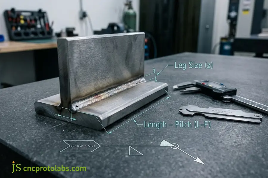
The Reference Line and Arrow Line
Contains all geometry symbols, notes for dimensioning and finishing of shapes. Some of the general drawing and layout rules are:
- Horizontal Orientation: Regardless of the direction of the arrow line, the reference line should be on a level plane with the printing.
- Reading Direction: All dimensional measurements are read in order in this direction from left to right.
- Arrow Angle: The angle of the arrow line to the part line should be within 30° to 60° to avoid confusion with the part line.
- Standard Tolerance: In case when drawings do not specify dimensional tolerances, structural welding can use ±0.5 mm workshop tolerance by default.
The Purpose of the Tail
A tail is a V-shaped fork that appears at the end of the reference line. It acts as the main place where non-geometrical manufacturing instructions are written:
- Welding Processes: States commonly used welding code numbers such as GTAW (TIG), GMAW (MIG) or SMAW (Stick).
- Filler Wire Alloys: Indicates specific material used in manufacturing, such as ER70S-6 (structural steel) or ER4043 (aluminum).
- Inspection Standards: Requires testing methods such as Penetrant Testing (PT), Radiographic Testing (RT) or Ultrasonic Testing (UT).
- Penetration Specifications: Contains letters CJP if the complete joint penetration should be achieved in case of lack of information about groove size.
If shop procedures are standard and no special inspection procedures are required, the tail is not included.
Break in the Arrow
Asymmetrically grooved weld joints usually need only the preparation of one side of the plates. For such joints, the arrow consists of an abrupt turn which is called break in the arrow:
- Target Identification: The line segment immediately after the break points to the precise plate that is selected for edge beveling.
- Preparation Boundary: Fabricators must prepare only that designated plate.
- Risk of Failure: Beveling the wrong plate changes the penetration mechanics, the angle of the weld joint, and ruins the joint.
For assemblies of hardware that consist of formed plate and welded joints, proper choice of welding process brings sufficient penetration without thermally distorting the hardware.
How Do Welding Symbols Distinguish Between Arrow Side and Other Side Welds?
Welding symbols determine direction based on the height of the symbols relative to the line. A symbol below the line calls for a weld on the arrow side. A symbol above the line calls for the opposite side. If symbols are positioned on both sides of the line it indicates a double-sided weld to offset any warping.
The Spatial Logic: Below Line vs. Above Line
Blueprints map joint details using clear spatial orientation rules:
- Below the Line (Arrow Side): Deposit weld metal on the face contacted by the tip of the arrow.
- Above the Line (Other Side): Deposit weld metal on the face opposite to the one of the joint.
- Both Sides of the Line: Use duplicate welds for both opposing surfaces.
Proper spatial understanding is also of equal importance on normal sheet metal drawings involving the same matter of breaking lines and concealed edges at the welded joints.
Standard Divergence: AWS A2.4 vs. ISO 2553
In general, the international manufacturing drawings have various national drafting standards. For example, AWS A2.4 standard employs only a solid line while ISO 2553 standard utilizes a two-line approach that consists of a solid and an identification dashed line.
|
Drafting System |
Reference Line Structure |
Arrow Side Definition |
Other Side Definition |
|
AWS A2.4 |
Single continuous solid line |
Symbol placed below the solid line |
Symbol placed above the solid line |
|
ISO 2553 (Method A) |
Dual lines: solid line paired with dashed line |
Symbol placed on the continuous solid line |
Symbol placed on the dashed line |
|
ISO 2553 (Method B) |
Single continuous solid line |
Same as AWS: below the line is arrow side |
Same as AWS: above the line is other side |
The dashed line can be placed above or below the solid line in ISO Method A without affecting the procedure. Following the AWS guidelines on an ISO drawing would result in a welder attaching to the wrong side of the plate.
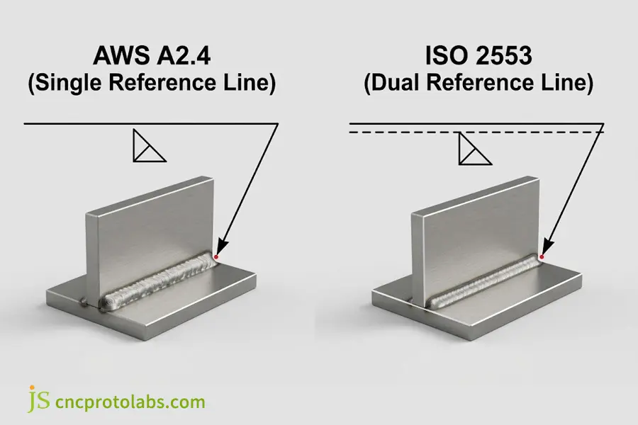
Multiple Reference Lines for Sequential Operations
Complex joints frequently require a series of operations performed in a specific order. Designers indicate this by placing several reference lines on a single arrow:
- First Line (Closest to the arrow): Indicates root pass, back gouging or the fit-up process.
- Second Line (Middle level): Controls the fill passes or second welding run.
- Third Line (Furthest from the arrow): Specifies final cap passes or non-destructive testing requirements.
Line order is critical and must be followed from the arrow tip outward. Skipping steps compromises joint integrity.
How to Accurately Interpret the Weld Symbol Chart and Fillet Weld Symbol Dimensions?
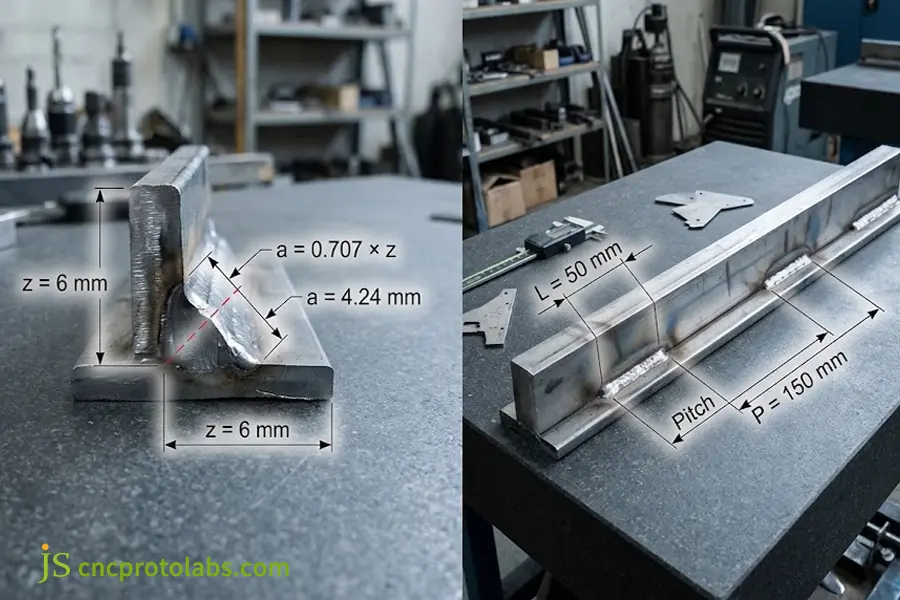
Interpreting a weld symbol chart is as simple as translating joint geometry to the symbols on the chart, most commonly the right-triangle fillet weld symbol. To the left are dimensions of leg size (z) or groove depth (S). To the right are dimensions for weld length (L) and pitch spacing (P). Unequal legs are listed in parentheses to ensure adequate throat thickness (a ≥ 0.707 × z).
|
Basic Weld Symbol |
Graphic Icon Shape |
Left-Side Dimension |
Right-Side Dimension |
|
Fillet Weld |
Right-angled triangle (vertical leg on left) |
Leg size z (e.g., 6 mm) |
Segment length L and pitch P (e.g., 50-150) |
|
V-Groove Weld |
Angled V profile |
Groove depth S and throat size (E) |
Seam length (runs full length if blank) |
|
Square Groove |
Two parallel vertical bars |
Root face thickness |
Seam length |
|
Plug / Slot Weld |
Rectangle or diameter circle |
Hole diameter or slot width |
Slot length and spacing |
|
Spot / Seam Weld |
Circle or parallel-line oval |
Spot diameter or shear strength |
Pitch spacing between weld centers |
Edge preparation specifications must align with established weld joint design parameters to ensure complete structural load transfer.
The Left-Right Dimensional Principle
Dimensions shown adjacent to the welding symbol are governed by the following rules:
- Left Position (Cross-Sectional Size): In case of fillet welds, this gives the dimension z for leg length. In groove welds, the S (E) notation is used, S refers to preparation size while E stands for effective throat thickness requirement.
- Internal Geometry (Root Opening and Included Angle): Root opening R is directly adjacent to groove symbol (e.g., 2 mm). While included angle is directly outside the profile (e.g., 60°).
- Right Position (Length and Spacing): Determines the seam length and pitch of welds. If there are no dimensions on the right side of the symbol, the weld shall extend along the whole seam.
Continuous vs. Intermittent Welds
Where the assemblies do not need to be fluid-tight, the intermittent welding process is applied to avoid overheating and consequent distortion of the assembly. These callouts follow an L - P format, where L is segment length and P is center-to-center pitch:
- Callout Format: A callout of 6 | 50-150 refers to a 6 mm leg fillet welded in 50 mm long sections separated by 150 mm center-to-center.
- Chain Intermittent: Equal dimensions that appear directly opposite each other on either side of the centerline call for mirror image weld segments.
- Staggered Intermittent: Offset measurements prescribe weld segments to alternate on opposite faces of the plate in a zig-zag pattern.
Rules for Throat Thickness
In symmetrical fillet welds, the structure load is borne by the effective throat thickness (a), which is the shortest distance from the joint root to the face of the weld:
a = z × cos(45°) ≈ 0.707 × z
A 6 mm leg fillet has a theoretical throat thickness of 4.24 mm. If you under-size the leg, you compromise the throat and risk joint shear failure under heavy tensile loads.
Welding assemblies with high dimensional repeatability needs close integration with upstream sheet metal fabrication steps such as laser cutting and CNC press brake forming.
What Critical Risks Arise from Misinterpreting the Field Weld Symbol and Supplementary Marks?
Incorrect interpretation of field welds flag, all-around circle, and finish contour symbols results in major assembling problems. The symbol of a black flag placed at the intersection of the arrow and reference line shows that the field weld has been done in situ during the assembly process. Failure to notice this symbol will cause assembling at the shop level, making the parts too big to transport.
To maintain structural reliability, engineering drawings and welding procedures must follow recognized standards, such as AWS A2.4 (Standard Symbols for Welding, Brazing, and Nondestructive Examination).
Decoding Supplementary Symbols
Supplementary symbols offer guidance on how to execute work at the intersection of reference lines:
- Field Weld Flag: A small flag positioned perpendicular to the reference line, pointing away from the arrow. The weld is carried out on the field while installing, not in the workshop.
- Weld All-Around Circle: An open circle located at the elbow joint, calling for welding around the entire joint.
- Backing and Spacer Blocks: A rectangular symbol opposite a groove, suggesting backing strip support. An 'R' within the symbol denotes that the backing needs to be removed after the welding process.
- Melt-Through Symbol: A half-circle symbol opposite a groove symbol, demanding controlled root reinforcement on the backside.
- Contour and Finish Marking: Surface finish marks positioned above the basic symbols with processing technique letters (G for grinding, M for machining, C for chipping).
Three Costly Drawing Misinterpretations
1. Pre-Assembling Field Welds in the Shop
- The Error: a fabricator mistook a field weld flag for no weld on structural support brackets and set them in place with a weld before delivery.
- The Impact: During installation, the weld blocks access to the anchor bolts and goes beyond the allowable clearance of 2,438 mm on road transit.
- The Cost: To remove the brackets, the erection crew had to torch-cut them out, finish grind the surfaces, and re-weld on-site, pushing commissioning out by 2 weeks.
2. Excessive Heat Distortion due to Large Fillets
- The Problem: A fillet specification of 4 mm was incorrectly interpreted as 8 mm, increasing the weld deposition by four times (8 / 4)² = 4.
- The Effect: The excessive depositing of four times more material than was originally intended to be placed on a 2 mm thin 304 stainless steel frame created an excessive amount of localized heat.
- The Cost: The flanges of the mountings were pulled out of flat by 4.5 mm (more than 0. 8mm flatness tolerance) and the whole assembly was disposed off.
3. Skipping All-Around Weld Instructions
- The Mistake: The operator did not weld the all-around circle of the drawing elbow. Only the top and bottom surfaces of the joint were welded.
- The effect: Substantial stress concentrations formed at the open side seams under cyclic torsional loading.
- The Cost: Fatigue cracks initiate in 15,000 cycles through the heat-affected zone, proving the need for continuous perimeter sealing.
Pre-inspecting prints before manufacturing helps prevent dimensional scrap of components. For more complex components, collaboration with reliable suppliers of precision metal fabrication services enables an engineering review, welding sequence control, and inspection services before the parts are even made.
FAQs
What is the distinction between a weld symbol and a welding symbol?
A weld symbol refers to the exact shape of the weld cross-section such as fillet, V-groove or plug.
On the other hand, a welding symbol is the entire schematic instruction for welding. This comprises reference line, arrow, basic weld symbol, dimensions, finish contour and process tail. Weld symbol is just one part of a whole welding symbol.
Does a triangle symbol on a drawing always mean a fillet weld?
Yes, the right angled triangle that is drawn on the reference line represents fillet weld.
As per AWS and ISO standards, vertical leg of the triangle will always be on the left side irrespective of the direction of the arrow. The number written on the left side of the triangle represents the leg length.
What does the tail on a welding symbol indicate?
The tail is an optional V-shaped fork at the end of the reference line.
This fork may include important information related to welding processes, such as alloy of filler metals, or test requirements, such as GTAW (TIG) or UT. Tail is not included if there are no special instructions, because standard shop procedures are used.
Why should the vertical line of the weld symbol be always on the left?
According to the drafting conventions, the vertical leg of fillet, bevel, and J-groove welds should be placed on the left.
This way, the drawing remains readable, regardless of whether the arrow points to the left, right, upward or downward. Putting the vertical line on the right breaks the drafting conventions and confuses shop personnel.
How are pitch and length read on an intermittent weld symbol?
On intermittent welds numbers to the right of the symbol are shown in an L - P form.
The top number (L) is the length of each weld segment. The second number (P) is the pitch or the center-to-center distance between the weld segments. If numbers are staggered above and below the line, they are on opposite sides of the joint.
What does a circle at the elbow of a welding symbol mean?
Open circle on the intersection of arrow point and reference line indicates a weld all-around note.
It instructs the welder to deposit a continuous weld around the entire border of the joint without stopping, for example at pipe joints or mounting plates.
Conclusion
When applying drawing principles on the fabrication shop floor, the result is a seamless transition of the design intent to a fabrication structure through an engineering process. The review of the reference lines, arrow side, leg-throat connections, and field weld flags minimizes the need for dimensional revisions, mitigates heating distortions, and maintains structural tolerances.
Successful component manufacturing requires balancing these geometric symbol callouts with realistic sheet metal clearances and edge tolerances. To deepen your understanding of how groove preparation, weld penetration, and assembly fit-up interact on the factory floor, exploring our detailed engineering resource on metal welding offers practical benchmarks for setting up robust fabrication workflows.
Resource