English



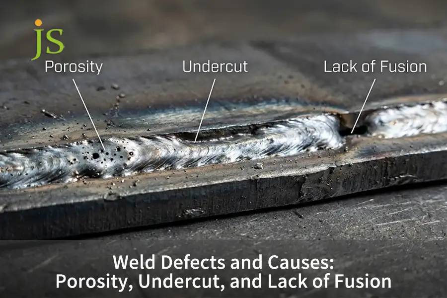

Common welding defects and causes first and foremost result from incorrect heat input, surface contamination, insufficient shielding gas coverage, and poor joint fit-up. Welding defects causes like porosity arise when gas pockets become trapped in the molten weld pool during rapid solidification. Undercut occurs when high arc voltage or excessive travel speed melts away the base metal toe without adequate filler metal backfill. Conversely, lack of fusion happens when the arc fails to melt the joint walls before depositing filler metal. Understanding these root causes is essential to prevent structural rejects in compliance with AWS D1. 1 specifications.
Key Weld Defects, Causes, and Prevention
Key Takeaway: Welding defects mostly come from the heat balance, shield loss, and joint gap problems, but proper voltage range setting, gas flow rate, and cleaning processes can solve most welding problems on the shop floor.
| Defect Type | Root Cause | Critical Parameters | Prevention Rule |
| Porosity | Gas turbulence or surface grease releasing hydrogen | Gas purity ≥99.99%, flow 12–18 L/min | Clean base metal ≥25 mm from joint, shield crosswinds >2 m/s |
| Undercut | High arc voltage and fast travel speed scouring plate edge | Voltage tolerance ≤±1.5 V, angle 10°–15° | Reduce travel speed, pause 0.5–1.0 s at joint edges |
| Lack of Fusion | Narrow bevel, zero root gap, or low heat input | Heat input ≥0.8 kJ/mm, groove ≥60° | Keep root face ≤1.5 mm, grind interpass scale and slag clean |
What Are Common Weld Defects and Causes in Industrial Fabrication?
Common weld defects and causes arise from thermal, chemical, and physical imbalances within the molten pool during cooling. Any variance between actual arc values and those specified in the Welding Procedure Specification will affect cooling rates to a very great extent. Thermal imbalance may cause gas entrapment, prevent sidewall fusion, or even damage parent metal toes. Maintaining constant travel speed, proper voltage, and good joint fit-up avoids more than 90% of welding failures.
Engineers determine the category of welding defects based on the AWS A3.0 Standard Terms and Definitions. Discontinuities, which are described as changes in the mechanical or metallurgical structure of the weld, qualify as defects when they exceed tolerances prescribed by engineering drawings. Review the process of metal welding.
Three Fundamental Physical Processes That Lead to Weld Failure
There are three basic physical phenomena that determine whether the weld deposit is intact or not:
- Surface Tension Gradient (Marangoni Convection): Temperature differences between the arc center and the weld flanks cause flow circulation. High flow velocity carries the liquid metal in the opposite direction from the joint borders, resulting in empty spaces.
- Gas Solubility Drops (Sieverts' Law): The molten pool metal is highly saturated with hydrogen, oxygen, and nitrogen. When cooling down, the solubility decreases rapidly. The bubbles are trapped if the freezing speed is higher than the bubble rising speed.
- Heat-Affected Zone (HAZ) Thermal Shocks: The heat-affected zone (the zone that undergoes structural changes due to heat exposure but does not melt) experiences thermal shocks. Inappropriate preheat results in hardened structures of martensite, shrinkage stresses, and micro-fissures.
Welding defects arise in situations where the weld metal freezes without releasing the trapped gas, filling the corner of the joint, and melting into the base metal.
What Are the Primary Weld Porosity Causes and Prevention Methods?
Weld porosity causes typically involve volatile gases dissolving into the molten pool and failing to escape prior to rapid solidification. Drawing lubricant, humidity in the air or a turbulent shielding gas flow that exceeds 20 L/ min (causes fluid turbulence) can trap spherical or wormhole voids dew points in the -40 C range or less and chemical degreasing ensures to density reaches to ISO 5817 Level B standard, while balancing heat input avoids welding heat distortion and DFM problems with thin sheet metal fabrications.
The Physical Appearance of Porosityc
Porosity decreases the load-carrying cross-sectional area of the weld, which creates stress concentration due to fatigue loading:
- Uniformly Scattered Porosity: Scattered microscopic holes created due to wetting of the electrode or poor coverage by the shield.
- Clustered Porosity: Clusters of holes created due to unstable start and stop of the arc, or dragging of the electrode outside the shield area.
- Linear Piping Porosity (Wormholes): Long gas tunnels created due to excessive gas creation in fast-freeze passes.
Contamination by Hydrogen and Moisture
Hydrogen is the leading cause of porosity in carbon steel and aluminum welds. Moisture decomposes due to arc heat to form hydrogen and oxygen, both of which can be dissolved easily by the liquid pool.
- Storage Humidity: Store raw plate at less than 60% relative humidity.
- Consumable Baking: Preheat the stick electrodes (SMAW) to 250 °C to 350 °C for 1 hour before striking an arc.
- Mechanical Preparation: Remove mill scale, rust, oil, and paint at least 25 mm from the edge of each groove.
Flow Velocity of Shielding Gas and Turbulence
The arc needs uninterrupted gas cover in order not to have contamination from the atmosphere:
- Low Flow (Below 10 L/min): Outside air gets into the path of the arc resulting in nitrogen porosity and iron oxide.
- High Flow (Above 20 L/min): The high velocity of the gas flow results in low pressure, creating a vacuum (Venturi effect), which pulls air right into the pool.
- Shop Crosswinds: Air currents over 2 m/s speed pull the protective gas column away from the arc. Use physical barriers to protect your station.
Porosity occurs when oil, water, or air gets into gaseous state inside liquid steel and gets stuck during solidification of metal.
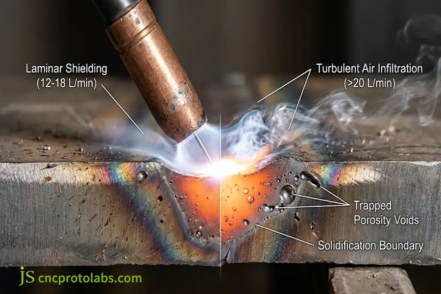
Cross-section schematic illustrating weld porosity causes due to turbulent shielding gas flow and ambient air infiltration (AI Generated).
What Are Undercut Welding Causes and Process Corrections?
Undercut welding causes center on excessive arc voltage and extreme travel speeds scouring the parent plate without adequate filler backfill. Too much electromechanical arc force drives the liquid metal away from the weld toes, leaving grooves that exceed 0.5 mm in depth. Stable travel speed at 250–350 mm/min and torch angle of 10°-15° prevents early toe grooving.
Risk of Geometric Damage Due to Weld Gouge
The undercut is a sharp mechanical notch that exists around the weld seam. When subjected to cyclic loading, there is a sudden increase in local stress concentration (Kt ≥ 2.5), which initiates fatigue crack formation prematurely.
Recommended GMAW Process Windows to Prevent Weld Toe Undercut
Important Note: Limiting travel speed under the specified values and voltage selection ensures no arc gouging occurs.
|
Plate Thickness (t) |
Welding Current (A) |
Arc Voltage (V) |
Max Safe Travel Speed |
ISO 5817 Limit (Max Depth) |
|
1.5 mm Sheet |
70–95 A |
16.5–18.0 V |
400 mm/min |
Short flaws permitted: depth ≤0.2 mm |
|
3.0 mm Plate |
130–160 A |
19.0–21.0 V |
350 mm/min |
Level B limit: depth ≤0.05 t (max 0.3 mm) |
|
6.0 mm Plate |
210–250 A |
23.5–25.5 V |
280 mm/min |
Level B limit: depth ≤0.05 t (max 0.5 mm) |
|
≥10.0 mm Section |
280–340 A |
27.0–30.0 V |
220 mm/min |
Smooth transition required, max depth 0.5 mm |
Voltage, Heat, and Arc Plasma Forces
Arc voltage dictates the actual size of the electric arc. With high voltage, the arc becomes wider:
- Arc Broadening: The wide arc causes premature melting of the shoulders at the top of the groove.
- Melt Displacement: This melted metal gets pushed from the arc into the middle of the weld puddle.
- Premature Freezing: The puddle freezes before liquid metal flows back out to refill the toe edges.
- Corrective Window: Lower voltage by 1.5 V to 2.5 V to concentrate the arc root into the joint.
Torch Angles and Travel Speed Dynamics
- Travel Speed Limits: Welding beyond 450 mm/min creates a puddle behind. The molten groove gets cooled by then before the filler metal fills it up.
- Torch Work Angle: While welding 2F position, tilting the torch upwards cuts the vertical plate. Keep the torch at a half 45° angle.
- Weave Pause Time: While weaving, keep the torch still for 0.5 to 1.0 second at each side to completely add filler metal in the toe of the joint.
Undercut occurs due to high temperature of the torch and a high speed, which results in cutting an empty groove in the plate and not having enough filler metal deposited in it.
How Do Lack of Fusion Welding and Slag Inclusions Develop?
Lack of fusion welding and slag inclusion defects arise when heat fails to breach joint surfaces or molten flux gets trapped between successive beads. Inadequate bevel angles less than 50 degrees or presence of mill scale physically inhibit atomic bonding. Proper opening of root gap up to 1.5–2.5 mm and cleaning of slag between weld passes will ensure penetration through heavy steel joints. Detailed weld joint design and fit-up parameters can prevent these joint bridging issues.
The Three Critical Types of Incomplete Fusion
Unlike surface porosity or undercut, lack of fusion welding represents an internal plane of zero metallurgical bonding:
- Sidewall Lack of Fusion: In this case, the filler metal slides over the bevel face without causing any melting of the base material.
- Interpass Lack of Fusion: The new weld passes over the old welds without melting in them.
- Root Lack of Fusion: This happens when the root bead does not melt the bottom edges of the base material.
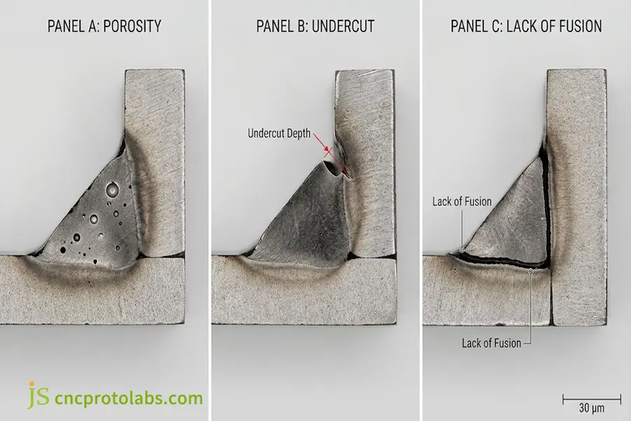
Macrograph comparison displaying cross-sections of porosity, undercut, and lack of fusion defects (AI Generated).
Cold Filling and Insufficient Heat Input
Cold filling (filler material passing over solid substrate material) happens commonly in Short Circuit Gas Metal Arc Welding (GMAW-S):
- Low Current Settings: Operator decreases current value in order to avoid spatter or burning of material in thin sheets.
- Low Thermal Energy: Wire burns into drops but there isn’t enough energy to melt the substrate plate.
- Adhesion Without Fusion: The molten metal rolls down the substrate similar to wax rolling on a glass sheet. Visually it is uniform but under light bending it separates.
- Parameter Target: Make sure that calculated heat input (kJ/mm) is enough for plate thickness.
Joint Bevel Angles and Slag Inclusion
Narrow joints prevent the arc energy from burning deeply into the joint corners:
- V-Bevel Angle: When you cut the bevels at an angle < 50°, the arc will only bridge over the top without getting to the root area. Use bevel angles of ≥60°.
- Root Gap Spacing: No root gap between the clamping plates prevents penetration. Maintain root gap of 1.5mm to 2.5 mm using temporary spacers.
- Entrapped Slag: In the process of FCAW or SMAW, slag acts as a glassy layer inclusion formed over the hot weld metal bead. When the next bead is made without removing the slag, it gets entrapped. Clean each bead with a wire wheel or needle scaler.
Fusion lack occurs when the base plate is not melted but just sitting on the weld wire; slag inclusion occurs when you bury glassy slag rather than cleaning it before making the next bead.
Why Do Standard Controls Eliminate Root Welding Defects Causes?
Systematic prevention of welding defects causes relies on combining qualified Welding Procedure Specifications (WPS) with rigorous quality checks before welding, during the process, and after completion. Standardizing bevel geometry, ensuring wire cleanliness, and applying non-destructive testing (NDT) eliminate operator variability. Maintaining strict process control over fixtures and heat parameters ensures zero-defect structural assemblies in demanding production settings.
Phase 1: Pre-Welding Setup and Consumables
- Joint Surface Cleaning: Remove rust, laser oxide, and moisture. Clean up the welding area with acetone.
- Inspect Fit-up: Ensure that the faces of root are between 1.0 mm to 1.5 mm and verify that the root clearance is as per drawings.
- Store Consumables: Ensure low hydrogen rods are stored in warming ovens above 120 °C.
Phase 2: In-Process Welding Controls
- Monitor Heat Input: Calculate heat input using standard parameters:

- Control Interpass Temperatures: Stainless steel interpass temperature should be kept below 200°C to avoid formation of carbides. Structural steels should be kept above 100°C to avoid hydrogen embrittlement.
- Check the Supply of Gas: Use a portable flow meter to check the flow of gas at the welding torch nozzle, rather than the cylinder regulator.
Phase 3: Non-destructive Testing after Welding (NDT)
Selection of NDT Techniques to Identify Imperfections in Welds
Key Takeaway: The combination of surface inspection with volumetric ultrasonic or radiographic inspection will identify both surface and subsurface weld defects.
|
NDT Inspection Method |
Target Weld Imperfection |
Detection Sensitivity |
Major Shop Floor Limitation |
|
Visual Testing (VT) |
Surface undercut, surface porosity, overlap |
High (surface flaws ≥0.2 mm) |
Detects surface discontinuities only |
|
Penetrant Testing (PT) |
Surface-breaking micro-pores, toe cracks |
High (surface openings ≥1 μm) |
Requires clean chemical pre-wash, surface only |
|
Ultrasonic Testing (UT) |
Sidewall lack of fusion, deep laminations |
High (volumetric & planar flaws) |
Dependent on probe angles and technician skill |
|
Radiographic Testing (RT) |
Internal piping porosity, dense slag pockets |
High (volumetric voids ≥1% thickness) |
Requires radiation containment, misses tight planar cracks |
Weld defect elimination involves cleaning the steel, maintaining high standards of electricity specifications, and finally checking the weld through the appropriate test instruments.
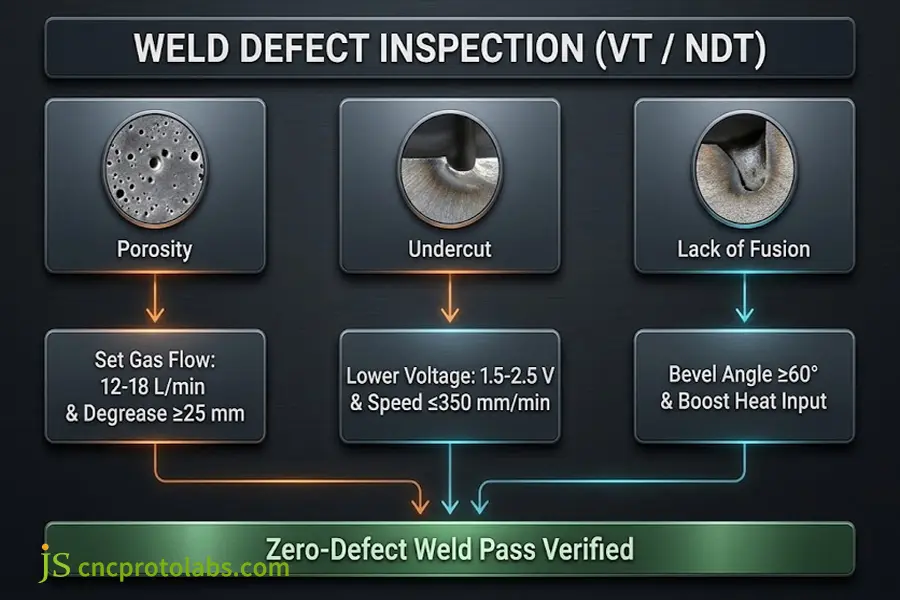
Industrial troubleshooting flowchart showing corrective actions for weld defects and causes (AI Generated).
FAQs
What causes porosity in welding?
Porosity is due to bubbles of nitrogen, hydrogen, or oxygen entrapped within the freezing puddle. Major sources of porosity are moisture, oily edge of the plate, wet electrodes and drafts over 2m/sec dragging gases out of the shielding. Degreasing as well as laying, baking, and using draft screens avoids entrapping bubbles.
Why does undercut happen in welding?
The high arc voltage and the fast travel speed cause melting of the base metal edge faster than the filler material is able to fill it. The fast arc blows out metal from the toes. A reduction of 1–2 volts in arc voltage and the travel speed prevents edge gouging.
How to prevent lack of fusion?
Welding current should be increased, groove angles widened up to 60°, and the root opening should be kept at 1.5–2.0 mm. The arc should be directed towards the edges of the parent plate for its thorough melting.
How does shielding gas flow rate affect weld porosity?
The flow rate for shielding gas should be kept to between 12 to 18 L/min for standard nozzle. Lower flow rate allows entry of air within the arc, while flow rates exceeding 22 L/min cause turbulence, which draws in atmospheric air resulting in worm holes within the pool.
Can visual testing (VT) detect internal lack of fusion?
The lack of fusion can only be detected through Visual Testing (VT), when the defect occurs at open toes or root pass, but subsurface lack of sidewall fusion cannot be detected since it exists within the multi-pass joints and needs Ultrasonic Testing (UT) or Radiographic Testing (RT).
What is the main difference between slag inclusion and porosity?
Porosity is made up of hollow cavities created by the gases, while slag inclusion defects are solid particles of a glassy substance. Porosity arises from atmospheric contamination, while slag inclusion results from bad slag removal.
Conclusion: Control of Weld Defects in Precision Fabrication
Controlling porosity, under-cutting, and failure of fusion can be achieved by moving from post-weld inspection to controlling process parameters. By controlling heat input, joint fit-up dimensions, and gas purity, weld defect occurrence is kept below 1.5%. The adoption of the welding procedure specification eliminates welder inconsistency and guarantees that the welded product will comply with its mechanical properties.
Putting these tolerances and joint standards into practice requires disciplined shop-floor execution. Learn how our team handles strict welding criteria and assembly specs through our sheet metal welding services.