 English





Wall thickness optimization service evaluates plastic part designs to ensure proper flow uniformity and prevent sink marks. Furthermore, this precision DFM analysis helps injection molders reduce cooling cycles by up to 30%. Wall thickness optimization service can also reshape difficult-to-mold shapes into moldable, economical parts suitable for high-yield manufacturing.
At JS Precision, our DFM injection molding service is based on the latest developments and focuses directly on resolving the issues arising from shrinkage mismatch and deviation in volume, to produce reliable mass-produced items.
Wall Thickness Optimization Service Quick Reference
|
Polymer Class |
Recommended Wall Thickness |
Rib-to-Wall Ratio |
Max Shear Rate |
|---|---|---|---|
|
ABS (High-Flow / FR) |
1.20 – 3.00 mm |
40% – 50% (R0.6 corner) |
< 50,000 s⁻¹ |
|
PC (High-Strength / Amorphous) |
1.50 – 3.50 mm |
30% – 40% (R0.5 corner) |
< 40,000 s⁻¹ |
|
PA66 + 30% GF (Crystalline) |
1.00 – 2.50 mm |
35% – 45% (R0.8 corner) |
< 60,000 s⁻¹ |
Key Findings
- Main Cause of Asymmetric Warpage: Rapid and dramatic decrease in wall thickness of part exceeding 25% results in uneven volume shrinkage which is the physical basis of plastic parts warpage.
- Rib Shrinkage Prevention Rule: For the main wall thickness of crystalline materials, the thickness at ribbon base should be limited below 40%, and a 0.5 mm radius fillet is recommended to relieve internal stress and residual stresses from molding.
- Thick Area Hollowing and Optimization: The solid portions, being the heaviest, are preferably converted into hollow or boxlike structures and are reinforced with cross-ribs achieving 35% reduction in weight and the simultaneously 20% increase in stiffness of bending.
Why Opt For JS Precision’s Custom Mold Engineering Services For Wall Thickness Distribution Design?
Based mainly on the injection mold team of our company with over 15 years' worth of experiences, we understand that a real partner who can provide wall thickness optimization services should have 3D closed-loop capabilities: material flow simulation, mold stiffness compensation, and mass production process stability. From our drone casing experience, we have found out that if a design has wall thickness changes larger than ~25%, high-flow-rate materials do not help warpage to be resolved solely by manufacturing-process-adjustment - one has to start the solving of the problem at the design stage.
ISO 9001:2015, Quality Management Systems, says: An organization shall identify the necessary processes and their implementation throughout the organization and determine the sequence and interaction of these processes.
From compliance with this requirement, we carry out a 3-level Design for Manufacture (DFM) review in every wall thickness optimization effort, so that the wall thickness decision-making is properly documented throughout the development.
We had a drone housing project where we replaced the sudden wall thickness changes from 1.2 mm to 4.5 mm with consistent 1.8 mm thickness wall and added 0.8 mm cross ribs. Warpage had been reduced from 1.5 mm to <0.1 mm, cooling time was cut down from 35 seconds to 21 seconds, and production cost dropped by 35%. This approach has been developed into JS Precision's wall thickness optimization project portfolio containing more than 200 files of cases.
Download the Wall Thickness Optimization DFM Design Guide to master transition slopes, rib proportions, and hollowing-out strategies, helping you assess the engineering depth of your DFM injection molding service.
How Does Abrupt Wall Thickness Variation Cause Warpage and Sink Marks in Injection Molding?
DFM injection molding service should be able to handle the problem of cooling rate difference caused by the wall thickness change. Thicker parts cool down slower, while thinner parts cool rapidly. As a result, an asymmetry in volumetric shrinkage and residual stress is created. Finally, both surface shrinkage and overall warping are produced.
Physicochemical Reasons of Difference in Volumetric Shrinkage
ΔVshrink=α×(Tmelt−Tmold), where the Greek character alpha (α) is coefficient of linear expansion of the material, which shows that larger the temperature difference, more the shrinkage due to local wall thickness variations.
Taking PC as an example, α is about 70 × 10 ⁻⁶/℃. When the temperature difference between the thick and thin areas reaches 30℃, the difference in volume shrinkage rate can reach 0.21%, which is sufficient to produce warping of more than 0.2 mm on a 100 mm long part. Simply put, this means that the greater the difference in wall thickness and the lower the mold temperature, the exponentially higher the risk of warping.
Transition Solutions Comparison
- Traditional Approach (Direct Wall Thickening):
There is no transition design but the area only changes the wall thickness gradually, i.e. There is only the round corner design from one part to another. The shift of the thermal center towards the part with a thicker structure results in the generation of shrinkage lines deeper than 0.3 mm. In extreme cases like this Still seal failure due to dimensional mismatch or rejection of the product due to its looks may still happen even after the assembly.
- JS Precision Solution:
A smooth, gentle slope (Transition Taper ratio 1:3 to 1:4) design allows for the equal distribution of heat. The degree of shrinkage is less than 0.05 mm which is practically not visible to our eyes. We also do a 0.5 mm R at the foot of the transition part to help relieve the stresses.
Contact JS Precision's senior mold engineers immediately for a free wall thickness transition DFM assessment to validate the design rationale of your custom injection molding supplier.
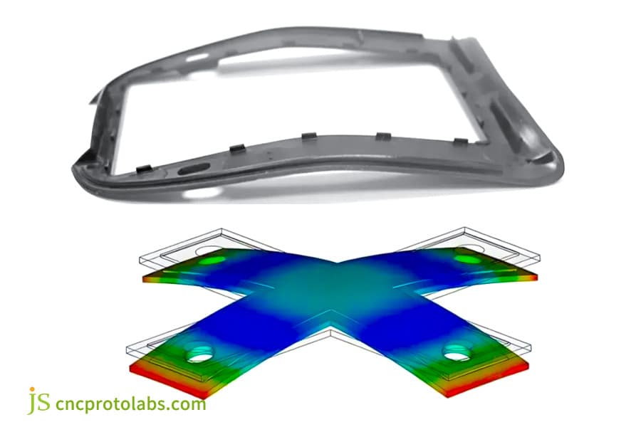
Figure 1: Colorful engineering plastic resin pellets in glass tubes for material testing.
What Are the Minimum and Maximum Wall Thickness Limits for Common Plastic Resins?
The core of part design for moldability is to understand the flow limits of different resins. Amorphous types of plastic like PC need a wall thickness of at least 1.5 mm to avoid being short-filled while crystalline plastics like PP/PA66 can be molded with very fine walls as thin as 0.8mm through very well-controlled conditions. Still, when making the mold design, the influence of the flow length (L/T ratio) cannot be ignored - if L/T is greater than the guideline it could lead underfilling even if the wall thickness is correct.
Common Engineering Plastics Wall Thickness Limits Table
|
Material |
Min Wall (mm) |
Max Wall (mm) |
Recommended L/T Ratio |
|---|---|---|---|
|
PP (Homopolymer) |
0.80 |
3.00 |
150:1 |
|
PA66 + 30% GF |
1.00 |
2.50 |
100:1 |
|
ABS (High-Flow) |
1.20 |
3.00 |
120:1 |
|
PC (General Purpose) |
1.50 |
3.50 |
80:1 |
|
POM (Copolymer) |
1.00 |
3.00 |
130:1 |
Resin - Unfilled Pure Limits
If you look at pure PC you find it's quite sensitive to variations in wall thickness. Below 1.0mm the flow resistance increases rapidly so scorching due to shear overheating is likely. Also PC has a strong tendency to show molecular orientation in thin-walled parts that leads to anisotropic shrinkage and higher probability of warping. In the initial stage of injection mold tooling service, it is necessary to jointly lock the safe wall thickness based on MFR and L/T ratio, rather than relying solely on empirical estimation.
Boundaries of Glass Fiber Reinforced Resins
Polyamide 66 (PA66 + 30%GF) by using glass fiber controls shrinkage but simultaneously it elevates viscosity. If wall thickness is less than 1.2 mm, there will be exposure of fibre (fibre floating) making the surface very rough. Fibres floating not only destroy the looks but also create stress concentration points which reduce the fatigue life.
Through the JS Precision's custom mold engineering service we can set a reasonable minimum wall thickness from the start that is dependent mainly on a given resin type and glass fibre concentration, risk of fibre float is also determined with mold flow analysis, so mold rework is avoided that may be very expensive.
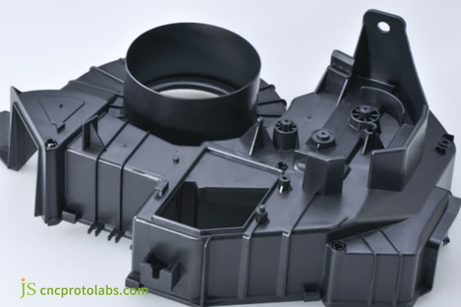
Figure 2: Diagram illustrating injection molding shrinkage causes and warped part results.
How Can We Design Ribs and Gussets to Avoid Increasing Global Wall Thickness?
The injection mold design optimization essentially hinges on introducing ribs (equal to 40% or 60% of the main wall thickness) and support plates at thin walls which will result in greatly increased structural strength without needing either to increase the total wall thickness or to extend the cooling time. Then again, thicker ribs don\'t necessarily give better results - the thick ribs to a degree can cause the creation of hot spots at the root which will further result in shrinkage.
Three main geometrical rules for rib stiffening:
- Rib Base Thickness: Should be 0.4 - 0.6 times the main wall thickness. For crystalline materials the minimum limit of 0.4 times is advised as this will limit the risk of shrinking.
- Rip draft angle: shouldn't be less than 0.5°, For depths exceeding 10 mm, a 1 draft angle is to be preferred to prevent sticking to the mold.
- Radius at the rib root: 0.4 mm - 0.8 mm so that it could help eliminate stress concentration. A too small radius will lead to stress cracking, whereas too large a radius will, not only create a shrink, but increase even a local wall thickness
Option A (Blindly Thickening) vs. Option B (JS Precision Rib Optimization)
|
Parameter |
Option A: Overall Thickening |
Option B: Rib Optimization |
|---|---|---|
|
Main Wall Thickness |
2→4 mm |
Maintain 2 mm |
|
Weight Change |
+100% |
+15% |
|
Cooling Time |
12→38 s |
12 s |
|
Stiffness Gain |
Limited |
+300% |
|
Sink Risk |
High |
Low |
Option B gives a three-fold increment of the stiffness, the reason is the ribs which focus the materials on the outer side of neutral axis where maximum stress occurs instead of spreading the materials homogeneously over the whole cross-sectional area. The ability to use topology optimization like this is the major feature that sets aside of high precision mold manufacturers compared to regular mold factories.
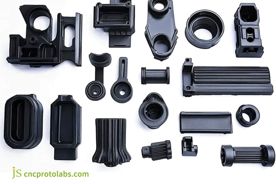
Figure 3: Transparent custom plastic component with polished surface and injection mold.
How Can Mold Flow Analysis Service Predict and Solve Thickness-Related Molding Defects?
The mold flow analysis service accurately simulates the flow, holding pressure, and cooling process of molten plastic within the mold cavity to predict weld lines, trapped air, and warpage that might result from uneven wall thickness. JS Precision uses Autodesk Moldflow software to calculate the molding risk, but remember that, software is only a tool, its true value is reflected in the way engineers interpret the results and turn them into better designs.
Main Findings of Moldflow Analysis:
- Pressure Drop Curve: Evaluates whether the end-fill pressure is high enough. Generally, the end-fill pressure must remain at least 30% of the injection pressure because otherwise, short shots might happen.
- Condensate Ratio: Checks the weld strength and surface appearance. In places where the condensate ratio exceeds 50%, weld strength may decrease to 60% of the body strength or below.
- Cavitation Risk Map: Highlights sites of trapped air and assists with the venting design. Cavitation sites should be matched with venting channels. When this isnt done, trapped air may cause scorching or short shots.
Holding Pressure Curve & Wall Thickness Fine-tuning:
By identifying the wall thickness at the point where the holding pressure curve changes its gradient, engineers fine-tune part wall thickness for maximal holding pressure transfer which reduces internal stress. Suppose the holding pressure curve steeply falls at 90% fill, indicating that the material volume in that area is too small.
One must increase the wall thickness in that area by 0.2-0.3 mm so that the holding pressure transfer is properly achieved. Mold flow analysis provided by the injection mold tooling service is the final step before mass production and also the most practical way of minimizing the number of trial molds.
How Should Thick Plastic Sections Be Core Outed to Eliminate Void Risks?
Custom mold engineering service include creating thick-wally areas turned into evenly thin-walled or even double-wall structures, with diagonally or cross-wise reinforcing ribs inside the cavity for structural support. When cooling down, the surface solidifies first leaving behind the core melt that extends and contracts toward the exterior, leading to cavities and shrinkage. This type of defect is commonly seen whenever the wall thickness is over 4 mm, and whether material used is not a factor to affect that.
Solid Cylinder Compared to JS Precision Hollowed-out Design
- Solid Cylinder (Ø10 mm): The internal vacuum caused by the plastic tensile will result into pore which will further reduce the material strength by 40% besides causing a dent in it. Porosity is a major structural deficiency. At the same time, it is often the case that the weakest point initiating stress corrosion also turns out to be the very one having porosity.
- JS Precision Hollow-out Design (Ø10 x inner 6 x wall thickness 2): When incorporated with 4 blade reinforcements, it delivers internally void free, smooth surface, an increase in gripping force (+25%) and material saving (-36%). Also, thanks to this design, the cooling time is slashed from 35 to 18 seconds because the uniform wall thickness gets rid of the hotspots.
View more real-world industrial-grade injection molding success stories from JS Precision and learn how custom mold engineering service eliminates the risk of porosity.
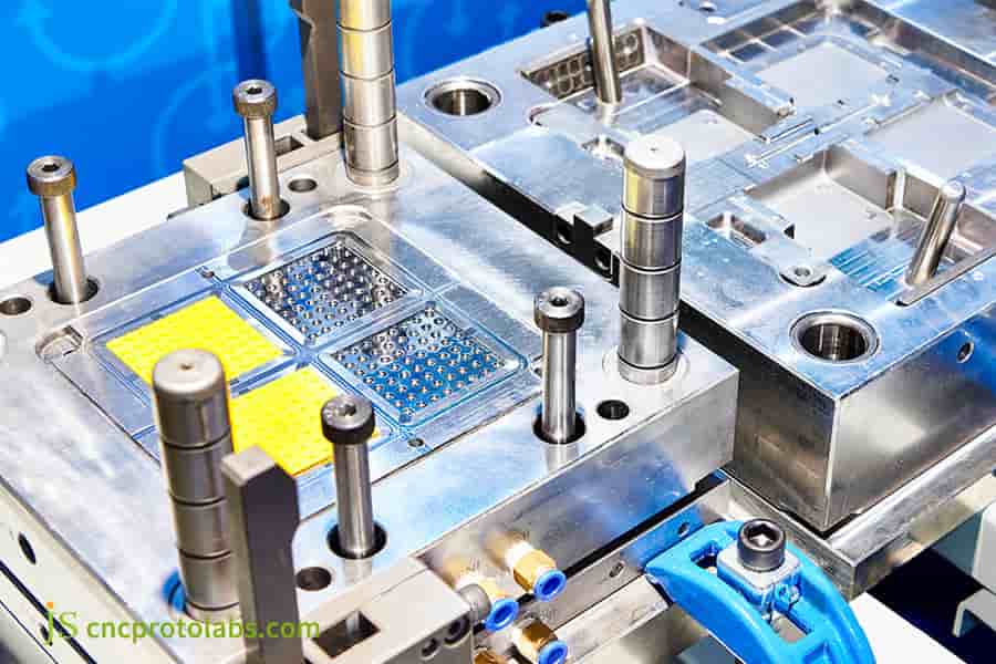
Figure 4: Close-up of a metallic injection mold cavity showing detailed gate design.
What Is the Geometric Relationship Between Draft Angles and Wall Thickness?
Wall thickness optimization service always considers draft angle. With the increase of wall thickness or cavity depth comes the increase of draft angle (usually +0.5°-1° per inch of cavity depth) to minimize mold opening and ejection sticking forces. That is because Truth is thicker walls shrink after cooling more, causing stronger core holding forces.
Wall Thickness-Draft Angle Ratio Recommendation Table
|
Wall Thickness (mm) |
Cavity Depth (mm) |
Min Recommended Draft |
|---|---|---|
|
1.0 – 2.0 |
≤10 |
0.5° |
|
2.0 – 3.0 |
10 – 20 |
1.0° |
|
3.0 – 4.0 |
20 – 30 |
1.5° |
|
>4.0 |
>30 |
2.0° + Texture |
For surfaces with sun patterns, the slope needs to be increased by an additional 0.5 ° on top of the above, as the texture increases demolding resistance.
Ejection Friction Comparison:
- Without or with Very Small Draft Angle<0.2°. Demolding is too resisted, surface getting scratches, ejection marks, and the defect rate reaches 15%. This type of defect is very often seen in deep cavity thin wall parts.
- JS Precision Ideal Draft Angle (≥1°+sun pattern): Ejection resistance is -70%, more than a 99.8% yield rate. Also to reducing the number of ejector pins, optimized draft angles result in less mold costs.
What Tooling Challenges Exist for Manufacturing Thin-Wall Plastic Components?
Thin-wall plastic components demand molds to have a high hardness mold steel, accuracy in air vent system, and high pressure capability. Injection units are set to a very high speed (>500 mm/s+) and a high injection pressure is necessary (>2000 bar+) when doing thin-wall injection molding. Molds of these types need to withstand the high pressure and have a high precision ventilation system.
Ultra-thin Part Condensation and Venting Control
Vent groove depth secret rule: too deep -> flashing, too small -> air cannot get out and the plastic burns (Diesel Effect). JS Precision keeps vented groove depth at 0.015-0.02 mm. S136 mirror steel (≥HRC 52) is selected to prevent mold fatigue wear from mold operation under both high frequency and high pressure conditions besides providing vent system reliability.
S136 HRC52+ Mold Steel Selection
To put it simply, highpressure injection of thin wall parts can mean mold wear and even deformation. The cavity is constructed using S136 at HRC 52+ together with a high precision venting system.
In such a case, the wall thickness tolerance remains ±0.02 mm after 500,000 cycles of molding. In contrast, regular mold steel (e.g. P20 at HRC 30) may develop surface wear after merely 100,000 cycles, which causes flashing and dimensional changes.
The accuracy of mold tooling manufacturing directly determines the success or failure of thin-walled parts. JS Precision uses slow wire EDM and mirror EDM on tooling so that all vented grooves are at the same depth and the parting surfaces fit very well.
Consult a JS Precision mold manufacturing expert one-on-one for your thin-walled project and get a customized solution for thin-walled plastic components.
How JS Precision Solved Warpage and Reduced Mold Tooling Cost by 35% for a B2B UAV Chassis
A commercial UAV buyer witnessed an unexpected change in shell wall thickness from 1.2 to 4.5 mm which caused warpage of 1.5 mm after the injection process, this made it impossible to produce the tight assembly gap. Before this, the customer tried to tweak parameters of the process which resulted in an increase of the holding pressure and a decrease of the mold temperature but the warpage was only minimized by 0.3 mm, still way below the 0.2 mm requirement for the assembly.
Customer Challenges and Their Root Causes
- Challenge: The multi-cavity shell's wall thickness changed dramatically from 1.2 to 4.5 mm, leading to a warpage of 1.5 mm and the complete failure of the assembly. The initial design featured a wall thickness of 4.5 mm in the area of the battery compartment whereas the edge was only 1.2 mm.
- Root Cause: Slow cooling in the thick zone and fast cooling in the thin zone caused a significant difference in volume shrinkage rate plus the residual stress. Mold flow analysis indicated that the temperature difference between the different areas was as big as 40℃ which resulted in a shrinkage rate difference of 0.35%.
JS Precision Solution
- Redesigning: In 3D DFM the thick shell wall was hollowed out making the main global wall thickness 1.8 mm (±5% allowable deviation). In the redesign, the battery compartment was changed into a hollow structure with a reinforcement of cross-shaped ribs.
- Rib Reinforcement: Reinforcing ribs, 0.8 mm thick and 1° angled, were distributed at stress concentration sites with the rib spacing being kept within 8 mm to ensure even support.
- Mold Flow Test: The gate has been moved from the thin wall area to a balanced wall thickness middle area so that the in-mold shear rate becomes <45,000⁻¹s. Cooling water channel layout optimization made a mold temperature uniformity of ±2℃ achievable at this stage.
Lessons learned:
The first version had very thin ribs at 1.0 mm. This led to air being trapped and the plastic was badly damaged during the high-pressure injection. In the second round, the rib width was decreased to 0.8 mm only with the addition of a 0.015 mm deeper overflow groove that also opened up the passage of the runner. This example shows that rib thickness doesn't always mean the best choice is the thinner ones, one reason too thin to allow the melt to flow and causes trapping of air.
ISO 294-3:2020 mentions: Injection molded specimens shall be prepared under controlled process conditions, and key process parameters (packing pressure, mold temperature, shear rate) shall be recorded and validated.
To fulfill the requirements, we employed a point at which the curve of packing pressure had changed direction and a shear rate of under 45,000⁻¹s as our strict final acceptance criteria in the trial molding phase of the UAV housing, and this had been identified as why for the great success of the trial molding after the second round of overflow groove modifications.
Final Results (Data References)
- Cooling Time: 35→21 seconds (-40%)
- Warpage: 1.5 →<0.1 mm (-93%)
- Mold longevity: Doubled (from 250,000 mold cycles to 500,000 mold cycles)
- Total cost per item: decreased by -35% (Savings of the material + faster cycle time + scrap rate was reduced from 8% to 0.5%)
Customer opinion: Through DFM improvement, JS Precision has enabled us to prevent hundreds of thousands of dollars in mold modification expenses.
Obtain DFM optimization solutions and trial mold reports for similar drone casings, upload drawings to JS Precision, and receive a free evaluation and injection molding quote within 24 hours.
Why Choose JS Precision as Your Partner for Injection Mold Tooling Service?
As experts in one-stop manufacturing, we help manufacturers avoid mistakes at the early stages of design with our mold flow simulations and DFM skills which are the result of a great wealth of experience over the years. This allows defects to be detected early on resulting in considerable time and cost savings. Our manufacturing partners in the automotive, medical and consumer electronics industries have already received 5,000+ molds, including more than 200 wall thickness optimization projects.
20 Years of Engineering and More than 5,000 Projects
We stock a comprehensive variety of raw materials including ABS/PC/PA66/PEI and can deliver products based on extremely thin wall thicknesses as little as 0.8 mm up to 10 mm thick completely hollowed-out walls.
Through the years we've gained an unparalleled ability to predict problems in mold tooling manufacturing by simply visualizing defects - so now we maintain a catalog with details on 300+ different molds with problems that could happen, so that we can find problems before production begins. As one such example, we routinely check the possibility of fiber float in glass fiber reinforced plastics and suggest changes of wallthickness when giving a manufacturability report in Design for Manufacturing (DFM) stage.
Inspection Capabilities and Delivery Standards
- ISO 9001:2015 quality assured production system, including delivery to every client of inspection report of entire dimensions for each lot.
- Inspection using Zeiss coordinate measuring machine and wall thickness deviation with accuracy of ±0.01 mm.
- Providing free DFM + Moldflow analysis together with quotation including suggested changes and risk warnings.
Our main goal for the delivery of injection mold tooling is a first trial molding is a success, not merely it is a feasible product. By our historical data, it clearly turned out that the molds that were fully analyzed for DFM and mold flow had a 92% first-trial molding pass rate, way above the industry average of 65%.
FAQs
Q1: Does JS Precision charge for wall thickness optimization and design for manufacturing (DFM) services?
JS Precision offers wall thickness optimization and Design for Manufacturing (DFM) analysis services completely free of charge. The only thing you need to do is to send us your 3D CAD file (STEP/IGS). We will then have your mold engineering expert produce and send you a complete DFM report including Moldflow analysis, part modification recommendations, and even offer you the quotation for free within 24 hours.
Q2: Why uneven wall thickness is a cause of surface sink marks?
Different thickness wall areas lead to variation in the cooling rate, with the thick wall area being slower to cool down compared to the outer frozen skin area. When the inner resin hardens last and draws in, if the outer casing is still soft, this external plastic skin will follow the shrinkage, resulting in pulling-in of surface material and the depression (shrinkage mark) being formed on the plastic part.
Q3: What are the design guidelines on the thickness difference between high and low flowability resins?
The high flowability materials like PP, PE, and PA66 are easier to melt, so their wall thickness design can have as low as 0.8 mm, conversely the highly viscous, less flowable materials, like PC, PMMA, or PEI, should experience material shortage when thin-walled, so the minimum wall thickness should not be less than 1.5 mm.
Q4: What is the way to strengthen the parts without adding wall thickness?
There is no necessity to increase the wall thickness since we can insert reinforcing ribs (with a height 3 times of wall thickness) or gusset (0.4-0.6 times of thickness of main wall) at weak areas to obtain the same strength.
Q5: What can be done to avoid stress cracking which occurs where the thick section and thin section meet?
The main idea is to make gradual change by having a smooth transition between the thick and thin sections. In general, a transition slope of 1:3 to 1:4 is acceptable (i.e. A transition zone of at least 4.5 mm if the change is from 1.5 mm to 3 mm). And, it is highly recommended to not have the inner corner radius lesser than 0.5 mm.
Q6: What wall thickness tolerances can JS Precision guarantee for precise electronics?
JS Precision uses a high-precision servo injection molding machine combined with an imported CMM as part of its inspection process. For small to medium-sized precision plastic parts, we are able to stably control the actual molded wall thickness tolerance within about ±0.02 mm, we can also maintain wall thickness uniformity at a deviation level of 3%.
Q7: What are the mold tool requirements for thin-wall precision components?
High-pressure injection molding of thin-walled parts easily causes mold deformation and wear. So, the mold cavity should be made of high-hardness, high-quality steel (for example S136 heated to HRC 52+) and be supplied with an extremely precise venting system (depth of channel 0.015 mm - 0.02 mm) in order not to let scorching happen.
Q8: What is the initial tooling cost and injection unit price for a custom mold project?
The cost for a JS Precision injection mold starting is around $1,500 (DFM optimization should cost about a reduction of $150.1 to several USD). The quotes are very fast and can come as early as 24 hours. To get a quote, you just need to send in your drawings and JS Precision will get back with a quote at light speed.
Summary
Careful planning of injection mold thickness is a systematic engineering process involving the physical flow control, thermal cooling, and mechanical strength. Keeping wall thickness fairly uniform, carefully designing the rib geometry, removing thick sections by hollowing them out, and making comprehensive mold flow analyses are essential to reduce development cycles, saving mold modification costs and raising the yield rate.
Are you ready to push towards mass production? Don't let hidden wall thickness defects drag down progress. Send you 3D model files (STEP/IGS) to JS Precision. Our top-notch mold experts will immediately carry out a free DFM assessment as well as a Moldflow report in return for a very fast and accurate mass production solution. We guarantee the best solution will be locked within 24 hours.

Disclaimer
The contents of this page are for informational purposes only. For JS Precision Services, there are no representations or warranties, express or implied, as to the accuracy, completeness, or validity of the information. It is the buyer's responsibility to identify specific technical requirements and request a formal parts quotation. Please contact us for more information.
JS Precision Team
Custom manufacturing solutions. With over 15 years of experience serving more than 1,000 customers, we specialize in high-precision CNC machining, sheet metal fabrication, 3D printing, injection molding, and metal stamping. Having successfully delivered over 300,000 precision parts, we maintain a 99.2% on-time delivery rate across all custom projects.
Our facility is equipped with over 100 state-of-the-art 5-axis machining centers and is ISO 9001:2015 certified. We deliver fast, efficient, and high-quality manufacturing solutions to B2B clients across 150 countries. Whether you require low-volume prototyping or large-scale customization, we support your project with lead times as short as 24 hours. Choose JS Precision for unparalleled efficiency, quality, and professionalism.
To learn more or submit your RFQ, visit our website: www.cncprotolabs.com
Resource

