 English



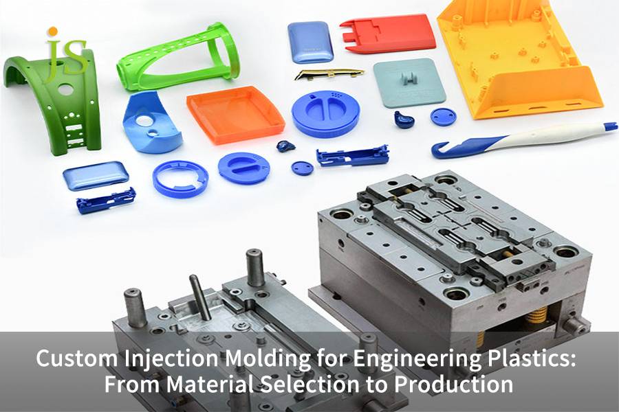

Engineering plastic injection molding transforms high-performance thermoplastic materials (modified PA66, POM, PC) into precision industrial components with a tolerance of ± 0.05mm, eliminating voids and shrinkage marks.
This technique resolves the issue that mass production of high-strength, dimensionally-stable parts is challenging by combining the material shrinkage, hardened steel molds (≥52 HRC) with closed-loop process control.
Engineering Plastics Injection Molding Quick Reference
|
Decision Dimension / Material |
Key Technical Parameters |
Recommended Mold Steel (HRC) |
JS Precision Support |
|---|---|---|---|
|
PA66 (GF Reinforced) |
Dry at 80°C for 4h; vent depth ≤0.01mm |
H13 (52-54) |
Integrated desiccant drying + flow analysis |
|
POM (Acetal) |
Crystallinity shrinkage up to 2.0%, vent depth 0.015mm |
S136 (Mirror polished) |
Shrinkage compensation + cavity sizing |
|
PC (High-Impact) |
High viscosity, shear sensitive; mold temp 80-120°C |
NAK80 / S136 |
Shear heat control + stress relief design |
Key Findings
- Hardness Match of Molds: Glass fiber reinforced injection plastics require mold cavities of hard steel such as H13/S136 (≥52 HRC) because of the high shear forces of glass fibers that result in severe cutting wear of tools.
- Physical Adjustment: Mold dimensions have to be adjusted precisely per resin shrinkage due to crystallization, and multi-stage pressure holding switching has to be adopted to minimize shrink voids.
- Controlling the Flow: Venting is only 0.01-0.015mm deep. Gate and runner are balanced via runner system balancing and mold flow analysis is done.
Why Rely on JS Precision’s Custom Injection Molding Services?
Through our group experience and knowledge from the 15 years of engineering plastic injection molding, one should know that really good custom injection molding service suppliers are those that trace three-dimensional engineering data (material pretreatment, mold steel selection, and process closed-loop), on top of relying upon experience-based trial and error method.
For instance, in the pump housing development project for industrial water treatment using PA66-GF30, it was observed that the porosity of the material after the injection molding was 8.2% without pretreatment with drying. The tensile strength was also 32% lower than the theoretical value in this case.
ISO 9001:2015, Quality Management System, mentions clearly: Establish a traceable parameter recording mechanism for the injection molded components mass production process and retain key process data and procedures until the end of the product lifecycle.
To fulfill the requirement of the standard, we carry out the anisotropical shrinkage simulation and material moisture content testing before the mold is even opened, per project, to eliminate potential mass production deviations. This process is now a part of the delivery database for JS Precision 180+ engineering plastics projects.
Download the Engineering Plastics Injection Molding Material Pretreatment and Mold Selection Guide to understand drying parameters, mold steel matching rules, and to assess the feasibility of your custom injection molding service in advance.
How to Evaluate Physical Properties for Material Selection for Injection Molding?
Material selection for injection molding should prioritize evaluating tensile strength, creep resistance, heat distortion temperature (HDT), and anisotropic shrinkage rate to match the working requirements of high load industrial parts. It should be understood that one material may not work equally well with another even if they are put into the same working condition, failure to make the right choice often means the need to repeatedly replace parts and other expensive problems.
Dimensions for Core Performance Evaluation
- PA66-GF30: Check ASTM D638 tensile strength first (≥180MPa) then ASTM D648 heat distortion temperature (≥250℃) to confirm. Glass fiber is known to cause anisotropic shrinkage which will only give about 1/3 of shrinking rate in the flow direction compared to the horizontal direction.
- POM: Focus on the material's inherent low friction and resistance to wear. The wear volume after prolonged rubbing should be ≤0.1mm³/N·m. Owing to its very high level of crystallinity, the mold has to be designed so that allows for about 2.0% shrinking.
- PC: The main points for this polymer would be its ability to absorb a major amount of impact energy and also how it reacts to shear forces. It should have a heat distortion temperature of at least ≥125℃ when loaded to 1.85MPa. Thin-walled areas of PC are susceptible to shear overheating that results in degradation, this is why injecting speed has to be carefully controlled to PC.
Risk Control in Material Pretreatment:
The lack of sufficiently drying the material will lead to PA66 hydrolyzed and PC shearing scorching. JS Precision employs a vacuum drying dehumidifier to PA66 drying at 80℃, for over 4 hours continuously, resulting in dew point ≤-40℃, and raw material moisture content was maintained strictly below 0.05%. The tensile strength of a part made with PA66 that had not been dried enough will fall by over 30% after injection molding.
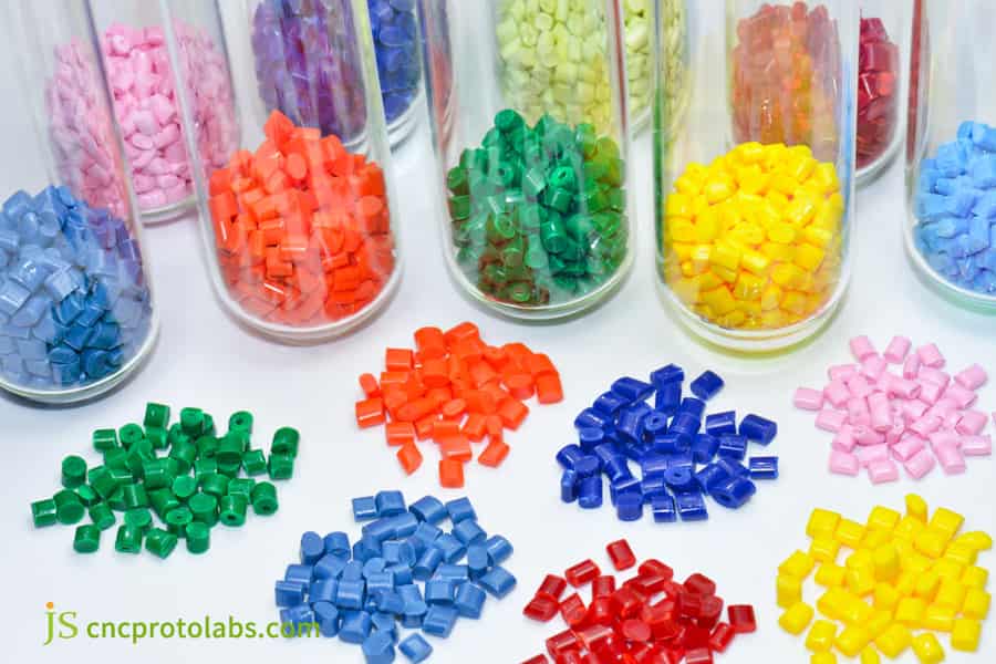
Figure 1: Various colored engineering plastic pellets in test tubes.
How to Prevent Shrinkage and Warpage for High Strength Plastic Parts?
Avoiding deformation of high strength plastic parts starts from the design phase by ensuring uniform wall thickness, avoiding sharp corners and providing rounded edges, and compensating the mold dimensions based on crystallization shrinkage law. The root causes of shrinkage and warpage can be eliminated from design itself. Though, in practical cases, even if the wall thickness varies by more than 25%, one can adjust the process parameters to a lesser effect only.
Physical Causes of Shrinkage and Warpage:
A sudden change of wall thickness will freeze first the surface layer whereas the core will still be able to shrink leading to tensile stresses. Wall thickness deviations exceeding 15% could expose a given location to shrinking by almost 80%.
Three Quantitative Control Rules
Engineering plastic molding service requires three quantitative controls from the design end:
- Mold Cavity Compensation Calculation:
Mold cavity size is determined by the formula Dm = Dp (1 + S) + Dp×S². (Dm - mold cavity dimension. Dp - the part's desired size. S - the material's actual shrinkage rate). Also, consider fiber reinforcement which is a source of anisotropy. For semi-crystalline polymers such as POM an extra 0.3-0.5% is usually added for shrinking compensation.
- Rib Wall Thickness Ratio:
To prevent thick spot that will lead to sink marks and warping the rib floor should not exceed 60% of the main wall connected thickness. In general, the rib height should be 3 times of the wall thickness. Too much height will result difficult filling.
- Gate Shear and Pressure Balance:
Carrying out a runner L/T ratio is the starting point when it comes to Moldflow. Then gates should be arranged so that the pressure is distributed evenly. To achieve the pressure balance by gate freezing time adjustment as well consider hold at least equal pressure distribution after the gate is frozen. If the L/T ratio is over 100:1 you may need more gates.
Fundamentally this means that molds are no longer simply part dimensions-based and it is necessary to make an additional rectangular compensation to the design to allow for glass fiber deviations. Without such an allowance, glass fiber plastic parts with thick walls inevitably shrink.
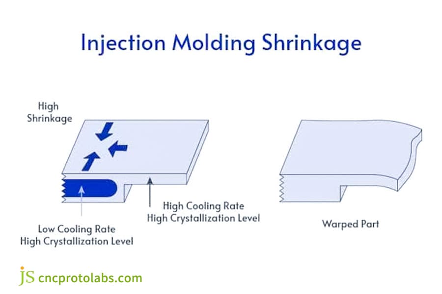
Figure 2: Diagram showing injection molding shrinkage.
What are the Non-Negotiable DFM Guidelines for Custom Plastic Component Design?
The custom plastic component design must fully comply with the draft angle, rib thickness ratio, and corner radius specifications on the quantitative standards to guarantee smooth unmolding and structural strength without causing mass production defects. Breaking these standards is the leading mold rework reason.
General DFM Physical Baselines:
- Draft Angle: a minimum of 1°-2° for inner holes and outer surfaces. 1° for every 10μm of depth in case of textures - to keep ejection scratches under control. To be on the safer side, for the deep cavities (>30mm), the draft angle should be no less than 1.5°.
- Stress Relief by Corner Rounding: sharp edges are banned in right angles. The inner corner radius R and main wall thickness T must satisfy R/T≥0.25 to prevent cracks under stress. For glass fiber reinforced materials, it is recommended R/T≥0.4.
- Uniform Wall Thickness: Wall thickness drastic changes should be limited 15%. Areas to be thick should be hollowed and reinforced to avoid thermal center shift. Set up a gradual transition zone if the difference in wall thickness adjacent sections is more than 0.5mm.
JS Precision Pre-Mold Opening DFM Checklist:
A design team review will cover draft angle, parting surface, ejector pin positions, and weld line predictions, that can anticipate 98% of potential design defects. For DFM analysis, we combine SolidWorks plus Moldflow.
Upload your 3D drawings to obtain a free custom plastic component design DFM compliance review report and identify potential design problems in advance.
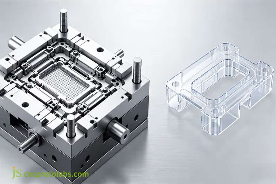
Figure 3: Transparent plastic parts and injection mold.
How to Achieve Precise Tolerances with Custom Injection Molding Service?
To achieve ultra-precise tolerances of ±0.05mm with custom injection molding service (±0.02mm at local mating positions), it helps to coordinate and control mold processing accuracy, mold temperature stability, and multi-stage injection pressure parameters. These elements are all interdependent, missing out control of any one leads to dimensional deviations.
Ultra-precision mold processing control:
Mold cavities are machined using a combination of slow wire EDM and mirror EDM, with the tolerance maintained at ±0.005mm. For mold materials, hardened steel at least 52 HRC is selected so that mold deformation due to high pressure is prevented. Mold insert clearances of less than 0.01mm are maintained to suppress flash.
Mold temperature and injection closed-loop control:
- Mold temperature closed-loop:
An automatic oil temperature heater is employed which keeps the temperature difference between the runner and cavity at a minimal ±1℃, guaranteeing the shrinkage rates are the same and that crystalline materials like POM are well balanced. When the mold temperature fluctuation passes ±2℃, the dimensional of crystalline material could be as much as 0.05mm.
- Injection pressure holding closed-loop:
A high-sensitivity cavity pressure sensor is mounted on the pressure-holding closed-loop injection molding machine. The pressure holding will change in microseconds when the melt is hardening to get rid of any differences in thermal shrinkage volume. The precision pressure holding switching point will have a direct effect on shrinkage and warpage.
ISO 20457:2018 (Tolerances for Molded Plastic Parts): Glass fiber filled engineering plastic molded parts shall match the dimensional range through tolerances, anisotropic shrinkage is to be compensated by 0.01 to 0.02 mm additional tolerance.
We carry out first sample precise adjustments based on this norm so that the delivery accuracy is guaranteed.
Contact our engineers for free mold flow analysis and assessment to verify the tolerance feasibility of your custom injection molding service.
How to Prevent Tool Wear and Corrosion in Engineering Plastics Injection Molding?
Glass fiber and flame retardants give off acid vapors in plastic injection molding, which lead to mechanical wear and chemical corrosion of the mold. The use of highly-hardened alloy steel combined with surface treatment is essential to prolong the life of the mold. The longevity of the mold is a direct reflection on the cost of producing the item.
Mold Wear and Corrosion Mechanisms
When glass fiber is exposed to intense shearing forces, it abrades the mold cavity and functions like sandpaper. Flame retardants also discharge acid vapors such as HCl when heated to high temperatures, leading the steel surface to corrode. Ordinary P20 steel (HRC30) develops flash after 100,000 mold cycles. Fiberglass parts are even less durable, as they reach the limit faster. The gate area is the point of failure, and wear results in a flash thickness of up to 0.05 mm in worn parts.
Mold Steel Selection and Surface Treatment Solutions
|
Steel Grade |
Hardness (HRC) |
Wear Life (cycles) |
Corrosion Resistance |
|---|---|---|---|
|
P20 |
28-32 |
<100k |
Poor |
|
H13 (Quenched) |
52-54 |
~300k |
Medium |
|
S136 (Polished) |
52-54 |
~500k |
High |
|
S136 + PVD |
54-56 |
>800k |
Excellent |
We compared results of tracking data from 800,000 production cycles. It turns out that the gate erosion of the S136 + PVD coated steel is only one-seventh of the erosion of the uncoated H13 steel. This saves you around $12,000 secondary mold opening cost per mold set. So S136+PVD configuration is very important for large-volume engineering plastics molding service.
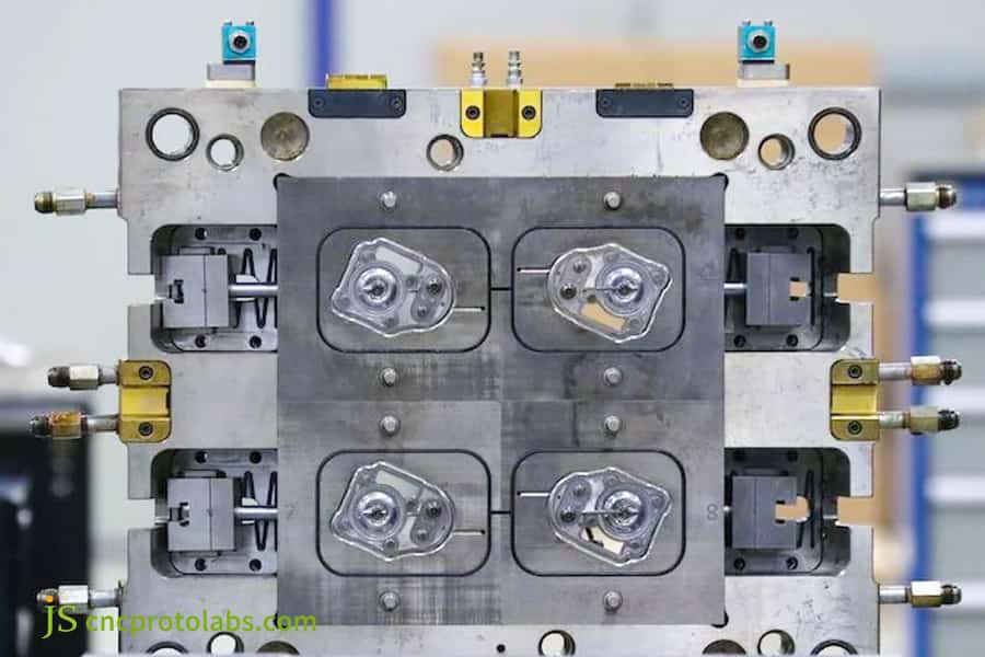
Figure 4: Stainless steel injection mold in factory.
How to Calculate Mold Cavities and Clamping Force for High Volume Injection Production?
The decision of how many cavities and the required tonnage for a high volume injection production should be made by ROI calculation that considers the factors of projected area, cavity pressure, and annual production quantity thereby initial investment costs to be balanced at one side and unit cost of produced items at the other. Incorrect cavity selection means the only result will be idle molds or not being enough to produce.
Logic for Mold Clamping Force Calculation:
Required mold clamping force = Projected area of part (cm²) × injection pressure (35-50MPa for engineering plastics averaged inside the cavity)
This is a formula including a 15% safety factor to prevent flash. With glass fiber reinforced materials, using the upper limit (higher pressure) is recommended because their higher melt viscosity.
Cavity ROI and Break-Even Analysis
Unit cost formula: Unit Cost = Mold Cost / Total Volume + Single Shot Cost. Comparing the break-even points for different cavity numbers:
|
Cavity Count |
Initial Mold Cost ($) |
Unit Cost ($) |
Breakeven Annual Volume (pcs) |
|---|---|---|---|
|
1-Cavity |
3,000 |
1.20 |
- |
|
2-Cavity |
4,800 |
0.75 |
50,000 |
|
4-Cavity |
8,500 |
0.48 |
80,000 |
Example of Mold Closure Tonnage Calculation
Taking a projected area of 200 cm² and an internal cavity pressure of 45 MPa as an example, the required tonnage = 200 × 45 / 1000 × 1.15 ≈ 10.4 tons. A machine of 120 tonnes is actually chosen. The tonnage selection for high volume injection production needs to reserve a 15% safety margin, while considering the ejection stroke and mold size.
JS Precision Case Study: Eliminating Weld Lines and Porosity in Custom Nylon Pump Housings
A well-known industrial water treatment equipment manufacturer came across a production issue of mass producing 30% glass fiber-reinforced PA66 pump housing. The previous supplier's products constantly failed at the weld lines under pressure, and a large portion of the material was found to have internal porosity. Such problems resulted in a 22% scrap rate and the serious delay in the delivery of the whole machine. The customer had failed in the switching of suppliers three times.
Difficulties of the customer and analysis of the problem
- Problem: the weld lines of the PA66-GF30 pump housing failed under pressure, dense internal porosity appeared, and the scrap rate reached as high as 22%.
- Root cause: only a single direct sprue on one side of the cavity, resulting in a slow melt front and weak pressure at the convergence, which caused poor weld line strength, bad exhaust system that let the gas being trapped, which in turn caused the porosity. Mold flow analysis indicated that the temperature in the weld line region was 35℃ lower than the main material temperature.
JS Precision's Solution
To overcome these weld line and porosity challenges in your custom engineering plastic parts, we introduced this methods:
- Gate Location Optimization: Gate was changed from a single-sided direct gate to the central circular gate based on fluid filling simulation resulting in balanced runner convergence point. As a result, weld line position was shifted to a stress-free area.
- Exhaust System Design: The last meeting point of the weld line was machined with a 0.01 mm deep, 4 mm wide exhaust groove. Also, a vacuum ejector pin was used for evacuation aid. After the modification, cavity pressure dropped to less than 10 mbar.
- Mold Temperature Holding Pressure: The mold oil temperature was upgraded to a higher level and the temperature was kept constant at 95℃. The multistage holding pressure change allowed for the alternated distribution of glass fibers and prevented resin collecting area at the weld line.
Lessons Learned:
The first trial only tackled weld lines by raising the injection speed which unfortunately, caused the material to get locally charred. Realizing this mistake straightaway, the team made a reversal of the solution by decreasing the local shear rate and in turn raising the hot runner system temperature and mold temperature, and the issue was solved in a perfect way. This lesson highlights the point that weld line issues are a complex matter than a speed-up remedy.
Final Results
- 45% stronger structural property at the welding part.
- Batch error rate goes below 0.2%.
- Delivery time is shortened by 15 days.
Customer's comments: JS Precision is not a mere processing plant, they comprehend deep engineering. DFM optimization saved us hundreds of thousands in mold modification cost.
To obtain similar pump housing DFM optimization solutions and trial molding reports, upload your drawings to JS Precision and receive a free evaluation and custom engineering plastic parts quote within 24 hours.
Why Choose JS Precision as Your Partner for Precision Engineering Plastics Injection Molding?
If you pick JS Precision, you will benefit from using high quality ISO 9001 certified machining machines, getting help in every phase of mold flow technology, and having high level strict quality control to enhance the value through the whole design and mass production process. We don't merely accept orders and execute them, we are involved at each important stage of product development.
20 years of Engineering Experience and 5,000+ Case Studies
We work with all types of engineering thermoplastics including PA66 PC POM, and PEI. Our records show that our products have very thin wall of 0.8 mm to very high wall up 10mm of hollowed-out walls.
The advantage of our engineering plastics injection molding is that we have been exposed to many failures, we have accumulated a database of more than 300 possible failure modes so that we can detect problems very early in the design phase. An example is for glass fiber reinforced materials, the system will automatically check for fiber detachment risk and warn wall thickness adjustment if necessary.
Testing Facilities and Standards of Delivery
- Certified ISO 9001:2015, complete inspection report provided for every unit.
- Zeiss coordinate measuring machine, factory wall thickness tolerances ±0.01 mm, uniformity deviation <3%.
- Free DFM + Moldflow offered with the quotation, including recommendations for design adjustments and design risk warnings.
Our delivery standard of passing trial molding at the first go for custom injection molding service goes beyond just saying it can be molded. Our historical data shows that the first trial pass rate of molds that have undergone complete DFM and mold flow analysis is 92%, far higher than the industry average of 65%.
FAQs
Q1: Why must PA66 (Nylon) undergo strict drying pretreatment before engineering plastics injection molding?
PA66 (Nylon) is an extremely polarized semi-crystalline thermoplastic. When exposed to moisture content over 0.2%, the injection of the molding under high-temperature conditions would lead to hydrolysis that creates pores as well as silver striations. It also causes the tensile strength of plastic to drop by above 30%. JS Precision conducts vacuum-drying at 80 degrees Celsius for 4 h, reaches a dew point of -40 degrees Celsius & moisture level is maintained below 0.05%.
Q2: What tolerance levels can your custom injection molding service guarantee for engineering plastic components?
The precision of CNC machining tool and wire EDM are at a level of mold accuracy of +/- 0.005 mm. It is complemented by the closed-loop injection molding machine. The finished product's size deviation is kept to ±0.02 to ±0.05 mm stably. With the first sample comes a Zeiss coordinate measuring machine report.
Q3: How do glass-fiber (GF) reinforced engineering resins affect the service life of injection mold tooling?
Since the glass fiber which gets mixed in the molding material has a very high hardness, it should abrade/scratch the mold cavity, in eroded areas. JS Precision for large-volume production of components made partially with glass fiber uses H13/S136 steel materials with hardness levels of at least 52HRC. Easily worn sliders are PVD-coated, making a mold service life of 500,000-1,000,000 cycles.
Q4: What wall thickness specifications should be followed in custom plastic component design to eliminate shrink marks?
Wall thickness of 1.5 to 3.5 mm is advised. Sudden wall thickness changes should be limited to 15% maximum. If a design wants to avoid thick walls due to shrinking, one good solution is to have ribs. Ribs root wall thickness shouldn't be over 0.6 of the main wall thickness. JS Precision offers free DFM (Design for Manufacturing) service for optimization of such defects.
Q5: What are the main factors of cost-saving that you should be concerned over for high volume injection production?
The unit cost changes with the number of cavities, the runner that has been selected, and the molding cycle. The molds with several cavities cost much more in the beginning but, on the contrary, they are much more economical in per-unit processing costs. JS Precision shortens cycle time by mold flow simulation and water channel design. As a result, it reaches the optimum break-even point with robot part handling.
Q6: How does JS Precision achieve mold venting control in precision molds to prevent part burning and voids?
We design different venting grooves for different materials: We select a venting groove depth 0.01mm for PA66 to avoid the overflow and the venting groove depth for PC is chosen as 0.02 mm. We are also using a multi-sectional and micrometer-level venting system to ensure gas rapid and stable release during production of high number of products.
Q7: What must I do to get a precise quotation on custom injection molding from JS Precision?
Send us your 3D drawings in either STP/STEP/IGS formats, your material specs including type of material and grade of material, and other specifications such as annual production volume, and tolerance range. Then we will prepare for you a layered quotation within 12-24 hrs.
Q8: What methods can JS Precision use for traceable check and physical verification of high-performance polymer resins?
Only purchase from legitimate agents such as BASF, DuPont, Bayer, etc. Upon entering the factory, request a COA certificate and use a physical property tester and moisture analyzer for sampling, completely eliminating secondary recycling of materials. You can directly upload the drawings to obtain a quotation, and JS Precision will respond quickly.
Summary
To overcome the difficulties in mass production of high-performance engineering plastics through injection molding, it is necessary to rely on rigorous material science research, accurate shrinkage compensation, optimized DFM geometric parameters, and selection of quenching mold steel that matches high shear conditions. The engineering details described in this guide are the necessary path to creating high-quality, high stability precision plastic parts.
Do you want to be ready for mass production? Upload your 3D files (STEP/IGS) to JS Precision. Our ISO 9001 certified factory team at our Dongguan factory will give you a complimentary DFM and Moldflow report that would make sure the finest mass production solution is found within 24 hours.

Disclaimer
The contents of this page are for informational purposes only. For JS Precision Services, there are no representations or warranties, express or implied, as to the accuracy, completeness, or validity of the information. It is the buyer's responsibility to identify specific technical requirements and request a formal parts quotation. Please contact us for more information.
JS Precision Team
Custom manufacturing solutions. With over 15 years of experience serving more than 1,000 customers, we specialize in high-precision CNC machining, sheet metal fabrication, 3D printing, injection molding, and metal stamping. Having successfully delivered over 300,000 precision parts, we maintain a 99.2% on-time delivery rate across all custom projects.
Our facility is equipped with over 100 state-of-the-art 5-axis machining centers and is ISO 9001:2015 certified. We deliver fast, efficient, and high-quality manufacturing solutions to B2B clients across 150 countries. Whether you require low-volume prototyping or large-scale customization, we support your project with lead times as short as 24 hours. Choose JS Precision for unparalleled efficiency, quality, and professionalism.
To learn more or submit your RFQ, visit our website: www.cncprotolabs.com
Resource

