 English



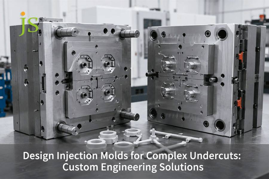

Complex undercut mold design still remains the top difficult areas in injection mold engineering. In fact, each undercut feature increases mold cost by 15%-40% and extends lead time by 2-4 weeks. On the contrary, the most undercut problems that are found during DFM reviews are due to failure of early-stage CAD intervention.
This guide, by JS Precision, distills real project experience in the automotive, medical, and industrial fields and presents a complete engineering way from undercut classification to solution selection and DFM verification.In order for you to be able to use the engineering decision tools related to your investment you can continue reading here.
A Quick Overview of the Core Parameters of Complex Undercut Mold Design
|
Assessment Dimension |
Key Data & Conclusion |
|---|---|
|
Undercut Cost Impact |
Single undercut adds $2,000-$15,000 to mold cost, 15%-40% increase |
|
Depth Classification |
Tier 1 (depth-dia ratio <0.25): simple side-pull. Tier 2 (0.25-0.5): lifter or collapsible core. Tier 3 (>0.5): unscrewing or multi-stage ejection. |
|
Side Slide Limit |
Effective for external undercuts ≤6mm depth, beyond that consider lifter or collapsible core. |
|
Collapsible Core Limit |
Handles internal undercuts ≤20mm depth, suitable for inaccessible internal geometries. |
|
Unscrewing Cost |
Thread unscrewing mechanism costs $2,000-$5,000 |
Key conclusions
- You can lower the costs of molds by 30%-50% if you quickly discover and make the best use of the undercuts parts design during the DFM stage of the project.
- Side slider depth should not exceed 6mm, and core collapse depth should not exceed 20mm. If these values are surpassed, a specialty solution is needed.
- To avoid trial mold failures caused by a lack of stroke, the slider stroke should be determined with the equation Travel=D1.5+3 mm.
- Materials which shrink less are best for undercuting features (e.g. POM PBT). If a material shrinks a lot, one needs to increase draft angles and also recalculate release forces.
Why Trust JS Precision’s Injection Mold Tooling Service for Under-Cut Release Mechanism Design?
With more than 15 years of working hands-on with injection molding for the automotive and medical sectors, our team feels that a real end-to-end injection mold tooling service capable of addressing the challenge of complicated undercut mold design should have three abilities: precise undercut categorization, calculation of mechanism stroke based on volume, and early DFM participation.
In researching through the data of several months of manufacturing process testings, we discovered that more than 60% of undercut mold trial failures resulted from inexact stroke calculation or wrong mechanism choice. It was the main issue that the team faced during the real working time.
ISO 20457:2018, Plastic articles, Tolerances and acceptance of injection molded parts, clearly states that linear dimensional tolerances for precision injection molded parts should be intimately matched to the limits of a dimensional range, and the parting line interference fit should be included in the acceptance parameters.
To comply with this, we imposed the depth-to-diameter ratio by the grading standard, as well as the Travel calculation formula = D×1.5 + 3 mm on every undercut mold project.
In one automotive sensor housing project, based on the mold trial customer's previous was failed by the lack of side slider stroke (only 5mm, while 9.75mm was the actual requirement), a loss of $18,000 and a 6-week lead time occurred. Through the DFM review, we redesigned the mold by raising the stroke to 10mm and transforming the internal undercut into a 6-lobed collapsible core. The trial was successful on the first go, and the scrap rate was reduced from 8.5% to 0.3%.
Want to assess the risks of your undercut mold design? Contact our engineer to obtain the Undercut Mold Design Self-Checklist, covering stroke calculations, mechanism selection, and material matching.
What Is Complex Undercut Mold Design and Why Does It Determine Mold Success?
Complex undercut mold design is a type of challenge in the injection molding where certain features prevent the straightforward removal of the product through the mold opening direction. Typically, these features are side holes threads snaps, internal grooves, and barbs. Their presence directly impacts the possibility of the mold ejecting the product without damage.
Undercut Means Mechanical Interference
- The main fact: An undercut is not a matter of a visual flaw but a mechanical one. Typically, a two-plate mold opens by separating the two halves and the ejector pins push the part out of the core. Still, if there are any protrusions, recesses, or holes perpendicular to the opening direction, these features act as locks, preventing the part from being separated from the mold steel.
- Result of Ejection Force: If you try to eject by force the part when an undercut is present, the part will be damaged, the mold will be broken, or both.
- Technical explanation: The first step injection mold tooling service is to recognize the mechanical aspect of undercuts, they represent the mechanical locking between the part and the mold.
Overview of Four Popular Demolding Mechanisms
- Side-Action Slides: Works for external undercuts, maximum effective depth 6mm.
- Angled Ejectors: Works for internal undercuts, tilt angle 5°-15°.
- Collapsible Cores: Works for internal undercut depth up to ≤20mm, segmented shrinkage release.
- Thread Removal Mechanisms: Works for threaded features, the price is 2,000-5,000.
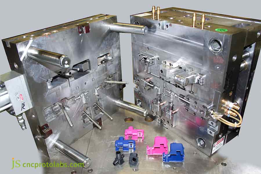
Figure 1: Open injection mold with complex side-action slides and precision components.
How Do Side-Action Slides Solve External Undercut Ejection Problems?
Side-action slides are the most frequently chosen method for dealing with external undercuts in molds. A sliding component fixed on the side of the mold withdraws horizontally at right angles to the opening direction of the mold, at the mold opening edge, removing the undercut shape. It is a good way to handle external undercuts of depth 6mm.
Side-Action Slide Working Principle
- Closing Phase: During mold closing, the slide is directed into the mold cavity position by the angled guide pin,creating the undercut feature.
- Mold Opening Stage: Once the injection molding is finished and the part is sufficiently cool, the mold starts opening. The angled guide pin causes the slider to move backward horizontally along the groove, so the undercut is exposed before the ejector pin pushes the piece out.
- Stroke Calculation: For every 1mm of undercut depth on each side of the slider, there will be a 3mm safety margin. To calculate the total amount of stroke travel, the formula is: Travel = D×1.5 + 3 mm.
Three Major Design Considerations:
- Space Requirements: Undercuts should be positioned on the external side of the component, with enough room left for the slider to fully retract. First and foremost, the external space around the mold must be identified when considering undercut injection molding options.
- Draft Angle Design: Design the draft angles on all internal surfaces of the part in the direction of the slider movement to ensure the slider can be retracted smoothly without part damage. Supply molds side slider injection tooling design for complex parts undergo a trade-off between draft angle and stroke matching.
- Cost Impact: Every additional side slider feature adds 15%-20% to the mold cost. Basically side-slider slides, being a preferred option for external undercuts, demand an accurate stroke calculation, any close enough estimate will result in trial molding failure.
Download the Side-Action Slide Design Parameter Table, which includes a stroke calculation template and recommended draft angle values to help you quickly verify your design.
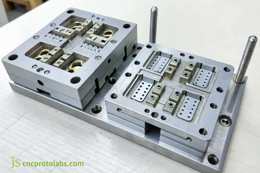
Figure 2: Stainless steel mold components with cylindrical cavities and precision rods.
What Is the Core Difference Between Angled Lifters and Side-Action Slides?
What sets Angled Lifters and side-slider slides apart is the direction they move in. When the mold opens and ejector plate advances, angled lifters not only go up and down but also incline, which is why the undercut can be released from the inside out. That is why angled lifters are used for internal undercuts (for example: internal wall snaps, internal protrusions) whereas side-slider slides are used for external undercuts.
Operation and Drawbacks of Angled Lifters
- Movement Mechanism: Angled lifters are fixed onto the ejector plate. When the mold is opened and the ejector plate is pushed forward to eject the part, the angled lifter together with the ejector plate moves and slides inside or outside along the inclined guide groove, thereby releasing the internal undercut at the dismantling.
- Major Benefits: This does not require any extra hydraulic or pneumatic drive, the release of the undercut is done simply by the mechanical operation of the mold opening.
- Technological Drawbacks: Typically, the tilt angle ranges between 5° and 15°. If it is increased, this will cause a sharp increase in the friction during the sliding and rapid wear of the components. So, complex mold tooling solutions must be designed within this range.
Side-Action Slide vs. Angled Lifter Comparison Table
|
Comparison Dimension |
Side-Action Slide |
Angled Lifter |
|---|---|---|
|
Applicable Position |
External undercuts |
Internal undercuts |
|
Motion Direction |
Horizontal, perpendicular to mold opening |
Combined vertical + angled motion |
|
Drive Method |
Angle pin / hydraulic cylinder |
Ejector plate mechanical motion |
|
Depth Limit |
≤6mm |
≤6mm (beyond this use collapsible core) |
|
Angle Limit |
10°-25° angle pin angle |
5°-15° lifter angle |
|
Cost Impact |
+15%-20% per slide |
+10%-15% per lifter |
DFM mold tooling service requires ensuring the draft angle is not less than 5° during selection, otherwise, it may lead to scratches, jamming, and premature wear of the mold mechanism.
How Do Collapsible Cores Handle Internal Undercuts Deeper Than 6 mm?
Collapsible cores, which radially contract inwardly during ejection, release internal undercuts and deal with undercuts up to 20mm in depth. When lateral access is not possible and the depth of the undercut is more than 6mm, collapsible cores are usually the solution of choice.
Collapsible Core Working Principle
- Molding Stage:
A collapsible core is composed of core petals with segments that are capable of being moved and are fitted around a central conical mandrel. In injection molding process, with the support of the mandrel, the petals together make a complete cylindrical or irregular shape of the core and mold the internal undercut features.
- Ejection Stage:
At first, the central mandrel is pulled in the opposite direction. When the petals are contract inwards by the force of springs or by machinery. The outer diameter of the core that is radially reduced is less than the inner diameter of the undercut, i.e. the part can be removed smoothly.
- Core Technical Parameters:
The typical number of segments is 4-12. If there are more petals, there will be a higher shrinkage, but also a more complicated structure. A complex undercut mold design should strike a balance between these factors.
Collapsible core design considerations:
- Shrinkage stroke: It should be more than the depth of the undercut.
- Applicable diameter: Normally collapsible cores are good for pipe fittings with diameters of less than 90mm, bigger diameters will need a special design.
- Material selection: Low-shrinkage materials such as POM and PBT should be used so that the dimensions do not change. Injection mold design optimization in collapsible core solutions should consider the number of flaps relative to the amount of shrinkage.
- Maintenance cost: The maintenance cost for collapsible cores is typically 30%-50% higher than that for side-sliding cores due to replacement of flaps or re-grinding surfaces being necessary regularly.
To sum it up, collapsible cores are the only viable solution if one wants to work with deep internal undercuts, but they do come at the cost of more maintenance investment.
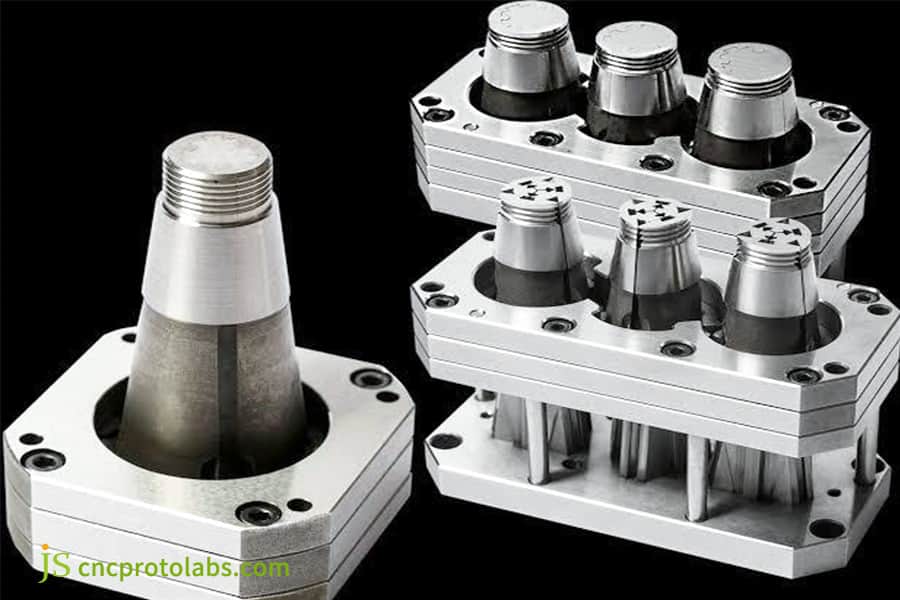
Figure 3: Metallic collapsible cores for internal undercut molding applications.
What Are the Design Principles and Cost Components of Unscrewing Molds?
Unscrewing molds convert the motion of the injection molding machine when the mold is opened to the exact rotational motion of the core, thereby allowing automatic thread removal. The typical cost of a thread unscrewing mechanism is from $2,000 to $5 000 which is actually the highest of the four alternatives, but it is at the same time the most dependable one with thread quality.
Unscrewing Mold Working Principle
- Transmission Method: Transmission methods that are typically employed include gear-rack mechanisms, hydraulic motors, and servo motor drives. Thread precision requirements determine the transmission method for custom injection mold design service.
- Action timing: The core begins to rotate (usually 720° to complete complete complete thread disengagement), while the core gradually retracts backwards to reduce wear between metals.
- Multi-Cavity Applications: Using multi-cavity molds, the idea of using 1-96 cavity unscrewing can be realized, but the mechanism to be built becomes more and more complicated with each new thread feature.
Three Major Design Challenges
- Exact Computation of the Transmission System: The number of rotations must be an exact match to the number of thread teeth.
- Very Close Monitoring of the Motion Timing: The rotation and the retraction actions have to be perfectly synchronized.
- Choice of Materials: The gears and the racks should be of very high strength and highly resistant to wear.
For external threads on small parts that are shallow, a method of manual forced release can be used sometimes in complex mold tooling solutions thereby getting rid of the need for the dedicated unscrewing mechanism.
How to Select the Right Ejection Mechanism Based on Undercut Depth-to-Diameter Ratio?
According to injection mold designers, undercuts can be divided into three levels based on the depth-to-diameter ratio of the feature. Tier 1 (<0.25) refers to the use of simple side-pull or angled guide pins. Tier 2 (0.25-0.5) would need angled ejectors or collapsible cores. Tier 3 (>0.5) would need a screwing or an unscrewing mechanism or a multi-stage ejection system.
Three-level Classification Standard for Undercuts
ISO 294-3:2020 demands: The process conditions of the joint line area and the distance from the gate to the joint line must be controlled parameters for specimen preparation, otherwise, tensile strength data cannot be compared.
To meet this standard, we first use the depth-to-diameter ratio calculation to decide on the selection for each undercut project, forgetting experience as the first step.
| Tier | Depth-Diameter Ratio | Recommended Mechanism | Cost Impact |
| Tier 1 | <0.25 | Simple side-pull, angle pin | +10%-15% |
| Tier 2 | 0.25-0.5 | Lifter, collapsible core | +15%-25% |
| Tier 3 | >0.5 | Unscrewing, multi-stage ejection | +25%-40% |
Five Steps Method for Selection Decision
- Find the undercut place: outside or inside? The very first step in offering undercut injection molding solutions is to know the location.
- Measure depth and diameter: Take precise measurements of the undercut's dimensions.
- Determine the depth-diameter ratio: Apply the formula Ratio=Depth/Diameter to find out the tier as the three-tier classification.
- Recognize the mechanism type: Based on the tier, choose the mechanism that is pre-approved.
- Evaluate the cost effect: The additional cost for two simple undercuts is around 50% that of a single undercut, more than two undercuts raise mold cost by 100%-200%.
Selection decisions for injection mold tooling for complex parts must always be based on data rather than on experience.
Unsure which level your undercut belongs to? Download the Undercut Classification and Selection Decision Table, enter the depth and diameter, and it will automatically match recommended mechanisms.
How Does Material Selection Affect Undercut Ejection Design?
The material shrinkage rate mainly determines the actual gap between the part and the core at undercut demolding, affecting the demolding force and selecting the demolding mechanism indirectly. The low-shrinkage material is the choice, like POM (shrinkage rate 1.5%-2.5%), PBT (1.5%-2.5%) for undercut feature design.
The Influence of Shrinkage Rate on Demolding Force
- Differences of Shrinkage Rate: The maximum difference of the shrinkage rate between different resins is 5 times e.g. for low-shrinkage POM (1.5%-2.5%) vs. high-shrinkage PP (1.5%-3.0%), PA (0.5%-2.5%). Injection mold tooling service have to vary their design parameters per a shrinkage rate.
- Clamping force: the higher shrinkage rate the greater is part clamping force on core after cooling demolding resistance the higher is.
Common Engineering Plastic Shrinkage Rates and Draft Angle Recommendations
|
Material |
Shrinkage Rate |
Recommended Draft Angle (External) |
Recommended Draft Angle (Internal/Undercut) |
|---|---|---|---|
|
POM |
1.5%-2.5% |
1°-2° |
2°-3° |
|
PBT |
1.5%-2.5% |
1°-2° |
2°-3° |
|
PA66 |
0.5%-2.5% |
1°-3° |
3°-5° |
|
PP |
1.5%-3.0% |
2°-3° |
3°-5° |
|
PA66-GF30 |
0.2%-0.7% (anisotropic) |
2°-4° |
4°-6° |
Custom injection mold design service deal with significant anisotropy of shrinkage rates in glass fiber filled materials so such factors should be very carefully handled. Particular caution has to be taken on the effect of fiber orientation on demolding force if undercut demolding is used.
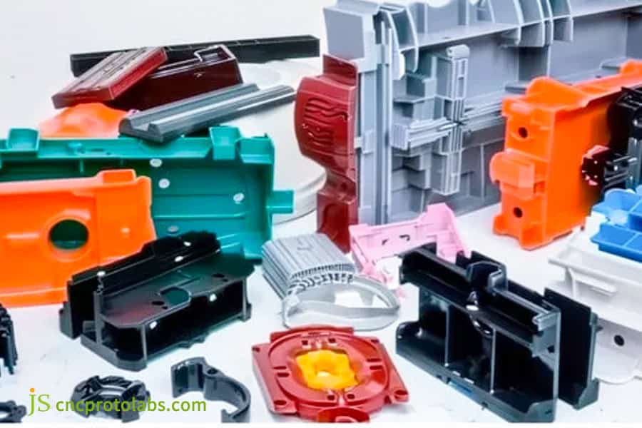
Figure 4: Assorted plastic and metal components including pipes and gears.
How Does JS Precision Eliminate Undercut Risks Through DFM Analysis Before Mold Manufacturing?
JS Precision's DFM mold tooling service spots and removes undercut risks before mold manufacturing with a 4-step undercut checking procedure. The problem of 60+ percent of the undercut issues in DFM reviews could have been prevented if the CAD design had been intervened early on.
DFM Four-step Checking Procedure
- Determination of the Partingline and Ejection Direction: In the 3D CAD model, parting line location and ejection direction of the part must be precisely defined. This is to be taken as a reference in determining all potential undercuts.
- Draft Angle Check: 2° minimum draft angle for external walls and 3° minimum draft angle for internal walls and features with undercuts. For the textured surfaces add draft angle of 1°-2° per 0.025mm of texture depth.
- Review of Undercut Areas One Surface at a Time: Each undercut surface identified by the DFM software leads the engineers to think of three possibilities: Could the undercut be done away with by making the draft angle larger? Can it be removed by changing the parting line? Is the presence of the feature really needed?
- Mechanism Selection for Remaining Undercuts: If an undercut can be deleted by the first three methods above, then plan the mechanism type and number in detail and include these mechanisms in mold cost estimation. If this is not possible, then go on with other undercuts.
DFM Value in Numbers
Lessening the possibility of rework after mold has been produced, a significant decrease in risk, injection mold design optimization is possible by Moldflow filling simulation, leading to a 60+ percent risk reduction. DFM intervention at an early design phase can avoid 30% and up to 50% of mold costs.
How Did JS Precision Solve a Complex Undercut Mold Challenge for an Automotive Sensor Housing?
Customer Difficulties
Earlier the customer had ordered from a different injection molding company the making of this product, but the initial trial molding was unsuccessful. Lack of sufficient travel of the outer sliders made the part stuck within the mold and couldn't be ejected. After a forced ejection, the part's sidewall got torn. Besides losing $18,000 on the mold, the customer also forfeited a 6-week lead time before they approached JS Precision with updated 3D drawings.
JS Precision Solution
- DFM Evaluation
Two principal flaws have been detected-the undercut depth of the outer side hole was 4.5mm, while the slide travel of original mold was merely 5mm. Based on the equation Travel = D×1.5 + 3mm, the necessary travel is 9:75mm, the undercut depth-diameter ratio of the internal groove was 0:42 (Tier 2), and the original design wrongfully used a slanted ejector rather than a collapsible core.
- Design Change
The outer slide travel of 5mm was modified to 10mm (a 0.25mm safety margin was also added). In keeping with that, the length of the slide guide groove was extended. Instead of an internal slanted ejector, a 6-lobed collapsible core was chosen, allowing the central mandrel to travel 12MM and the undercut part of 8MM to come off with no issue.
- Moldflow Validation
It turned out that the shrinkage rate of PA66-GF30 material in the undercut region is 0.5% - 0.7%, which means that the collapse core shrinkage stroke design value has enough margin.
- Steel and Heat Treatment
The Slider and the core flaps of collapsible cores are made of H13 tool steel and quenched into 48 - 50 HRC,the mold life is at least 500,000 cycles.
- Trial Molding And Optimization
The first trial molding turned out quite satisfyingly except for a small delay in the return motion of the collapsible core flaps. This issue was altogether eliminated when a spring return of flaps was changed from a single spring to two springs parallel.
Lessons Learned from Failure:
- The slider stroke calculation must be based precisely on a formula: D x1.5 + 3 mm, any kind of guesswork will cause trial molding to fail.
- Undercut grading shall be based not on a guess (the years of a person) but on a mathematical calculation of depth-to-diameter ratio.
- The direction of glass fibers in PA66-GF30 has great influence on the wearing out of the collapsible core flaps. After 500 trial-molding cycles, very slight traces of wearing were found on the surface of valve segments. The surface of the valve segment was coated with DLC (diamond-like carbon) and that solved the problem.
Final Result
The total mold cost amounted to $42000 (including two undercut mechanisms). The time needed to deliver the mold was 8 weeks. The trial molding was done right on the first attempt and so far, the mold has been running trouble-free in the customer's factory for over 300,000 cycles, thereby cutting down the scrap rate from 8.5% of the original solution to only 0.3%.
The key to successfully implementing complex mold tooling solutions is not so much a miracle-like problem solving but setting up repeatable engineering ways.
Your undercut mold project may also have similar room for optimization. Upload your 3D drawings (STEP/IGS) and receive a free DFM assessment report within 48 hours, including undercut identification, cost estimation, and mechanism recommendations.
Why Choose JS Precision as Your Complex Undercut Mold Design Partner?
By picking JS Precision you will get a team of engineers who are the masters of injection mold. We do not use our experience to make guesses, what matters here is the technical background of the undercut design mold. Through DFM analysis, Moldflow simulation as well as precise engineering calculations, we deliver proven and complex undercut mold design solutions.
Core Competencies
- Engineering Capabilities:
Our team applies a three-level classification system for depth-to-diameter ratio to guide the component selection process. Slider stroke calculation = D×1.5 + 3 mm. Moldflow shrinkage simulation is employed to ensure shrinkage is within limits of the undercut. Tool steel heat treatment is controlled to 1 HRC precision level.
- Service Process:
We deliver free DFM analysis reports, itemized undercut mechanism cost pricing transparently. And our client engineers are fully integrated with our mold design engineers.
- Quality Assurance:
500+ trial moldings verification runs are performed before shipment and we accompany these with the complete trial molding report plus release video clip. Also our mold's service life is guaranteed at least 500,000-1,000,000 cycles.
FAQs
Q1: When can undercuts be completely avoided without special mechanisms?
By shifting the parting line, undercuts can be released from molds as natural demoldable surfaces without having to add extra demolding devices. In some cases of non-functional undercut features, deletion through direct design is also an effective optimizing method which we recommend in our DFM review as one of the low-cost priority changes to carry out.
Q2: Are side-action slides and angled lifters interchangeable features in a mold?
The combination of side-action slides and angled lifters in a mold is quite possible. After mold opening and retraction, side-action slides release the outside undercuts. Meanwhile, angled lifters free the inside undercuts during the ejection phase. We will double-check their operation sequence in the motion simulation to prevent any possibility of mechanism interference.
Q3: Are undercut features more than 6 mm deep definitely side-action slide infeasible?
It is a common practice not to consider side-action slides when designing undercuts deeper than 6 mm. The forced closing would distort the angled guide pins and create demolding resistance. Even with larger components that can be used and increase cost and failure rates, this is still the best alternative than using side-action slides for such features. More dependable and safe is the use of collapsible cores and angled lifters together.
Q4: Maintenance cost-wise, how much of an increase of the collapsible core is over side-action slide?
The collapsible core maintenance cost is about 30%-50% higher if compared to side-action slides. The complicated multi-lobed precision components are highly sensitive to mechanical stress and their performance degrades rapidly resulting in the need for frequent parts repairs, replacement and, of course, grinding. We achieve longer service life through use of high-quality steel and proper heat treatment.
Q5: What are the undercut mold design restrictions caused by materials with glass-fill (e.g. PA66 - GF30)?
Materials that are glass fiber filled are known to result in very different shrinkages along the flow and cross-flow directions. These anisotropes cause a great stress variance to develop on undercut regions after demolding. We use Moldflow simulation analysis of the orientation and distribution of the glass fibers to precisely optimize the mold structure of the undercut and demolding parameters in particular of the undercut zone.
Q6: What is the content and scope of JS Precision's DFM mold tooling service, precisely?
The scope and content of our DFM mold tooling service involve parting line layout, standard draft angle analysis, undercut level review, cost assessment of the mold's mechanical part, and mold flow simulation verification. We go through design mistakes, find out the design issues, and make a professionally written report for our customers in an amazing time within just 3, 5 days from receiving the job.
Q7: Which industries has JS Precision delivered complicated undercut mold projects to successfully?
We have many experience working in automotive medical industrial equipment and consumer electronics industries, we have finished hundreds of sophisticated undercut mold projects, following all the standardized procedures from the DFM design stage until simulation verification and trial mass production stage so we always guarantee the highest level of mold quality and stability right down the line.
Q8: How can I get a quote on a undercut mold tooling from JS Precision?
Get an exact quote by sending us STEP and IGS format 3D models as well as 2D engineering drawings that contain material and annual demand information. We send a detailed DFM report to you that lists the undercut mechanism costs and gives fully open pricing without any covert fees within 5 business days.
Summary
A major factor in making decisions about complex undercut mold design is engineering data, not experience or intuition. Side sliders are recommended for external undercuts up to 6 mm, and collapsible cores for internal ones up to 20 mm. The cost of a thread release mechanism is about 2,000 to 5,000, and early intervention through DFM could save up to 30%-50% of mold costs. Ratio grading standards for depth over diameter, slider stroke calculation formula (Travel = D×1.5 + 3 mm), as well as demolding force impacted by material shrinkage altogether build up a decision-making system that is based on figures and facts for deciding which undercut mold you need.
Upload your part details to JS Precision, and you will get a gratis DFM analysis. JS Precision pinpoints, quantifies, and suggests solutions for each undercut feature before mold production, your next complex undercut mold project is guaranteed to succeed right from the drafting phase.

Disclaimer
The contents of this page are for informational purposes only. For JS Precision Services, there are no representations or warranties, express or implied, as to the accuracy, completeness, or validity of the information. It is the buyer's responsibility to identify specific technical requirements and request a formal parts quotation. Please contact us for more information.
JS Precision Team
ustom manufacturing solutions. With over 15 years of experience serving more than 1,000 customers, we specialize in high-precision CNC machining, sheet metal fabrication, 3D printing, injection molding, and metal stamping. Having successfully delivered over 300,000 precision parts, we maintain a 99.2% on-time delivery rate across all custom projects.
Our facility is equipped with over 100 state-of-the-art 5-axis machining centers and is ISO 9001:2015 certified. We deliver fast, efficient, and high-quality manufacturing solutions to B2B clients across 150 countries. Whether you require low-volume prototyping or large-scale customization, we support your project with lead times as short as 24 hours. Choose JS Precision for unparalleled efficiency, quality, and professionalism.
To learn more or submit your RFQ, visit our website: www.cncprotolabs.com
Resource

