

Custom injection mold builder is a core technology carrier that pushes products from single cavity prototype verification to multi cavity mass production with millions of levels of productivity. This production approach solves the critical issues of mass production that are encountered during this transition, like uneven fill, variations in dimensional tolerance, and the short lifespan of the mold, etc. After a product passes the prototype phase, R&D engineers and procurement managers usually face challenges such as warpage and flash when they move from a single-cavity to multi cavity mold operation.
This article examines how eight manufacturers differ technically in their production and also presents quantitative DFM (Design for Manufacturability) metrics, giving you this main points:
- A fair, side-by-side assessment of the key technical parameters and manufacturing capabilities of eight leading global multi cavity mold manufacturers.
- The basic principles of engineering that mold runner balancing, cavity pressure replication, and cooling channel optimization are based on.
- Practical examples of how manufacturer of the specialized hard-mold correct multi-cavity mold imbalances by detailed DFM and precision machining.
A Quick Overview of Core Capabilities of Global Multi Cavity Mold Manufacturer
| Manufacturer | Core Tooling Service | Max Cavity Scaling Capacity | Steel Hardness Standard |
|---|---|---|---|
| JS Precision | precision mold tooling company | Single cavity to 16/32/64 cavities | H13/S136 (HRC 48-52) |
| Protolabs | injection mold tooling design | Single cavity to 4/8 cavity rapid aluminum/steel mold | Aluminum alloy / P20 (HRC 30-32) |
| Xometry | multi cavity mold manufacturer | Global supply chain flexible cavity expansion | Customer-specified (P20 to H13) |
| Fictiv | plastic injection mold service | Digital DFM-driven multi-cavity mold | NAK80 / S136 (HRC 38-42) |
| RapidDirect | single to multi cavity tooling | Modular quick-change mold base multi-cavity molding | P20 / 718H (HRC 32-34) |
| Star Rapid | high volume mold tooling service | High-temperature high-pressure multi-cavity hard tooling | H13 / 2344 (HRC 48-50) |
| Hubs | custom injection mold builder | Distributed supply chain multi-cavity customization | Subject to specified supplier chain standards |
| WayKen | precision mold tooling company | Precision rapid tooling & multi-cavity modification | P20 / NAK80 (HRC 30-35) |
Key Takeaways
- Cavity multiplication needs clamping force recalculation:
When moving from a single cavity to 16 or 32 cavities, the projected area increases drastically. That means, the injection molding machine tonnage should be aligned to this change to avoid flash defects resulting from lack of clamping force.
- Runner balancing is a must for multi-cavity molds:
To achieve the same filling pressure for each cavity, a perfect balance H-type runner system is usedthis involves a Moldflow shear-heat analysis and the application of the "1.2 x D" cold slug well standard.
- Hardened steel molds should be used for large-scale production:
If the production volume is above 100,000 cycles, then aluminum molds and soft P20 steel are not advisable, instead, heat-treated hardened steels (like H13 or S136) having a hardness of HRC 4852 should be used.
Why Trust JS Precision for Injection Mold Tooling Design and Manufacturing?
JS Precision operates a physical factory and has a leading senior engineering team that can offer technical support for the complete mold production cycle from the prototype stage to mass production.
From our experience in several automotive and medical component projects, the stability of molds is what directly impacts the availability of the production lines, tiny errors in the design alone could bring the loss of hundreds of thousands of production runs.
The international quality management system ISO 9001:2015 has a requirement that "mass production mold deliveries must be accompanied by traceable material certificates and heat treatment verification documents."
Each one of our molds is supplied with an original manufacturer's material certificate, third-party hardness test report, and a full-size CMM inspection report to fully comply with this standard. The core engineering team has 12 members with an average industry experience of 20 years that trusts us to catch more than 90% of mass production risks during the design phase. The long-term stable operation of multi-cavity molds is mainly locked down by a solid quality control system.
You can upload 3D drawings of your parts to receive a free DFM assessment of your injection mold tooling design, allowing you to identify design risks in advance and avoid subsequent mass production losses.
How Do Multi Cavity Mold Manufacturer Teams Avoid Filling Imbalances and Haloing Defects in High Gloss Components?
The secret to multi-cavity imbalance problem is making sure that the melt front reaches the cavity at the same time by adjusting the runner cross-section. If a multi cavity mold manufacturer bases the mold only on geometric symmetry without considering the shear heat, it might bring about halo defects and short shots on the edges of high-gloss parts.
Shear Thinning Effect and Runner Balance Principle
After high-viscosity polymers are injected into the runner at high pressure, high shear rate in the wall surface causes a shear thinning effect as well as thermal stratification. Expert multi cavity mold manufacturer include shear heat compensation in the earliest design stages to prevent cavity filling differences. The industry-standard cold slug well design is like this: the cold slug well diameter is 1.2 x D of the diameter at the end of the main runner, and the depth is 1.5 x D.
In other words, just geometric symmetry will not be enough, there should also be an accurate tuning of the inner diameter resistance of the runner channels to have exactly the same flow and pressure in each cavity.
Comparison of Runner Design Capabilities among Mainstream Manufacturers
The runner design logic of different manufacturers directly determines the filling consistency and yield ceiling of multi-cavity molds.
| Manufacturer | Runner Design Type | Cavity Pressure Coefficient of Variation (Cv) | Applicable Production Volume Range |
|---|---|---|---|
| JS Precision | Fully balanced H-type runner + shear heat compensation | ≤2% | Mass production over 100k shots |
| Fictiv | Digital DFM equal-diameter runner | 3%-5% | Small to medium batch production |
| Xometry | Supply chain standard manifold | 6%-8% | Flexible low-volume production |
| Protolabs | Simplified rapid tooling runner | ≥8% | Prototype validation |
Controlling the runner cross-section diameter adjustment accuracy within 0.02 mm is enough to keep the cavity pressure variation coefficient within 2%. This technical criterion is a key feature of high-end plastic injection mold service. Digital contract platforms mostly present simplified equal diameter runners, where the pressure variation coefficient even goes beyond 8%, this way parts volume shrinkage becomes uneven and shrinkage defects occur.
A mature injection mold tooling design process conducts these standard optimization steps:
- Compute the shear rate differences of each runner with the help of Moldflow simulation.
- Adjust slightly the diameters of the edge runners to counterbalance the decrease in viscosity due to shear heating.
- The cold slug well is designed as per the 1.2 x D norm to ensure the cold slug is captured at the front end.
- Use cavity pressure sensors to find out the real filling consistency during trial molding.
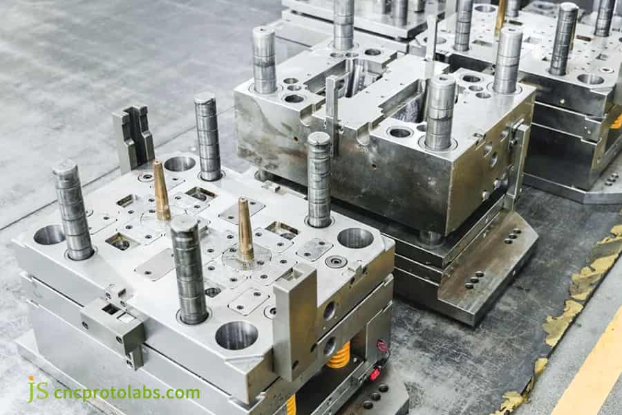
Figure 1: Close-up of a multi-cavity metal injection mold showcasing complex tooling details.
How to Calculate Tonnage in Single to Multi Cavity Tooling Transitions Considering Nominal Wall Thickness Deviations?
When upgrading to a multi-cavity mold, the amount of clamping force required must be determined by adding up the projected areas of all cavities and runners. If you mistakenly use the single-cavity clamping force for single to multi cavity tooling changes, it will cause the mold to bulge, localized collapse, and flash defects.
Core Formula for Clamping Force Calculation
For single to multi cavity tooling updates, the clamping force calculation should strictly follow the standard industry formula given below:
F=(A_{cavities}+A_{runners})P_{inside}1.2
Here, P_{inside} is the average pressure inside the cavity, and 1.2 is a safety factor.
In better words, the clamping force needs to exceed the melt expansion force with an added safety margin for preventing flash and bulging problems.
Differences in Lateral Mechanism Rigidity Design
High volume mold tooling service takes much stiffer lateral mechanisms in the mold than small-batch prototype molds. For example, automated DFM systems like Protolabs suggest that part wall thickness variations should be limited to between 20% and 30% of the nominal wall thickness to prevent dimensional deviations due to uneven cooling. But Hubs which depend on a distributed supply chain, encounter changes in lateral mechanism rigidity standards in their partner factories, resulting in less precise unified control compared to directly-operated physical factories.
Custom injection mold builder, as one of the most dependable, accurately measures clamping force through this standard methods:
- Determine the total projected area of all the cavities.
- Multiply by the average internal pressure of the cavity corresponding to the material.
- Multiply by a safety factor of 1.2 to obtain the final required clamping force.
For multi-cavity high-pressure (above 120 MPa) operations, JS Precision has installed a 25° wedge base for mechanical rigidity pre-tightening of the undercut side slide mechanism to ensure that the slide locking force is not less than 115% of the side expansion force, which is a physical way of eliminating the expansion clearance.
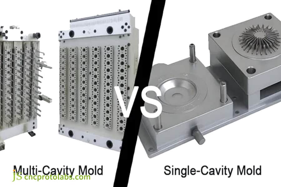
Figure 2: Visual comparison of single-cavity and multi-cavity molds with a split screen layout.
Which Material Selection Rules Help a High Volume Mold Tooling Service Secure Million Shot Lifetime?
High-volume multi-cavity mold cores should be manufactured from high-quality alloy steel that has been through electroslag remelting process. If one resorts to using cheap steel for high volume mold tooling service, the gate is bound to deteriorate due to the erosion by glass fiber very soon.
Comparison of Performance of Mainstream Mold Steels
High-volume mold tooling services impose very tight restrictions on the durability and hardness of the steel. Different steels show fairly large variations in their wear resistance so the choice should be aligned with production volume and material characteristics.
| Steel Grade | Hardness After Heat Treatment | Rated Cycle Life | Application Scenario |
|---|---|---|---|
| S136 (ESR) | HRC 48-52 | Over 1,000,000 shots | High gloss, corrosion resistance, high volume production. |
| H13 | HRC 48-50 | 800,000–1,000,000 shots | General engineering plastics, glass fiber reinforced materials. |
| NAK80 | HRC 38-42 | 300,000–500,000 shots | Medium batch, appearance parts. |
| P20 | HRC 30-34 | 100,000–200,000 shots | Low volume production, prototype validation. |
The Core Impact of Heat Treatment Process
The lower bounds of hardness for high cycle life are not experimentally determined.
It is clearly spelled out in the criteria for hot work die steel listed in the ASTM A681 tool steel standards that "H13 class hot work die steel must be at least HRC 46 after quenching for high cycle fatigue application".
For component containing 30% glass fiber, qualified precision mold tooling company require vacuum quenching followed by three tempering for post. Metallo-graphic hardenesse is be stabilized between HRC 48-52 and network carbides are be dissolved.
For H13/2344, star rapid employs the heat-treatment to be between the hardened hrc 48-50 to be enabling, providing the wear resistance for medium-to-high production. Some prototype producers use pre-hardened steel, without heat-treatment, hardness be only HRC 30-35, very fragile toward the mechanical breakage.
There are several principles can generalize the choice of steel for the professional multi-cavity mold manufacturers, such as:
- For production volumes exceeding 100,000 molds, H13 and higher grade steel are preferred.
- High-gloss transparent parts must use S136 ESR grade steel.
- Glass fiber reinforcement materials require correspondingly higher steel hardness grades.
- High-volume production situations demand vacuum quenching + several tempering cycles.
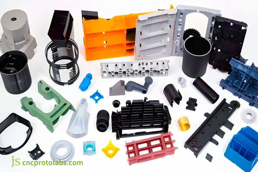
Figure 3: An array of colorful plastic injection molded components demonstrating material versatility.
How Do Conformal Cooling Channels Resolve Temperature Gradient Deviations in Plastic Injection Mold Service Projects?
Basically, the only way to optimize multi-cavity mold cycle time is by having all cavities at a uniform and steady surface temperature. In plastic injection mold service, simply drilling cooling tunnels cannot fix the problem of slow heat removal on the core part. Because of this, conformal cooling channels are the only way to keep temperature changes in control.
Performance differences between traditional cooling and conformal cooling
Around 70-80% of the injection molding cycle time is taken by the cooling stage in plastic injection mold service. Supply chain platforms working in a distributed manner like Hubs usually employ the old-style linear cooling solution by CNC drilling which needs custom conformal cooling channels that come with longer lead times. But, 3D printing (SLM) conformal cooling channels can closely follow the shape of the product allowing for uniform heat removal.
Primary Considerations for Designing Conformal Cooling Channel
Professional mold tooling design guide not only specify how close conformal cooling channels can be placed but also their other parameters. Coming up with a solution that can take care of different heat removal between moving and fixed molds, the core-side cooling channels should be placed at a distance from the plastic surface that is 15 percent less than that on the cavity side.
To illustrate, with the fixed female mold spacing of 4.0 mm and the male mold spacing optimized to 3.4 mm, by adjusting the flow rate such that the Reynolds number (Re) of the cooling fluid is greater than 4000, one can achieve strong turbulence. This way, the temperature difference between the moving and fixed molds can be kept within 2℃, cooling cycle time can be reduced by more than 40%.
Besides, when transforming from single to multi cavity tooling, the design of the conformal cooling channel should stick to these main points:
- The distance between the cooling channels and the product surface should be a constant.
- The spacing of the core-side cooling channels should be 15% less than that of the cavity-side ones.
- The cooling water flow Reynolds number (Re) must be controlled >4000 to guarantee turbulent flow.
- To ensure equal flow rates, the cooling channels for each cavity should be designed in parallel.
Conformal cooling technology can significantly shorten mass production cycles and reduce deformation rates. You can contact our technical engineers to obtain a conformal cooling design white paper conforming to the mold tooling design guide standard and learn more cost-effective design methods.
How Does a Precision Mold Tooling Company Maintain Micron Level Cavity Alignment in Advanced Custom Molds?
In order for mass-produced multi-cavity molds to be interchangeable, the absolute tolerance of each cavity should be controlled to 0.005 mm at most. A precision mold tooling company that houses a precision machine tool matrix can make sure the physical dimensions of each cavity are exactly the same.
Precision Machining Equipment Requirements
A qualified precision mold tooling company should have the best machining equipment. Hard multi-cavity mold machining of the highest quality needs a high-speed CNC machine capable of speeds up to 24,000 rpm and an axial positioning accuracy +/- 0.002 mm, also including slow wire EDM and mirror EDM operations.
- RapidDirect is a company focused mainly on modular quick-change mold base solutions, managing to keep cavity machining accuracy to the 0.01 mm level.
- WayKen is specialized in quick mold making and multi-cavity modification with lenient dimensional and positional tolerance control compared to full-process hard mold manufacturers.
Temperature-Controlled Workshop and One-Step Clamping Process
Custom injection mold builder on a professional level control in detail the production environment. When machining multi-cavity mold cores, the entire process is done in a ±0.5°C temperature-controlled workshop with a single clamping, thereby achieving a surface roughness of Ra 0.1μm. Clamping once avoids the loss of dimensional and positional tolerances due to multiple process transfers, that's why, from the very beginning, eliminating interchangeability failures caused by dimensional differences of cavities.
High-precision injection mold tooling design depends on the implementation of this primary measures for the stable control of geometric tolerances:
- Adopt high-precision machining equipment, where the axial positioning accuracy is 0.002 mm.
- Manufacture in a temperature-controlled workshop where the ambient temperature fluctuation is kept within ±0.5°C.
- Perform all finishing operations under a single mold core clamping.
- After machining, check the tolerances with full-dimensional inspection using a CMM.
Why Choose Hot Runner Needle Valves Over Open Gates in Custom Injection Mold Builder Production Scalings?
When the number of mold cavities expands to 16 or more, the weight of cold runner waste will exceed that of the molded product itself. A professional custom injection mold builder would recommend using a needle valve hot runner system to achieve zero nozzle waste and control pressure drop.
Cost and Efficiency of Cold and Hot Runner Systems
Expert custom injection mold builder will advise you on the best runner solutions per your production volume and number of cavities. It is well-known that different solutions have a great impact on material usage, pressure requirements, and appearance, etc. Because of this, any choice should be made based on true needs.
| Comparison Dimension | Cold Runner Solution | Open Hot Runner | Needle Valve Hot Runner |
|---|---|---|---|
| Material Utilization Rate | 65%-70% | 85%-90% | Over 98% |
| Injection Pressure Requirement | Baseline value | 15% reduction | 30% reduction |
| Gate Residue | Visible sprue | Slight residue | No residue, flush surface |
| Applicable Cavity Count | Under 8 cavities | 8–16 cavities | Over 16 cavities, high volume production |
Core Technological Advantages of Needle Valve Hot Runner
The high volume mold tooling service has extremely high requirements for material utilization and production efficiency. High viscosity engineering plastics are prone to end pressure loss due to excessive flow length in long-distance distribution channels. Needle valve hot runners are able to have different temperature zone controls independently with an accuracy of 1℃. The valve needle is controlled by a pneumatic or hydraulic piston to perfectly close the gate at the end of the cycle while the gate remains flush with the product surface.
Troubleshooting Tips: If one cavity of a multi-cavity hot runner system has a material shortage issue, first check whether the temperature control probe of the corresponding hot runner nozzle is out of place instead of increasing the overall injection pressure abruptly. That will help to not cause flash in other cavities.
Mainstream mold tooling design guide very clearly enumerate the basic points for hot runner selection:
- For large volume projects with more than 16 cavities, needle valve hot runners should be the first choice.
- High-viscosity engineering plastics need temperature control zones that are independent of each other.
- For parts which are visible, gate structures that are needle valve must be used to completely ensure there is no gate residue.
- Materials that are reinforced with glass fiber require hot nozzles that are coated with a wear-resistant material.
Needle valve hot runners can significantly reduce material costs for high-volume projects. You can submit your production volume and material information to obtain a customized hot runner solution quote and accurately calculate material savings during mass production.
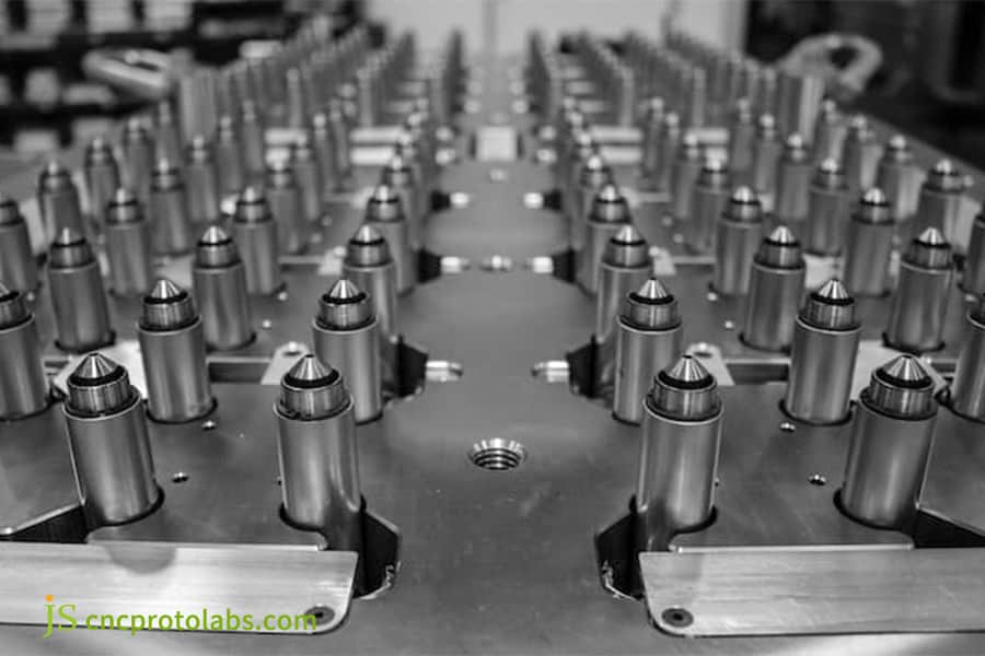
Figure 4: Operator adjusting a hot runner needle valve system in a custom injection mold.
What Draft Angle Constraints Preclude Surface Scuffing According to a Comprehensive Mold Tooling Design Guide?
Multi-cavity molds contain a large number of ejector pins. If the angles of draft and texture are different, the use of the ejector pins will result in the scratching of the product surface. In line with professional mold tooling design guide, it is considered a good practice to quantitatively relate the draft angle and the texture depth of a molded product.
Quantified Guidelines for Textured Surface Draft Angles
Based on the main mold tooling design guidelines, there is a very precise mapping between the different textured surfaces and the draft angles. For very smooth, polished surfaces, a minimum draft angle of 0.5 to 1 would be adequate. Textured surfaces classified by the VDI 3400 standard require an extra draft angle between 1 and 1.5 for each 0.025 mm increment in texture depth.
The regulation of ejection synchronization in Multi-Cavity
Plastic injection mold service of excellent quality doesn't just keep an eye on the synchronization of ejection but also measures it very strictly. Very high-standard physical factories resort to precision guide ejector plates with graphite guide bushings and also put in forced return mechanisms in large size multi-cavity mold bases to ensure the ejection of hundreds of ejector pins in 16/32 cavities is absolutely synchronous within 0.01 mm increments. This way, void deformation of the plastic part caused by non-synchronous ejection is prevented.
The conditions below are the necessary fundamental ones for demolding design when the change of single to multi cavity tooling is made:
- Draft angles for smooth surfaces should be at least 0.5°, whereas the angles for textured surfaces should be stacked in accordance to their depth.
- To have the stress in the product uniform, ejector pins should be well-spaced.
- A multi-cavity mold should be provided with a forced return mechanism that would allow the synchronous ejection.
- Points where there is a change of direction should be rounded to prevent stress concentration.
How Did JS Precision Resolve Filling Imbalances for a Civil Robotics Connector Using a Specialized Multi Cavity Mold?
Client Challenges
The project team from a civilian robot R&D company asked us for help with a core part of their product - a 30% glass fiber reinforced nylon (PA66+30% GF) precision connector with a design flow length-to-wall thickness ratio of about 145:1, which is the engineering limit for this material. The 8-cavity hot runner mold which had been supplied previously by a typical multi-cavity mold manufacturer was found during trial molding to be seriously defective: the central cavities (1-4) were completely filled, while the peripheral cavities (5-8) often experienced short shots.
Aside from that, uneven glass fiber orientation caused the dimensions and positional tolerances to go beyond 0.15 mm, which forced a complete shutdown of the mass production line.
JS Precision Solution
Thanks to being a custom injection mold builder focusing on high precision injection molding, JS Precision engineering staff re-engineered the design and effectuated a systematic optimization through four steps:
- Fluid Dynamics Reconstruction Analysis: The original design was uploaded into Moldflow for non-Newtonian fluid 3D filling simulation. It was discovered that the initial runner was omitting shear rate compensation, and so there was a pressure loss of up to 18 MPa in the edge cavities.
- Hot Runner Temperature Control Reconstruction: Refashioning the manifold and assigning independent single-point temperature control to the peripheral cavity nozzles were the two changes that were made. Increasing the peripheral nozzle temperature by 5℃ allowed melting the glass fiber over long paths to lower the viscosity of the melt.
- Core Venting Correction: By end one of high-speed CNC machining, a 0.015 mm deep and 5 mm wide vacuum venting groove was made in the end-filling area so that air resistance was eliminated.
- Pressure Holding Switching Optimization: The V-P switching point was locked at the moment of 98.2% filling using a cavity pressure sensor, coupled with an 85 MPa stepped pressure holding process.
Learning through Failure
When the tenacity was turned to run a full-on test with the first two rounds of samples, the team was aiming at upscaling the total injection pressure to fill the edge cavities, which resulted in severe flash and ejection whitening in the center cavity. Doing this proved that a filling problem of a multi-cavity fiberglass material cannot be solved simply by adjusting process parameters. It is mandatory to optimize the runner structure and temperature control compensation.
The End of the Line
Because of the final changes, the 8-cavity mold was run continuously at high speed for 72 hours. The variation coefficient on filling weight per cavity declined from 8.4% to 0.85%, and the product's dimensional and positional tolerances were kept within 0.025 mm, so fully manifesting the technical capability of a professional precision mold tooling company. Also, the cycle time has been shortened from 38 seconds to 24 seconds, and the scrap rate has fallen from 18.5% to zero.
"With the help of detailed simulation data and accurate temperature control optimization, the JS Precision team managed to rescue our mass production project which was on the verge of scrapping within 7 days, " said the client's Supply Chain R&D and Procurement Director. "Seriously, they are the kind of manufacturing gurus who also are engaged in the frontline operation."'
Complex multi-cavity filling problems require targeted structural optimization solutions. You can upload your problem mold drawings and defect descriptions to receive one-on-one engineering diagnosis and customized improvement solutions from senior engineers.
Why Choose JS Precision as Your Long Term Strategic Multi Cavity Tooling Partner for Full Scale Production?
Most importantly, precision mold tooling selection is not about who replies first but who can maintain strict quality control over the production of millions of units at high speed for a very long time without shutdowns. JS Precision offers comprehensive engineering support, from single-cavity prototyping to multi-cavity mass production of hundred thousands of units.
We operate a well-equipped, physical facility in Humen Town, Dongguan City China which is ISO 9001:2015 certified. As an established multi cavity mold manufacturer we have professional equipment like Makino high-speed CNC machines and Sodick mirror EDM machines, besides that, our core engineering team consists of 12 senior injection mold designers each of them having an average of over 15 years of experience in the industry.
Every JS Precision report is a reference to the actual parameters. Each multi-cavity mold that is ready for delivery is a finished product having passed all the quality inspection processes that the high volume mold tooling service takes. These include a complete Moldflow analysis report, an HRC 48-52 heat treatment original manufacturer traceability report, and a 24-hour full-load trial molding CMM dimensional full inspection report that together guarantee a first-pass yield of over 99.5% and assist you in keeping unit procurement costs under control.
Finding the right expert is half the battle won in mass production. Stop aimless comparisons now! Click the "Get a Customized Multi-Cavity Mold Quote Now" link below, submit your 3D CAD model and production requirements, and embark on a new journey of efficient mass production with JS Precision!
FAQs
Q1: When converting a single-cavity prototype mold into a multi-cavity mass production mold, what three main technical factors account for the biggest percentage of project failures?
Why is the omission of the non-uniform shear heat inside the runner and the nonlinear surge of clamping force.Most mold makers use no micron-level viscosity compensation resulting in flash, short shot and mold bulging issues.Fluid balance analysis should be prepared in the first step of mould design following professional standards.
Q2: How does JS Precision use technology to ensure the overall dimension of each cavity (a 16-cavity or 32-cavity high-volume multi-cavity mold) is identical in the high speed injection molding process?
JS Precision evolved three major control beams: Machinery with a positioning accuracy of 0.002 mm. Hot runner system set for balancing with a pressure variation coefficient locked below 2%. Complete dimensional inspection before delivery on all cavities by CMM.
Q3: What is the reduction rate of unit production cost for project with high volume if multi-cavity mold been used instead of single-cavity?
Although there is a higher investment cost for multi-cavity molds than for single- cavity molds, the degree of savings on unit costs is tremendous.16 (or less) cavity mold can reduce variable cost of the unit by more than 80% based on these calculation.Heating system together with hot runner system will lessen the lead time and decrease scrap rate below 2%. Investment cost will recover at the minimum number of production output at 50,000 units.
Q4:How hard vacuum quenching normally use in heat treatment of multi-cavity mould core steel? And why the hardness index is very important?
For Class 101 multi-cavities molds, life more than 1 000 000 cycles, to JS Precision also use the HRC 48-52 vacuum quenching standard and choose S136 material or H13 steel.The product will be flash out and tolerance failure when hardness is not enough.
Q5: Before the formal delivery of a multi-cavity mold, which technical document and inspection records on the quality usually need to be provided?
Professional suppliers should offer 3D drawings of the full size mold, steels certificates and heat treatment reports, Moldflow filling analysis data, T1 Trial molding process charts, and full cavities inspection report from CMM testing for multi-cavity molds.
Q6: In general, what causes the hot runner system to be more expensive when a multi-cavity mold is designed to replace a single-cavity mold? Which factors affect hot runner pricing?
Factors that affecthot runner's pricing vary from needle valve controlling is more costly than open nozzle control, more cavities, the more expensive. European&American brand is 2~3 times more expensive than Chinese & American.Specl material Wear-resistant material need to coated, cost is about 25%. You may upload the drawings to get a quotation.
Q7: How do I know that my product is right to be coined in a multi-cavity injection mold project (32 cavity or 64 cavity)?
There must be three essential conditions to produce multi-cavity molds: a steady year future total output of more than 1,000,000 units, a compact shape of a product, so that it can work with unifying qualities of conventional injection moulding machines, and a completed product design, otherwise huge later costing risks in both mold change and shut-downs.
Q8: What detail should be considered during daily continuous mass production maintenance of multi-cavity molds such that local internal stress fatigue damage not occurring?
Three significant maintenance concern for a multi-cavity mold on mass production: Every 50,000 cycles, clean venting-channel from venting deposits. Use 200C-resistance grease, Lubricate the slide and guide-powers, by cooling it below 40℃, without residuals-stresses should be put into the mouth of the material, so would not be into the thermal cracks.
Summary
The seamless transition of single-cavity prototype confirmation to multi-cavity high-performance and large-volume manufacturing is not a matter of just copying the same drawing dimension layouts, it is an arms race between the engineering revolutions of high-shear flow field geometry balancing, micron-order precision geometric tolerances copying, thermodynamically conformal cooling control, and highly rigidized mechanical fatigue resistance calculation.
Technical comparison of eight largest global suppliers of injection molds shows that, only by closely penetrating core technical aspects such as fully balanced runner parameters, vacuum high-hardness heat treatment, micron-class positioning accuracy of solid-machine, can the problems of multi-cavity size difference flash short shot be eliminated completely during continuous high-speed production, so that a single product's overall procurement cost and quality risk is brought into the range of optimum value. Stop multi-sparks negotiation and today's multi-steps construction for totally inaccurate multi-cavity shot, now directly step into strategic cooperation with our centralized solution of PID precision manufacturing center.
JS Precision has 20 senior engineering experts at your service for 2026 multi-cavity mold step-by-step DFM analysis. Would you like to increase the existing single cavity prototype to a highly productive, fully automated production line with 16, 32 or 64 cavities? Or do you have crisis issues like uneven runner balance, distortion of final product, etc. with other supplier's multi-cavities? Please send us your 3D CAD drawing and tell us what delivery you expecting. We will send you an all-in-one solution for multi-cavities mold quotation within 24 hours, including runner practicality investment, calculation of closing force and full production cost estimation, etc.

Disclaimer
The contents of this page are for informational purposes only. For JS Precision Services, there are no representations or warranties, express or implied, as to the accuracy, completeness, or validity of the information. It is the buyer's responsibility to identify specific technical requirements and request a formal parts quotation. Please contact us for more information.
JS Precision Team
ustom manufacturing solutions. With over 15 years of experience serving more than 1,000 customers, we specialize in high-precision CNC machining, sheet metal fabrication, 3D printing, injection molding, and metal stamping. Having successfully delivered over 300,000 precision parts, we maintain a 99.2% on-time delivery rate across all custom projects.
Our facility is equipped with over 100 state-of-the-art 5-axis machining centers and is ISO 9001:2015 certified. We deliver fast, efficient, and high-quality manufacturing solutions to B2B clients across 150 countries. Whether you require low-volume prototyping or large-scale customization, we support your project with lead times as short as 24 hours. Choose JS Precision for unparalleled efficiency, quality, and professionalism.
To learn more or submit your RFQ, visit our website: www.cncprotolabs.com
Resource