 English



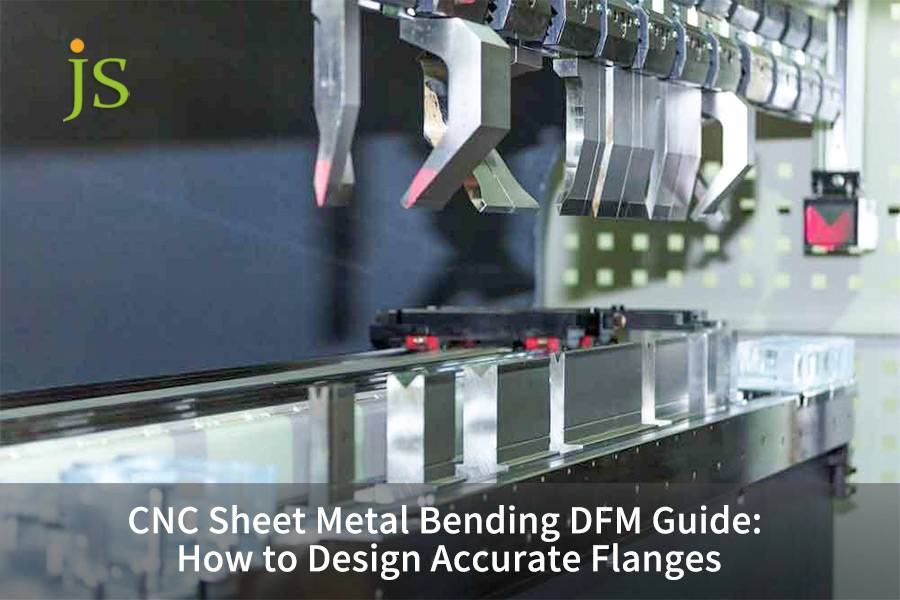

CNC sheet metal bending forms flat sheet stock into a required shape on a press brake. In flange design, three rules do most of the work: minimum flange length L_min = V/2 + 2T (never less than 4T + R), a measured K-factor of 0.35-0.45 rather than the CAD default, and a hole-to-bend distance of at least 3T + R. Get these right and you avoid material tearing, angular deviation, and fit problems in assembly.
Quick Reference: Essential DFM Rules for Accurate Sheet Metal Flange Design
|
DFM Design Parameter |
Recommended Standard Limit |
Potential Failure Mechanism |
Manufacturing Optimization Tip |
|---|---|---|---|
|
Min Flange Length |
L_min = max(V/2 + 2T, 4T + R) |
Workpiece slips into V-die groove, flange tilts |
Use narrow V-die or film-covered air bending |
|
Inside Bend Radius R |
Soft Al/St: ≥ 1T; Hi-St Al/St: ≥ 2T-3T |
Outer fiber overstretched, micro-cracks & fracture |
Avoid sharp angles, bend lines perpendicular to grain |
|
Hole-to-Bend Spacing |
Standard ≥ 3T + R; Large/Square ≥ 4T + R |
Hole stretched to oval shape in plastic zone |
Add relief slot to isolate stress if spacing insufficient |
|
Bend Relief |
Depth ≥ R + T, Width ≥ T (or ≥ 1.5 mm) |
Root tearing, side-wall bulging |
Prefer rectangular or arc relief to eliminate shear tear |
Data sources: JS Precision 2025-2026 Project Database (1,200+ European projects).
Precise sheet metal flange forming relies on the synergistic engineering control of material anisotropy compensation, V-die opening matching, and relief notch stress isolation.
How to Calculate Minimum Flange Length in CNC Sheet Metal Bending?
In CNC sheet metal bending, the shortest length of the flange is dictated by the width of the die opening (V), and you must apply L_min = V/2 + 2T (or the simplified rule L_min ≥ 4T + R, whichever is greater) to stop the workpiece edge from dropping into the V-die groove during the bend stroke. In case the flange is smaller than this geometric limitation, differential friction on the die shoulders causes sheet sliding, large angular deviation, and a safety hazard for the operator.
Air bending lower die V-groove selection standard
- For plate thickness T ≤ 3 mm, select V-groove width V = 6T to 8T.
- For plate thickness T > 3 mm, select V-groove width V = 8T to 10T.
- The V-groove width directly limits the minimum flange height through the shoulder radius clearance.
Minimum flange critical value for commonly used materials
|
Material |
Thickness (mm) |
V-Die (mm) |
Calculated L_min (mm) |
Measured L_min (mm) |
|---|---|---|---|---|
|
5052-H32 |
0.8 |
6.4 |
4.8 |
5.0 |
|
5052-H32 |
1.5 |
12.0 |
9.0 |
9.2 |
|
5052-H32 |
2.0 |
16.0 |
12.0 |
12.3 |
|
5052-H32 |
3.0 |
24.0 |
18.0 |
18.5 |
|
SPCC |
0.8 |
6.4 |
4.8 |
5.0 |
|
SPCC |
1.5 |
12.0 |
9.0 |
9.1 |
|
SPCC |
2.0 |
16.0 |
12.0 |
12.2 |
|
SPCC |
3.0 |
24.0 |
18.0 |
18.4 |
According to DIN 6935:2011 specifies that for r/s > 5 the correction factor k = 1, and uses k = 0.65 + (1/2)·lg(r/s) to calculate blank lengths for bent workpieces.
CAD Space-Constrained Ultra-Narrow Edge Solution
- Leave room for process overlap, and then remove it a second time with laser after bending.
- Use rotary bending tooling to avoid V-groove interference.
- Substitute a shallow partial-draw (coining) operation.
Want to quickly master the calculation of minimum flange height for different sheet metal thicknesses? Get quick reference tables covering 5052-H32 and SPCC.
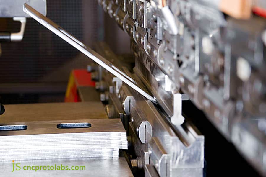
Figure 1: CNC press brake bending metal sheet flange.
How Do Bend Radii and Grain Direction Impact Precision Metal Bending Service Quality?
A reliable precision metal bending service matches the inside bend radius to the material's elongation limit (R ≥ 1T for soft metals, R ≥ 2T–3T for high-strength / heat-treated alloys such as 6061-T6) and orienting bend lines perpendicular (90°) or transverse (45°) to the material rolling grain direction. Bending parallel to the grain creates high stress concentrations along crystal boundaries, causing micro-cracking, orange peel defects, and tensile fracture along the outer bend radius.
Comparison of minimum safe bending radii
|
Material |
Parallel to Grain (Min R) |
Perpendicular to Grain (Min R) |
Failure Mode if Ignored |
|---|---|---|---|
|
6061-T6 |
3T |
2T |
Outer radius micro-cracks |
|
5052-H32 |
1.5T |
1T |
Surface orange peel |
|
SUS304 |
2T |
1.5T |
Tensile fracture |
|
SPCC |
1.5T |
1T |
Edge cracking |
According to AWS C4.6/C4.6M:2006 (Thermal Cutting — Classification and Thermal Cuts), Clause X, requires cut-edge roughness ≤ 50 µm to prevent crack initiation at the bend line.
Risks associated with setting zero radius in CAD
- Setting R = 0 directly in CAD will cause the mold indentation depth to exceed the limit.
- Zero radius causes stress concentration exceeding the material's yield strength during bending.
- Microcracks can propagate along grain boundaries, creating a risk of mass fracture.
CAM laser nesting crystal orientation standard
- During the layout stage, keep the bend line at 90° or 45° relative to the rolling direction.
- Balance material utilization with crystal orientation requirements to eliminate the risk of fracture.
- Strictly adhere to the nesting rules in the DFM bending guidelines.
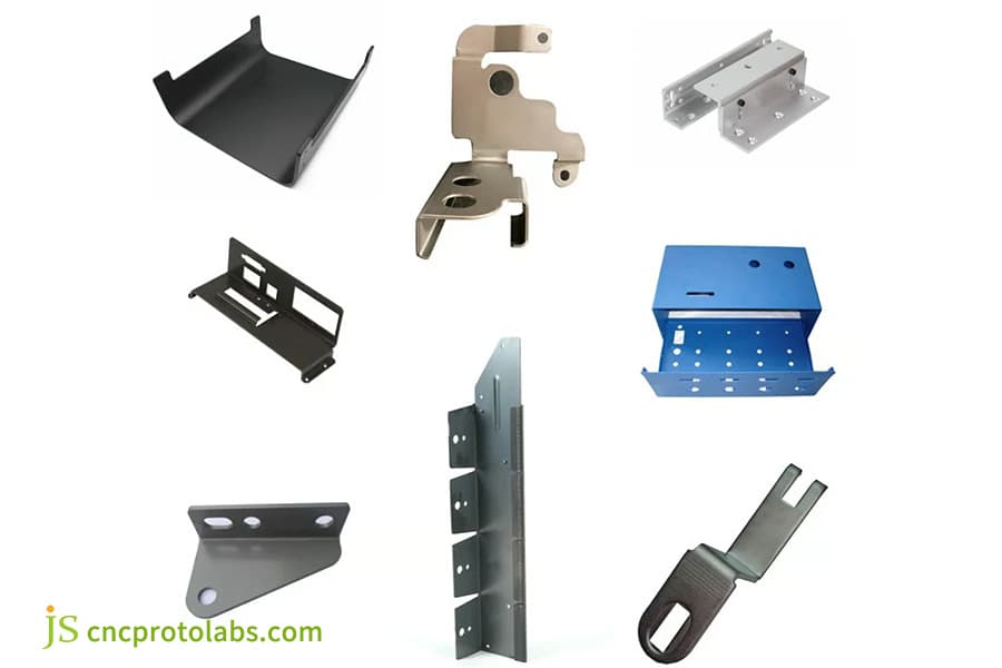
Figure 2: Various precision metal bending custom parts.
How to Prevent Hole Distortion Near Bend Lines in CNC Metal Bending?
In CNC metal bending, to minimize distortion and ensure hole-slot roundness, all cutouts are placed beyond the plastic deformation zone at a minimum distance D ≥ 3T + R from the center bend line (and it increases to ≥ 4T + R for large cutouts ≥ 25 mm). If a hole is located within the bend radius zone, the material stretching changes the circular hole into an egg- or oval shape, making it impossible to insert a threaded insert and align the fastener.
Quantification of plastic deformation zone
- The strain in the tensile zone on the outside of the neutral layer during bending can reach 15% elongation.
- The strain distribution decreases exponentially from the bend line outwards.
- Openings located within a distance of 3T + R will enter the high-strain plastic zone.
Safety margin formulas for different hole types
- For ordinary round holes, the distance between the hole and the bend line should be ≥ 3T + R.
- Large holes (≥ 25 mm) must maintain a distance of ≥ 4T + R.
- Countersunk holes and press-fit nut holes also follow the safety threshold of ≥ 3T + R.
Design compensation methods
- Laser-cut a 0.8 mm stress-relief slit between the hole and the bend line.
- Pre-compensate hole geometry with an inverse ellipse.
- Sequence the process as bend-first and three-dimensional laser cutting later.
Tired of hole deformation caused by default CAD parameters? Request sheet metal flange design optimization case studies from JS Precision and obtain a precise hole margin calculation tool for CNC metal bending to improve first-pass yield.
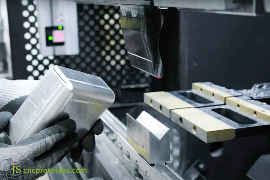
Figure 3: Worker inspecting CNC bent metal tube part.
What Are the Essential Relief Notch Rules in Sheet Metal Bending DFM?
In sheet metal bending DFM, for designing proper bend reliefs, the implementation of local relief notches with rectangular or teardrop shape is required. Notch depth should be at least R + T and notch width at least T (1.5 mm minimum). These relief cuts isolate the plastic deformation zone, preventing tearing, side-wall bulging, and misaligned seam corners during the formation of multi-axis enclosures.
Comparison of relief notch types
|
Notch Type |
Depth Rule |
Width Rule |
Application Scenario |
|---|---|---|---|
|
Rectangular |
≥ R + T |
≥ T (min 1.5mm) |
General sheet metal enclosures |
|
Arc |
≥ R + T |
≥ T (min 1.5mm) |
Aesthetic surfaces, smooth stress flow |
|
Teardrop |
≥ R + T |
≥ T (min 1.5mm) |
Complex corner junctions |
Data sources: JS Precision 2025-2026 Bending Measurement Database.
Thick Plate Design Specifications
- When the material thickness is T ≥ 3.0 mm, widen the relief notch to ≥ 2.0 mm so the laser beam and cutting tool can clear the slot.
- Multi-section bend corners require that the depth of the relief notch should be made deeper than the standard R + T.
- The quality of weld seam gap depends on the correct positioning of the relief notch.
Check out JS Precision's precision metal bending service case library now to learn how to eliminate corner tearing and ensure zero defects in mass production through standard relief notch design.

Figure 4: CNC press brake bending metal with relief notch.
How Do K-Factor and Springback Influence Precision in Custom Metal Bending Service?
Achieving precise flat pattern development in custom metal bending service relies on defining accurate K-factors (neutral axis shift ratio K = t/T) and Bend Deduction (BD = 2(R+T)tan(θ/2) - BA) rather than default CAD constants. Because high-strength alloys and stainless steel show appreciable elastic springback (1° to 5°, depending mainly on yield strength and tooling radius), both the flat-blank dimension and the CNC's dynamic angle compensation must be accurate to hold our standard-grade flange tolerance of ±0.2 mm.
Measured K-Factor Range for Commonly Used Materials
|
Material |
Yield Strength (MPa) |
K-Factor Range |
Springback Angle |
Compensation Value |
|---|---|---|---|---|
|
5052-H32 |
195 |
0.38-0.41 |
1°-2° |
+1.5° |
|
6061-T6 |
276 |
0.40-0.43 |
2°-3° |
+2.5° |
|
SUS304 |
310 |
0.42-0.45 |
3°-5° |
+2.5° |
|
SPCC |
210 |
0.35-0.40 |
1°-2° |
+1.5° |
According to DIN 6935:2011 defines the correction factor k = 0.65 + (1/2)·lg(r/s) for determining neutral axis position, where r is inside bend radius and s is sheet thickness.
Springback compensation mechanism
- Higher yield strength materials experience more elastic recovery after bending.
- JS Precision uses a closed-loop system with real-time laser angle measurement and dynamic pressure compensation to remove springback variation.
- Dynamic compensation holds batch tolerances in CNC sheet metal bending at a stable ±0.2 mm (standard grade).
According to ASTM E8/E8M-2021 specifies tensile testing of metallic materials to determine yield strength, which directly governs the 1°-5° springback magnitude in precision bending.
Facing dimensional deviations due to springback? Get a free DFM review from JS Precision. Our engineers will provide a precise K-factor correction solution for your drawings based on actual measurement data from our custom metal bending service.
How to Prevent Tooling Collisions in Multi-Flange Sheet Metal Flange Design?
Preventing tooling collisions in complex, multi-flange sheet metal flange design requires checking geometric clearances against standard punch neck profiles, goose-neck clearance pockets, and side-frame return limits during 3D CAD simulation. Deep U-channels, return flanges, and narrow internal box bends frequently collide with the upper punch body or lower bed holders if bending sequences and flange-to-web aspect ratios are designed without clearance margins.
Geometric Interference Boundary
- For deep U-channels, the punch neck clearance must exceed the flange height.
- For return flanges, use a gooseneck punch to reach the required depth.
- Tight internal box bends require segmented tooling.
Continuous bending spacing avoidance rules
- The width of the web in the Z-shaped bend should exceed half the width of the outer shoulder of the lower die.
- A safe minimum spacing between adjacent bending edges ensures no punch body collisions.
- In multi-axis forming, the flange-height-to-web ratio determines tool accessibility.
Mold Selection and Simulation
- Straight die, gooseneck die, and stepped die each have their own clearance envelope restrictions.
- 3D offline simulation software verifies the collision-free bending sequence.
- Segmented mold assembly solves complex interference scenarios.
How JS Precision Solved Flange Distortion Challenges in Medical Chassis Manufacturing?
JS Precision optimized the DFM flange parameters for a high-precision SUS304 medical analyzer chassis, successfully resolving severe hole distortion, corner tearing, and ±0.8 mm cumulative tolerance stacking across 14 consecutive bends. By redesigning relief notches, adjusting K-factors based on material batch tensile tests, and implementing specialized segmented tooling, the final assembly achieved a tight flange tolerance of ±0.15 mm and 100% first-pass yield.
Customer difficulties
There are 14 consecutive bends on the 1.5 mm stainless steel 304 frame. The bend line sat just 1.8 mm from the ventilation holes — far below the 5.5 mm safe distance (3T + R).
Holes in the first prototype elongated and twisted by more than 0.4 mm, and the corners tore. Cumulative tolerance stack-up reached ±0.8 mm, making it impossible to fit the internal optical slide rail.
JS Precision Solution
- We laser-cut a 0.8 mm stress-relief slit between the hole and the bend line, and converted the corner to a 2.0 mm-diameter arc relief.
- The CAD K-factor was re-calibrated to 0.418 from batch tensile test data. In addition, +2.5° dynamic springback compensation was applied.
- We built a segmented deep-gooseneck punch with an 8 mm narrow V-die, plus a polyurethane anti-marking film.
Lessons learned from failure
Dry-bottoming trials on the lower die revealed the root cause: a 0.15 mm deep die mark on the stainless surface, plus micro-cracks on the outer bend edge.
The team immediately abandoned the dry-bottoming approach and switched to film-covered air bending technique, enlarging the relief groove to 2.0 mm to eradicate surface and crack defects.
Final result
- All 14 flange openings held ±0.15 mm, well inside the ±0.3 mm drawing requirement. For 14 consecutive bends in 1.5 mm SUS304 that sits between our standard grade (±0.2 mm) and precision grade (±0.1 mm).
- Hole roundness deformation is controlled within 0.05 mm to meet high-precision assembly requirements.
- 1,500 sets shipped with zero defects, saving customers 40% in assembly time.
Data source: JS Precision Internal Engineering Report Case Study #MED-2025-08: SUS304 Chassis Precision Forming Analysis.
Facing challenges like flange distortion in medical chassis? Send your STEP drawings to JS Precision now to receive a free DFM review report from senior engineers, with manufacturability optimization solutions provided within 24 hours.
FAQs
Q1: Why do sheet metal flanges tear at the corners during CNC bending?
Flange corners tear because there is no bend relief at the corner joint, so tensile and shear stress tear the material directly. Add a rectangular or rounded relief notch in CAD — depth ≥ R + T, width ≥ T (1.5 mm minimum) — and you block stress transmission, preventing corner splits.
Q2: What is the minimum safe distance between a hole and a bend line?
Keep ≥ 3T + R between the hole edge and the bend tangent line; for holes ≥ 25 mm or irregular shapes, increase to ≥ 4T + R. If a hole falls inside the plastic stretching zone, the round hole elongates into an oval, which prevents screw assembly and can loosen press-fit nuts.
Q3: Why should engineers avoid using CAD default K-factors for flat patterns?
The CAD default K-factor of 0.44 is only an empirical approximation for mild steel. Sheet hardness, die V-opening, and the air-bending radius-to-thickness ratio determine the real K-factor. If you apply that default to aluminium or stainless steel, your flat-pattern dimensions will be off by 0.5 mm to 1.0 mm.
Q4: What is the main difference between air bending and bottoming?
Air bending controls the angle by pressing the punch into the V-groove depth, without the sheet metal contacting the die bottom. It has a small tonnage and high versatility. Bottoming completely presses the sheet metal to the bottom of the die for forming, achieving high precision but requiring 3 to 5 times more tonnage and resulting in severe die wear. Modern high-precision sheet metal work often employs air bending with closed-loop compensation.
Q5: How can tooling collisions be prevented in multi-flange enclosures?
When designing multi-segment bends or deep U-shaped structures, the flange height must not exceed the effective throat depth of the upper die, and sufficient clearance must be reserved between bends. Before blanking and processing, interference simulation of the entire bending process must be performed using 3D software. If necessary, gooseneck dies or segmented combination dies should be used to provide clearance.
Q6: How do bending rules differ between 6061-T6 and 5052-H32 aluminum?
5052-H32 and 6061-T6 differ on two counts: minimum inside radius and grain sensitivity. 5052-H32 is highly formable — R ≥ 1T with the bend line perpendicular to the grain, rising to R ≥ 1.5T parallel to it. 6061-T6 is far less ductile — R ≥ 2T perpendicular to the grain and R ≥ 3T parallel to it. Where the nesting allows it, always run the bend line perpendicular (90°) to the rolling grain direction; if a parallel bend is unavoidable, use the larger radius from the table above. Bending parallel to the grain concentrates stress along grain boundaries, which produces micro-cracking, orange peel, or outright fracture on the outer radius.
Q7: What manufacturing tolerances can JS Precision achieve in Precision Metal Bending Service?
JS Precision is equipped with a high-precision CNC electric servo bending machine and an online laser angle measurement system. For carbon steel, stainless steel and aluminum alloy flanges, the linear dimensional tolerance can be stably controlled within ±0.2 mm (precision grade up to ±0.1 mm), and the angular tolerance can be controlled within ±0.5°.
Q8: What key factors determine the quotation for a Custom Metal Bending Service?
The metal bending quotation mainly depends on the material and thickness of the sheet metal, the number of bending steps, the frequency of die changes and adjustments, the tolerance level, and the surface anti-marking requirements. Standardizing the bending radius of all parts during the design phase and reserving clearance for standard dies can reduce machine setup and processing costs by 20% to 35%.
Summary
The core of designing high-precision sheet metal bending flanges lies in adhering to material mechanics and die forming limits. Apply four rules at the CAD stage — (1) L_min ≥ 4T + R, (2) hole-to-bend ≥ 3T + R, (3) standard stress-relief notches, (4) flat-pattern correction using a measured K-factor — and you eliminate over 90% of cracking, hole distortion, and assembly-interference risk before the part ever reaches the brake.
JS Precision, with its extensive experience in precision bending and closed-loop compensation system, provides reliable manufacturing assurance for industries such as medical and electronics. Upload your STEP or DXF drawings to our official engineering evaluation window immediately, and our senior DFM engineers will provide you with free manufacturability analysis and highly competitive quotations within 2 hours!

Disclaimer
The contents of this page are for informational purposes only. For JS Precision Services, there are no representations or warranties, express or implied, as to the accuracy, completeness, or validity of the information. It is the buyer's responsibility to identify specific technical requirements and request a formal parts quotation. Please contact us for more information.
Resource

