 English



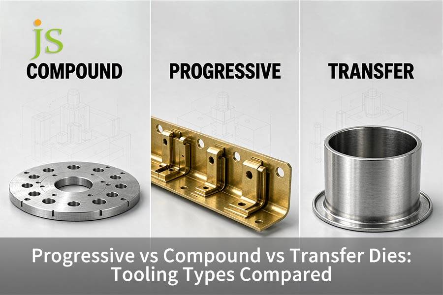

Choosing between Progressive vs Compound vs Transfer Dies depends on three engineering hard constraints: Part geometry depth, tolerance concentricity, and annual volume.
For flat and highly accurate 2D pieces needing concentricity between edge and hole within ±0.01 mm in one die stroke, compound dies work best, while progressive dies are suitable for high volume production (above 50,000 pieces per year) of 3D complicated and mini-to-medium parts using a carrier strip. For deep drawn or larger pieces (above 250 mm), transfer dies are essential.
Each stamping die type manages raw material conveyance differently: compound dies use stationary nested tooling, progressive dies have the part moved through the stations on strip stock by precision strip carriers, and transfer dies have automatic mechanical gripper fingers that move singles from station to station.
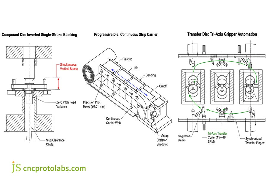
Figure 1: Kinematic comparison showing single-axis inverted compound blanking, continuous progressive carrier strip advancement, and tri-axis automated transfer gripper rail cycles.
Stamping Tooling Architecture Quick-Selection Benchmark
Choice of tooling architecture represents an element of the original fundamental engineering trade-off: freedom of the workpiece for aggressive 3D forming and deep drawing versus the constraint of the rigid carrier strip for micrometer part accuracy and cycle speeds up to 600 SPM.
| Tooling Architecture | Primary Part Geometry & Tolerance Envelope | Economic Stroke Speed (SPM) | Typical Material Yield | Tooling Capital (NRE) | Break-Even Point (BEP) |
| Compound Die | Flat 2D profiles, concentricity ±0.01 mm, thickness 0.1–4.0 mm |
40–120 SPM | 65%–85% | $3,000–$10,000 | 15,000–50,000 pcs |
| Progressive Die | Multi-bend 3D forms, pitch tolerance ±0.025 mm, width ≤350 mm |
100–600+ SPM | 50%–70% (carrier web scrap) | $15,000–$80,000+ | >100,000 pcs |
| Transfer Die | Deep-drawn shells (>30 mm), large stampings, tolerance ±0.05 mm |
15–40 SPM | 80%–92% (singulated blanks) | $40,000–$150,000+ | 50,000–150,000 pcs |
Data Sources: Industry Tooling Aggregates and Precision Metalforming Association (PMA 2025 Benchmarks).
Compound Die vs Progressive Die: Which Delivers Better Flatness and Concentricity?
Many cutting operations blanking, piercing in one press stroke are carried out by a compound die. No movement of stock allows parallel and perfect registration between internal holes and external edge, a concentricity and ultimate size down to ±0.01 mm. The progressive die introduces feed pitch errors over several stations. Compound tooling is the usual engineering answer to ultra-flat washers shims laminations.
Inverted Tooling Architecture and Concentricity Control
In Compound Die Stamping, all of the cutting takes place concurrently in one vertical plane, which toolmakers create using inverted tool fabrication:
- Upper Die Set: Holds outer blanking die cavity and corresponding inner piercing punches on the upper ram plate.
- Lower Die Set: Contains the master blanking punch with internal clearance holes for slug removal.
- Strip Clamping: Spring biased stripper pads clamp the strip tightly against the lower die face before punch entry.
Since the hole piercing and perimeter blanking occur in an identical small fraction of a second, the raw stock maintains attachment to the die, covering no additional distance.There is zero feed vibration, no strip travel, and no pitch variance. Dimensional concentricity depends entirely on wire EDM cutting precision of the die components, holding limits down to ±0.01 mm.
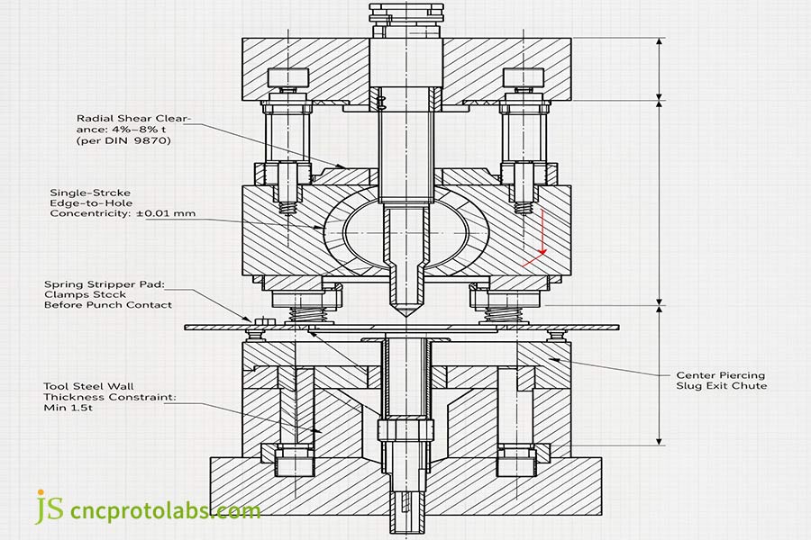
Figure 2: Inverted compound die cross-section illustrating simultaneous vertical shearing, holding hole-to-edge concentricity to ±0.01 mm with 4%–8% t cutting clearance per DIN 9870.
Under DIN 9870 stamping tool standards, which are the basic engineering tolerances of the punch-to-die shear clearances, controlling the radial pitch within 4%–8% of the material thickness (t) per side inhibits punch-die wall microcrack and ensures blanking tonnage.
Cumulative Feed Error and Progressive Strip Dynamics
A progressive die performs cutting, bending, and punching across multiple stations on the press bed. The coil stock moves through a specific feed pitch between each stroke. Today servo feeders automate this index operation with high accuracy, but there are small physical deviations between sections of the strip:
- Feeder Slip and Camber: Coil curvature and feed roll micro-slip introduce a positional variance of ±0.015 mm to ±0.025 mm over 5 to 15 stations.
- Pilot Hole Distortion: Misalignment occurs when bullet pilots collide with pierced holes. Strip inertia at higher velocities forces pilots into hole edges, with resulting minor hole ovality.
- Internal Stress Imbalance: Unbalanced shearing will release residual rolling stresses, which can twist the sheet or cause oil-canning before the part is cut off.
Progressive stamping needs special restrike or flattening stations to maintain flatness within 0.02 mm. The compound die sets flatness within 0.015mm in one press-off without secondary flattening. This pitch-to-pitch registration variation shows the basic distinction between progressive die stamping and single-stage stamping, where individual, separate steps protect blanks from intermittent strip feed errors.
Physical Limits and Structural Failure Modes
The only major design restriction for compound dies is that of tool steel wall thickness. Since blanking and piercing are performed in the same opening, the ring of the tool steel between the outer cut and hole is under great cyclic shock:
- Minimum Wall Rule: The tool steel wall has to be 1.5 times that of the material thickness between the punch and die openings to avoid fatigue cracking.
- Tonnage and Wear Limits: For any stock thicker than 4.0 mm or alloy over 450 MPa tensile strength, the wall may be too thin and can be worn away by fatigue.
- The Progressive Alternative: Progressive dies get around this problem by having a dedicated blanking station and a dedicated piercing station, using heavy duty backup blocks.
Tooling Tolerance and Physical Speed Limits
Compound dies give a concentricity and flatness on flat parts, while progressive dies achieve high-speed multi-bend forming with limited pitch accuracy.
| Tooling Architecture | Flatness (mm) | Concentricity (mm) | Max Sheet Gauge (mm) | Typical Speed (SPM) | Pitch Error (mm) |
| Compound Die | <0.02 | ±0.010 | ≤4.0 | 40–120 | Zero (Single stroke) |
| Progressive Die | 0.05–0.10 | ±0.025 | ≤3.0 | 100–600+ | ±0.015 to ±0.025 |
| Transfer Die | 0.05–0.15 | ±0.050 | ≤6.0 | 15–40 | ±0.030 to ±0.050 |
Data Sources: DIN 9870 Stamping Tool Standards and JS Precision Metrology Verification (2026).
Progressive Die vs Transfer Die: How Do Pitch Tolerances Compare at High Volumes?
Progressive die stamping pushes a continuous strip of metal coil through a series of workstations while attached to a designed carrier web. This setup enables ultra-high production speeds from 100 to over 600 strokes per minute for small-to-medium parts. Transfer die tooling advances a blank (on a carousel) with mechanical grippers at a much slower cycle rate. Progressive dies rely on precision pilot pins entering pre-pierced strip holes to correct pitch variance down to ±0.015 mm before punch entry.
Carrier Strip Design and Web Camber Control
The continuous carrier strip is the foundation of Progressive Die Stamping. It ensures the component remains attached to the coil so the press can continuously feed with high velocity. Tool designers select from three standard carrier configurations:
- Single-Edge Carrier: The least material used, but susceptible to camber and twist on broad or deep sections.
- Two-Edge Carrier: Clamps either edge of the strip for complex forming.
- Center Spine Carrier: Connects parts with center ribbon containing expansion loops that enable the metal to draw inward without extending pilots off centerline.
Under DIN 1544 precision strip tolerances, coil thickness consistency ensures pilot pins maintain registration without wall scouring. When forming pulls the stock inward without proper relief cutouts, the unevenly extended carrier ribbon can cause a coefficient of expansion. Strip camber greater than 0.5 mm per 1,000 mm of strip length causes the stock to bind up against die guides resulting in misfeeds and punch breakage.
Pilot Pin Registration at High Cycle Rates
To keep high-volume small parts in a progressive die vs transfer die accurate at 200-600 SPM with:
- Pilot Clearances: Guides bullet pilots are installed in guide holes to provide 0. 008 mm to 0.012 mm of radial clearance.
- Feeder Roll Release: Feeder rolls should release strip clamping 10° to 15°before pilots bottoming out and allow the bullet pins to pull the strip into precise registration.
- Dynamic Inertia Risks: Above 400 SPM on heavy gauge strip, coil inertia tears pilot hole edges, causing pitch variance to drift to ±0.030 mm to ±0.050 mm.
Idle Station Placement and Cam Clearance
High-speed progressive dies integrate deliberate empty spaces called idle stations:
- Structural Die Volume: Empty stations leave adequate tool steel between working pockets, preventing die block fractures under heavy load.
- Cam Slide Clearances: Idle stations provide open space to accommodate mechanical cam slides or wedge units for horizontal piercing of side holes.
- Sensor Packaging: Vacated slots house the proximity probes, fiber-optic eyes, and mechanical pins that sense misfeeds or pulled slugs before punch engagement.
Transfer dies do not require idle stations because each forming station uses an isolated die shoe. When transverse features exceed cam slide travel limits, comparing metal stamping vs. CNC machining determines whether stamping tooling remains viable against multi-axis milling.
Why Is Transfer Die Stamping Essential for Deep-Drawn and Heavy Parts?
Transfer die stamping entirely isolates the blanking operation from the feed coil by employing mechanical fingers, vacuum grippers, or walking beams at the first blanking station, to move individual blanks. This architecture removes the stiff carrier web constraints, allowing very deep drawing, multi-axis part rotation, and aggressive restriking. This is the requisite production tooling for deep shells (>30 mm draw depth) and heavy automotive structural stampings requiring high material yield.
Kinematic Motion Profiles of Mechanical Transfer Grippers
Instead of pulling parts with scrap coil, Transfer Die Stamping uses automated gripper rails timed to the press ram:
- Clamp Stroke (X-axis): Mechanically advances fingers 50 mm to 150 mm to inwardly grip the edges of component.
- Lift Stroke (Z-axis): 20 mm to 100 mm lifting of the blank clear of the bottom draw cavities.
- Pitch Stroke (Y-axis): Indexes the part forward to the subsequent station across distances from 200 mm to over 800 mm.
- Release Stroke: Fingers unclamp, place the part into the die nest, and return to home position.
Because transfer bars accelerate and decelerate heavy individual stampings, mechanical inertia caps press speed at 15 to 40 SPM. But isolating the blank from the coil permits operations that are impossible for a progressive die: 90° or 180° part turnover, reverse cup drawing, and continuous peripheral trimming.
Raw Material Scrap Efficiency and Nesting Geometry
Material yield differences often determine tooling selection on large parts:
- Progressive Die Scrap: Strip stock needs carrier rails, pilot hole margins, and other inter-station skeleton webs. 50%-70% yield on round or irregular shaped parts.
- Transfer Die Efficiency: Parts are blanked from tight nest coil layouts (zig-zag blanking), or are cut from pre-sheared blanks. Material yield increases to 80%–92%.
For structural programs handling several hundred metric tonnes of alloy steel per year, a 15% to 20% reduction in coil scrap amounts to a strong economic case for the original capital expenditures required for transfer dies and automation rails.
The Limiting Draw Ratio and Carrier Web Failure
Deep drawing pulls sheet metal into a die cavity over a polished draw radius:
- Inward Metal Flow: As the punch pulls material into the cavity, the diameter of the outside blank decreases.
- Carrier Web Tearing: In a progressive die, this contraction pulls violently against the carrier web. When draw depths are above 30 mm, the carrier tabs are pulled out thin, twisted, and torn.
- The Transfer Solution: Transfer dies avoid this failure by blanking the workpiece completely free at station one. Dedicated nitrogen gas cushion cylinders exert equal pressure all the way around the edge, enabling flow into deep cavities without tearing.
When comparing seamless enclosures to fabricated assemblies, explore our structural guide on deep draw stamping vs. welded fabrication.
Progressive vs Compound vs Transfer Dies: Which Tooling Best Fits Your Project?
Stamping die selection balances part dimensions, dimensional tolerance, metal scrap percentage, and total production volume against tooling capital costs. For tight flat form parts, a compound die reduces the NRE ($3,000–$10,000). For complex 3D stampings produced over 100,000/ year, progressive dies offer the best unit cost, yet represent the highest tooling capital costs ($15,000–$80,000+). Transfer dies are ideal for deep draw or massive parts where raw material scrap savings compensate a lower stroke pace.
Cross-Process Tooling Evaluation
Switch to progressive dies if you will be running small, multi-bend, 3D parts at high production rates. For parts with a depth of over 30 mm, large parts, or when maximizing raw material scrap savings are the highest priorities, switch to transfer dies. For flat 2D parts where flatness and concentricity are critical, and the initial tooling costs are less critical, go with a compound die.
| Tooling Type | Max Draw Depth | Material Yield | Tooling NRE | Primary Failure Mode |
| Compound Die | <5.0 mm | 65%–85% | $3,000–$10,000 | Tool wall chipping on stock >4.0 mm |
| Progressive Die | <30 mm | 50%–70% | $15,000–$80,000+ | Carrier web tearing, pitch drift |
| Transfer Die | >30 mm (to 300 mm) | 80%–92% | $40,000–$150,000+ | Part slip during fast deceleration |
| CNC Soft Tooling (Counter-Process) | Limited by press brake | 70%–85% | $0–$2,500 | HAZ micro-cracks, unviable unit cost |
Data Sources: Precision Metalforming Association (PMA 2025 Report) and ISO 9013 Thermal Cutting Reference Data.
Tooling Selection Roadmap: From Part Geometry to Production Run
The selection process of tooling using the component specification details includes the following three steps:
Step 1: Check Part Planarity
- Is the component strictly flat with zero vertical forming?
- If yes and volume is between 15,000 and 50,000: Select a Compound Die to keep NRE and hole concentricity to a minimum.
- If yes and volume exceeds 50,000 units: Then select a High-Speed Progressive Blanking Die.
Step 2: Evaluate Draw Depth & Orientation
- Is the geometry then necessitating to draw depth of more than 30 mm, or does the part need to flip over between operations?
- If yes: Select a Transfer Die to remove carrier web stretching and tearing.
Step 3: Calculate Volume Amortization
- What is the targeted annual production run?
- Less than 5,000 parts: Use Laser Cutting and CNC Press Brake Soft Tooling to eliminate important tooling capital risk beforehand.
- 5,000 to 50,000 parts: Select Modular Single-Station Line Tooling.
- More than 50,000 parts (strip width up to 350 mm): Select a Multi-Station Progressive Die for the least per-piece cost.
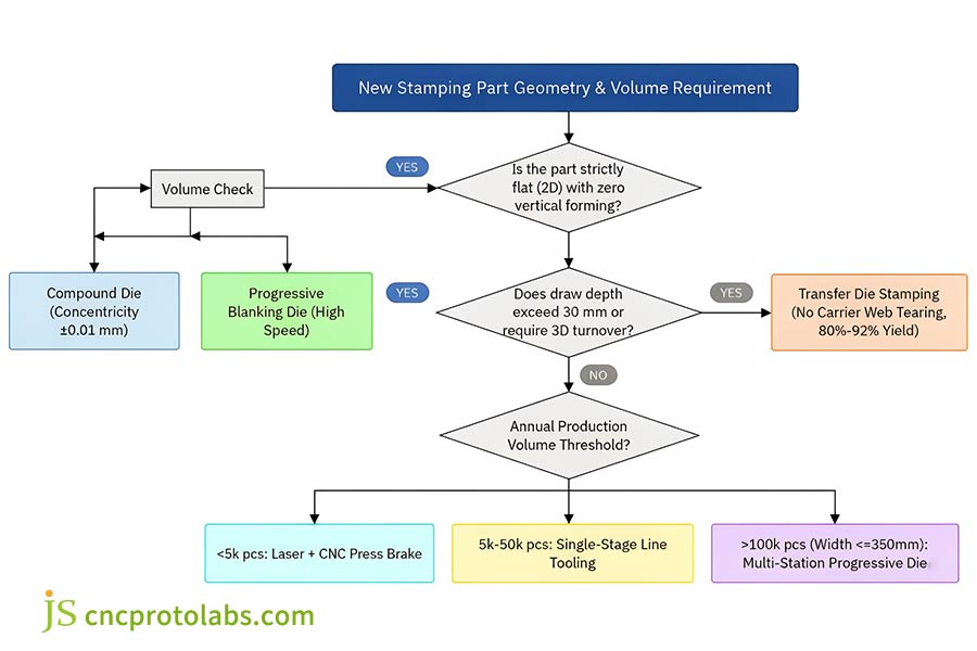
Figure 3: Step-by-step engineering decision roadmap screening stamping dies by geometry planarity, 30 mm draw depth limits, and annual volume amortization thresholds.
Tooling Capital Amortization Dynamics
Tooling decisions must account for initial NRE against continuous manufacturing run costs:
- Under than 5,000 Parts: Avoid hard tooling. Pricing can carry the laser-cutting and brake-forming cost, so there is no unrecoverable tooling capital at risk.
- 15,000 to 50,000 Parts (Flat Blanks): Compound die amortizes on the initial run. Maintains tight tolerances without large NRE of a progressive tool.
- Over 50,000 Parts (Complex Forms): Progressive dies provide the lowest total cost. Operating at 300 to 600 SPM drives machine and labor costs down to cents per piece.
According to empirical field research from the Precision Metalforming Association (PMA 2025 Benchmark Report) in which tooling wear rates for high speed stamping steels were studied, under normal conditions, standard AISI D2 inserts are capable of 500,000+ strokes before requiring regrinding, provided that pilot alignment is maintained and punch clearances are correct.
On heavy structural stampings, reducing coil scrap by 15% to 20% through transfer nesting offsets tooling capital. These material utilization metrics align with the coil feed and tonnage specifications defined in our sheet metal stamping guide.
Stamping Die Selection for Critical Alloys: Which Tooling Works for EMI Shields and AHSS?
Alloy selection and sheet thickness impose strict mechanical limits on tooling types. For 0.1–0.3mm stainless steel EMI shielding plates, compound dies are required to prevent micro-burrs and strip deformation, whereas high-speed progressive dies need floating stripper plates against thin-gauge web jam. For automotive AHSS structural parts (>600 MPa), transfer dies remove violent springback and strip rupture via destruction of fragile continuous ribbons, with the subsequent release of isolated high-tonnage nitrogen gas spring stations.
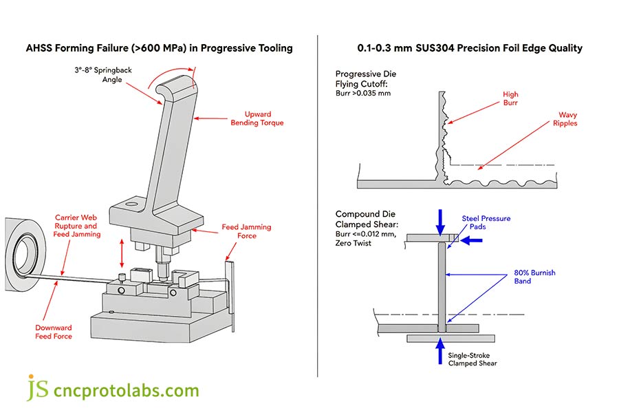
Figure 4: Material failure modes under extreme stresses: AHSS springback tearing progressive carrier webs versus full-face compound clamping controlling thin foil burrs under 0.012 mm.
Challenge 1: Thin-Gauge EMI Shielding (0.1–0.3 mm SUS301/304)
The precision shielding enclosures for electronic equipment necessitate thin metal, tightly spaced perforation patterns, burr height (≤0.015 mm) and a very low flatness tolerance (≤0.03 mm):
- The Progressive Die Problem:
Ultra-thin stainless steel strip buckles/flares when forced through a high speed die at 300+ SPM. Carrier tabs are twisting under press vibration causing the hole positions to drift. A final parting punch is damaging thin tabs by pushing against them producing burrs that are greater than 0.030 mm increasing the likelihood of short circuits to occur on circuit boards.
- The Compound Die Solution:
A compound die keeps the thin sheet under compressed between hardened steel pressure pads and cuts, shearing both internal grounding holes and outer perimeter simultaneously to under burrs of 0.012 mm with zero strip twist.
When evaluating compound die vs progressive die for EMI shielding plates, JS Precision’s engineering team utilizes custom metal stamping services to validate strip layouts and verify punch clearances before cutting tool steel.
Challenge 2: Advanced High-Strength Automotive Steel (AHSS >600 MPa)
Automotive structural parts like brackets, seat frame rails or cross members are gradually calling for use of Dual Phase steels like DP600, DP800 and DP980, which are checked by ASTM A1008 / A1079 automotive testing standards. Although these grades offer an excellent strength-to-weight ratio, they introduce serious stamping challenges:
- Severe Springback: High yield strength causes formed flanges to spring open by 3° to 8° upon die release.
- Progressive Strip Failure: When stripback occurs in a progressive die, formed tabs are driven hard against the permanent carrier strip. This distorts the carrier, snags it on the lifters, and eventually tears it in two, aborting the press line.
- Transfer Die Solution: The transfer die completely cuts the blank free in station one thereby eliminating strip failure. Mechanical isolation of each station allows toolmakers to fit the tool with large nitrogen gas cylinders (50 kN to 200 kN) and dedicated restrike stations that over-bend tabs by 4° to 6° to lock in finished dimensions.
When choosing between a transfer die vs progressive die for high-strength steel automotive structural parts, transfer die offers the tonnage and mechanical isolation of the high strength steel to control the extreme spring back without breaking the carrier strips.
FAQ
Which die is best for high volume production runs?
When evaluating which die for high volume manufacturing, Progressive Die Stamping suits volumes over 50,000 units with speeds of 100–600+ SPM. For deep-drawn parts, Transfer Die Stamping achieves 80%–92% material yield, reducing stock costs despite lower speeds (15–40 SPM).
What is the main cost difference between compound and progressive tooling?
Comparing Compound Die vs Progressive Die, Compound Die Stamping requires significantly less upfront tooling capital ($3,000 to $10,000) because all cutting occurs in one station. Progressive dies require $15,000 to over $80,000 due to multiple complex stations. Progressive tooling is only economical with really high volumes when that tooling can be amortized through hundreds of thousands of parts.
Progressive die vs transfer die for high volume small parts: Which is better?
Comparing Progressive Die vs Transfer Die, for the specific scenario of Progressive die vs transfer die for high volume small parts under 100 mm, progressive tooling is almost always superior. The continuous carrier web moves small parts securely at 200 to 600 SPM. Transfer grippers cannot move small parts that fast without dropping them, making transfer dies practical only when parts need complex deep drawing or rotation.
How does material scrap rate compare across the three stamping die types?
In Stamping Die Selection, material yield varies by stamping die types:
- Transfer dies: 80%–92% yield using pre-sheared blanks.
- Compound dies: 65%–85% yield based on part spacing.
- Progressive dies: 50%–70% yield due to continuous carrier and skeleton scrap.
How do tolerances and part flatness vary between compound and progressive stamping?
Compound Die Stamping holds flatness <0.02 mm and concentricity to ±0.01 mm in a single stroke. Progressive Die Stamping introduces ±0.015 mm to ±0.025 mm pitch variation and slight twist across multiple feed and bending stations.
Can a progressive die handle deep-drawn parts?
In progressive vs compound vs transfer setups, progressive dies only allow shallow draws (<30 mm). Depths exceeding 30 mm stretch and tear the carrier ribbon, requiring transfer dies instead of planar Transfer Die vs Compound Die tooling.
What are the primary failure modes when stamping AHSS structural parts in progressive dies?
For transfer die vs progressive die for high-strength steel automotive structural parts, progressive dies fail through carrier web tearing, pilot hole rupture, and strip binding on steels >600 MPa. Transfer dies eliminate strip breakage using independent nitrogen gas restrike stations.
How should tooling architecture be selected for thin metal shielding components?
In compound die vs progressive die for EMI shielding plates, 0.1–0.3 mm stainless steel strips ripple in progressive feeds, causing burrs >0.030 mm. Compound tooling clamps stock flat to shear holes and edges simultaneously, keeping burrs ≤0.012 mm without twist.
Summary
Choosing between Progressive vs Compound vs Transfer Dies takes care of the balance between the upfront tooling capital, part forming depth and material scrap:
- Compound Die Stamping: Flat 2D blanks requiring tight concentricity (±0.01 mm) and flatness in a single stroke.
- Progressive Die Stamping: High-volume (>50,000 units), multi-bend 3D components running continuously on a carrier strip.
- Transfer Die Stamping: Deep-drawn shells (>30 mm) and large footprints where carrier ribbons tear under forming stresses.
Finalizing your Stamping Die Selection during early design-for-manufacturing (DFM) reviews locks in unit costs and eliminates post-assembly die modifications. To validate strip layouts, calculate press tonnage, or evaluate material utilization before cutting tool steel, submit your CAD models to request a custom stamping tooling quote at JS Precision.

Resource

