 English



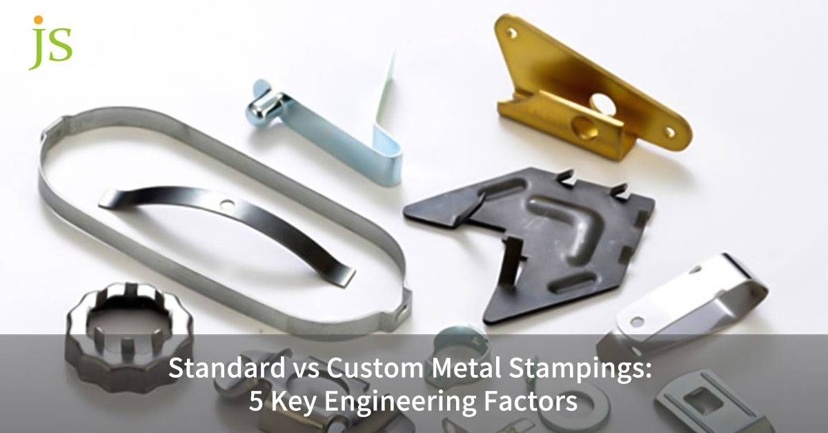

The main differences between standard vs. custom metal stamping centers largely depend on tooling amortization, geometric flexibility, and the level of tolerance accuracy that can be achieved.
Standard stamped parts utilize pre-existing standardized dies to eliminate upfront non-recurring engineering (NRE, the one-time design engineering cost for CAD tooling, CAM programming, and wire electrical discharge machining) charge but component shapes are limited to fairly simple brackets, flat washers or generalized clips, utilising general stamping tolerances of approximately 0. 2mm to 0. 5mm.
However, custom tooling, while requiring an initial diecost of between $3,000 to greater than $50,000 can allow for complex shapes, very tight engineering tolerances down to ±0. 01mm, multi-stage progressive die features and specialized springback compensation procedures for difficult alloys.
Executive Engineering Summary
Select standard stamped parts when annual shipment volumes are under 5K and the envelope of the part can be formed using stock die shapes; purchase dedicated custom stamping tooling when geometric tolerances are tighter than ±0.1 mm, annual volumes can exceed 20K, or complex three-dimensional geometry takes multi-station progressive processing.
| Engineering Evaluation Factor | Standard Stamping (Standardized Dies) | Custom Tooling Stamping (Dedicated Dies) |
| Upfront Tooling Investment | $0 for universal die tooling already present | $3,000 to >$50,000 (Dedicated single-stage or progressive tooling) |
| Tolerance Class & Precision | Rough to Medium (DIN 6930-2 Class M or C, ±0.2 mm to ±0.5 mm) | Precision with higher tolerance (DIN 6930-2 Class f, approximately ±0.01 mm to ±0.05 mm) |
| Economic Break-Even Volume | Structurally optimal for <5,000 pieces/year or functional prototypes | High cycle efficiency for over 20,000 pieces/year serial production. |
| Geometric & Feature Freedom | Constrained to existing tooling profiles (washers, clips, 90° bends) | Open 3D forming, colletive deep draw, coinage, and embossing. |
| Material Selection Flexibility | Limited to standard stock coils (SPCC steel, 6061-O aluminum, H62 brass) | Full access to specialty stainless alloys, titanium, and beryllium copper |
How Does Tooling Cost Dictate Standard Stamping vs. Custom Tooling Selection?
Standard stamping vs custom tooling selection depends on the total production volume amortizing the die expenditure. Standard stamping does not involve any tooling expense and that is why it is more economic unit cost up to 5,000 units, while custom metal stamping cost is considerably lower per cycle than the standard one, about 40%-70% lower cost after production of more than 5,000 units because high speed progressive die excludes secondary machining operation and utilizes almost 100% of scrap strip.
Comparison Matrix for Metal Forming Technologies
Proper selection of metal forming technology means comparing the costs of initial tooling with the required precision and potential weaknesses. Conventional die stamping is available right away and does not involve any tooling costs, although it cannot meet strict tolerances below ±0.2 mm at the joint points. Progressive dies need about 4-10 weeks for tooling but enable manufacturing of parts for less than $0.15 per unit.
| Forming Process | Tooling NRE | Linear Tolerances | Geometric & Structural Capability | Critical Failure Mode & Process Redline |
| Standardized Die Stamping | $0 (Shared tooling) | ±0.2 to ±0.5 mm (DIN 6930-2 m/c) | Flat 2D profiles, 90° bends, basic slots | Assembly Binding: Loose stack-up tolerances cause fit failure |
| Laser + CNC Brake | $0 – $300 (Basic CNC setup charges) | ±0.1 mm to ±0.25 mm (ISO 2768-m) | 2D profiles + multi-axis flanging | Cycle Bottleneck: >60s/pc cycle time unviable above 2k pcs |
| Custom Soft Tooling | $1.5k - $5k (P20/Urethane) | ±0.05 mm to ±0.1 mm (DIN 6930-2 Class m) | Dedicated embossments & single-stage draws | Tool Wear Drift: Soft die edges round rapidly after 5,000 strokes, causing burrs >10% sheet thickness. |
| Progressive Hard Die | $8k - $50k (Carbide/D2) | ±0.01 mm to ±0.05 mm (DIN 6930-2 Class f) | Multi-stage coining, deep draw, in-die tapping | High Modification Cost: Post-hardening revisions mandate wire-EDM rebuilds |
Engineering Rule:
IF Annual Volume > 10,000 units AND Positional Tolerance < ±0.05 mm,
THEN Adopt Custom Progressive Hard Tooling (Cycle cost control & no drift).
Tooling Amortization and Discrete NRE Cost Drivers
The financial decision making regarding standard die parts versus custom metal stamping tooling starts with the cost analysis of the non-recurring engineering (NRE). The standardized parts do not require specific capital investments since the press facility has already amortized the universal tooling with multiple program production cycles.
Rather than just an all-around setup cost, the NRE required in advance for dedicated tooling becomes a more specific series of five manufacturing line costs:
- Tool Design and CAM Simulation: 3D strip layout modeling, Finite Element Analysis (FEA) for stress concentration, and press tonnage sizing.
- Subtractive Machining: high speed CNC die shoes roughing, guide pillar fine boring, cavity pocket milling.
- Vacuum Heat Treatment: heat treatment of the punch steel material (like D2, DC53, or powder metallurgy steels) to a hardness of 60-62 HRC.
- Micro-WEDM Finishing: multi-pass wire electrical discharge machining of punch cutting edges with tolerance of ≤0.002 mm.
- Die Assembly and T0/T1 Tryout: manual bench fitment and spring balance, initial strip testing under high press tonnages.
The cost engineering experts determine the cost threshold based on the standard equation:
Total Cost Per Unit = Initial Tooling Investment per Total Production Volume + Raw Material Cost Per Unit + Press Stamping Stroke Cost.
Volume Amortization Breakdown:
| Production Volume (Units) | Standard Stamping (Unit Part Cost) | Custom Soft Tooling ($3,000 NRE + Unit Cost) | Custom Progressive Tooling ($12,000 NRE + Unit Cost) | Optimal Engineering Choice |
| 500 (Functional Prototype) | $1.85 | $6.80 ($6.00 NRE amortized + $0.80) | $24.25 ($24.00 NRE amortized + $0.25) | Standard Stamping |
| 2,500 (EVT/DVT) | $1.75 | $2.00 ($1.20 NRE amortized + $0.80) | $5.05 ($4.80 NRE amortized + $0.25) | Custom Soft Tooling |
| 10,000 (Pilot PVT) | $1.65 | $1.10 ($0.30 NRE amortized + $0.80) | $1.45 ($1.20 NRE amortized + $0.25) | Custom Progressive Tooling |
| 50,000 (Serial Production) | $1.55 | Not Recommended (Tooling wear limit exceeded) | $0.49 ($0.24 NRE amortized + $0.25) | Custom Progressive Tooling |
| 200,000 (High-Rate Run) | $1.50 | Not Recommended (Severe edge breakdown) | $0.31 ($0.06 NRE amortized + $0.25) | Custom Progressive Tooling |
The economic break-even of cost-comparison between normal stamping and dedicated progressive tooling (offset tool and automation) falls within the range of 5,000pcs to 8,000pcs parts. As such, progressive die automation is economically justified in producing more than 65% net savings per piece.
What Geometric Limits Define Standard Stamped Parts vs Custom Capabilities?
Standard stamped parts are confined to fixed cross-sections, basic 90° bends, flat washers, and generic brackets. Custom stamping eliminates these geometrical constraints by using multi-stage progressive dies, which can coin, draw, create micro-tabs, and perform embossing all at once in a single press process.
Physical Limitations of Standard Die Tooling
Pre-existing universal tooling restricts bend radii, hole configurations, and boundary contours:
- Fixed Inner Bend Radius: Dies fix the inner bend radius to constant value (generally either R = 1.0 mm or R = 1.5 mm).
- Outer-Fiber Necking: Using very small bend radius (smaller than R < 0.5t where t = sheet thickness) in rigid tooling results in high stress.
- Failure Mechanisms: High hardness metals fail with wall thinning >20%, micro cracking, and complete structural shearing of bend.
Complex Geometries through Custom Progressive Tooling
Dispersal of deformations throughout a specially designed carrier stripenables creation of geometries beyond the possibilities of available off-the-shelf dies. (For parts exceeding strip carrier limits, evaluate our Progressive Die vs Transfer Die Stamping Trade-Offs).
- Integrated Coining: With the use of compression tonnage, the punching process causes plastic deformation of sheet metal creating chamfers,sharp edge reliefs, and counterbores in one operation without additional CNC milling.
- Deep Drawing & Ironing: Sequential draw stations form cylindrical and rectangular cavities, holding uniform wall thickness via calibrated die clearance rings.
- In-Die Relief Notches: Micro-notches punched near the bend axes help prevent corner tears and micro-cracks along the grain structure of raw material.
Core Sheet Metal Stamping DFM Parameters
To ensure the tooling durability and quality of parts, DFM guidelines are strictly implemented within custom tooling designs:
- Minimum Pierced Hole Diameter (d): For mild cold-rolled steel, keep d/t ≥ 1.0, while for hardening stainless steel, work hardened, use d/t ≥ 1.5 to avoid the problem of buckling of punches.
- Minimum Distance to Edge (L): Keep the distance from the pierced hole edges to blank edge L ≥ 2t to prevent the outward bulging.
- Burr Limit: Standard parts should have burrs of up to 15% of the material thickness, while for precision custom stamping, try to maintain burrs up to 5% to 8% of sheet thickness.
How Does Metal Stamping Tolerance Vary Between Catalog and Custom Dies?
Metal stamping tolerance fundamentally differs based on tooling precision and wear compensation. Standard stampings conform to general commercial standards, typically DIN 6930-2 Class M or C (tolerances between ±0.2 mm and ±0.5 mm). Custom stamping utilizes precision-ground tungsten carbide dies and optical vision systems to achieve DIN 6930-2 Class f tolerances, holding linear dimensions to ±0.01 mm and hole centers within ±0.02 mm even for multi-million cycles.
International standards for tolerances: DIN 6930-2 and ISO 2768
The permissible variations in size in precision engineering are determined by international standards such as ISO 2768 General Tolerances and DIN 6930-2 (Stamped Steel Parts Tolerances). Common die stampings have general medium and coarse tolerances.
Comparison of DIN 6930-2 Tolerance Classes for Sheet Thickness (1.0 mm to 3.0 mm):
| Nominal Dimension Range (DIN 6930-2) | Class f (Precision Custom Stamping) | Class m (Medium Stamping Grade) | Class c (Coarse Stamping Grade) | Typical Application |
| Above 1.0 mm but not above 3.0 mm | ±0.05 mm | ±0.15 mm | ±0.40 mm | Automotive EV battery terminal contacts |
| Above 3.0 mm but not above 6.0 mm | ±0.06 mm | ±0.18 mm | ±0.50 mm | High-density optical transceiver shields |
| Above 6.0 mm but not above 10.0 mm | ±0.07 mm | ±0.20 mm | ±0.60 mm | Precision sensor mounting brackets |
| Hole Center Distances (All Ranges) | ±0.02 mm | ±0.08 mm | ±0.25 mm | Multi-pin PCB press-fit connectors |
Standard dies with tolerances of ±0.2mm to ±0.5mm will do for non-critical mounting operations. However, custom progressive dies with Class f tolerances will be required to align hole centers in electronics and automobiles with tolerances of ±0.02mm.
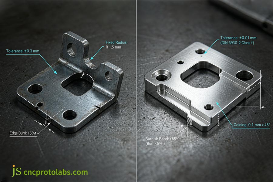
Figure 1: CAD-annotated comparison of standard vs custom metal stamping tolerances, contrasting general ±0.3 mm bounds with DIN 6930-2 Class f (±0.01 mm) precision.
Principles of Tooling and Wear Control
Tolerance variation in production involving multi-thousand cycles is attributed to tooling design and wear control:
- Standardized Universal Dies (Wear Accumulation): As a consequence of multiple manufacturing cycles using reusable tooling, wear is produced on the edge of the punch, which causes increased clearance between the punch and the die outside ±0.3 mm tolerance.
- Sub-Micron Tungsten Carbide Inserts: Custom dies incorporate tungsten carbide inserts (89-92 HRA) that maintain sharp cutting edges throughout millions of strokes without any dimensional deviation.
- Multi-Pass WEDM Finishing: The custom toolpaths create finish Ra 0.2 m with mechanical clearance of 1-2% of stock thickness.
- Closed-Loop In-Die Sensing: Laser micrometer placed on die plate measures incoming sheet thickness and controls mechanical stroke at speeds ≥600 spm.
How Does Metal Stamping Material Selection Impact Tooling Longevity?
Metal stamping material selection dictates die wear rates and forming accuracy. Standard catalog tooling is optimized for generic alloys like cold-rolled steel (SPCC) or standard aluminum (6061-O), exhibiting poor control over high-springback metals. Custom tooling integrates specialized springback compensation and hardened tool steel components (such as D2 or DC53) designed explicitly for exotic alloys, including beryllium copper, phosphor bronze, and high-strength stainless steels.
Alloy Limitations in Standard Stamped Parts
Standard stamped components depend exclusively on ductile alloys with known properties to reduce die wear:
- Standard Ductile Stock: Only available in low carbon steels (SPCC, DC01), soft aluminum (5052-H32, 6061-O)or free-cutting brass (H62).
- Application Demands: Devices for electromagnetic interference (EMI) screening, rigorous oxidation resistance, or biocompatibility demand high-performance alloys well above standard die limits.
- Specialty Alloy Requirements: Demanding environments necessitate full-hard stainless (301-FH), high-conductivity spring alloys (beryllium copper C17200, phosphor bronze C5191), or titanium (Grade 2, Ti-6Al-4V).
Physical Behaviors in High-Tensile Forming
To form hard metals like fully hard 301 stainless steel and beryllium copper, specially designed dies are required in order to consider three properties:
- Angular Springback: High Rp0.2 / E alloys will exhibit springback angle between 2° to 8°, whereas standard dies will create an angle of 93° to 98°.
- Overbending Compensation: Cavities are pre-compensated (grounded to 84. 5 for 5. 5 springback for example) to ensure true 90. 0 ° bends. (refer to our Sheet Metal Bending Parameters & K-Factor Guide).
- Anti-Galling Treatments: Punches use PM tool steels with a 2-3 μm PVD TiAlN coating (>3,000 HV, friction <0.2) to prevent cold welding over ≥1,000,000 cycles.
When Should Engineers Choose Low Volume Metal Stamping Over Custom Tooling?
Choosing between standard vs custom metal stamping during prototyping balances speed against tolerance fidelity. Below 1,000 units, low volume metal stamping using modular stamping tooling inserts or CNC laser-brake fabrication eliminates die CapEx. For complex features, single-station soft tooling verifies progressive repeatability before mass production.
Development Lifecycle Points: EVT, DVT, and PVT
Match tooling investment directly to your product development phase:
- EVT (10 - 200 Units / Fluid Design): Use fiber laser cutting and CNC press brake. Stay away from dies as hole locations and patterns change quickly.
- DVT (200–2,000 Units / Structural Testing): Deploy modular die holders or pre-hardened P20 soft tooling to test draw radii and springback. For bridge tooling trade-offs, see our Rapid Sheet Metal Prototyping vs Production Stamping analysis.
- PVT & Serial Production (>5,000 Units / Design Freeze): Invest in custom progressive Stamping Tooling to lock process (Cpk 1. 33) capability, and realize lowest piece costs, at speeds up to 600 spm.
3-Step Selection Gating Process
- Geometry & Tolerance Gate: When the component incorporates catalog shapes (such as washers, clips, brackets), having tolerances > ±0.2 mm, use standard stamped components.If tolerances demand < ±0.1 mm, select modular soft tooling.
- Stability Gate: If geometry is custom but unverified, route through CNC sheet metal fabrication to avoid the cost of die modifications.
- Volume Gate: Once designs freeze, route annual volumes > 10,000 units into custom progressive hard dies, keep runs of 1,000 to 5,000 units on modular bridge tooling.
For production die fabrication and high-volume runs, review JS Precision Metal Stamping Services for high-speed progressive manufacturing.
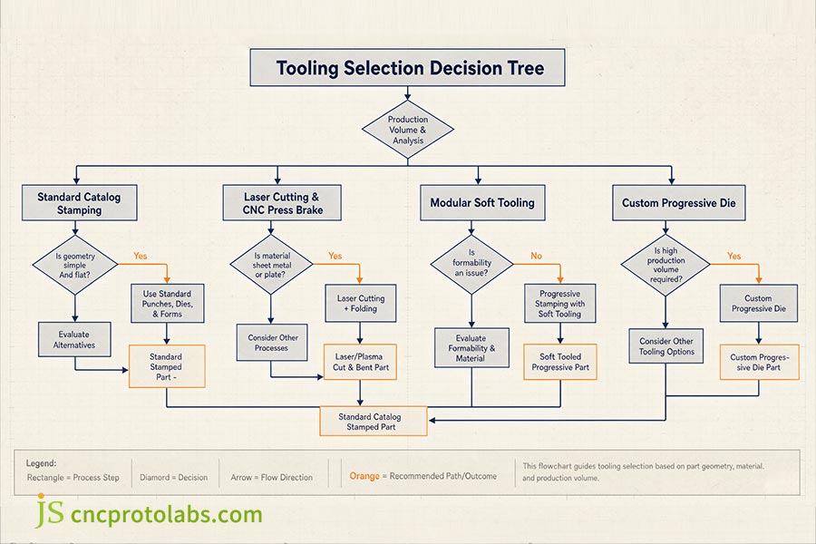
Figure 2: Engineering stamping tooling selection decision tree routing components by volume, geometry, and material between catalog dies, soft tooling, and custom progressive dies.
FAQ
Q1: What is the average lead time difference between standard and custom metal stamping?
Standard stamped parts ship in 24 to 72 hours from inventory or universal tooling. Custom metal stamping tooling requires 4 to 10 weeks for CAD tool design, CNC roughing, vacuum heat treatment, micro-wire EDM, manual bench fitting, and T0/T1 trial stampings.
Q2: Can standard stamping tooling support progressive forming operations?
No. Standard tooling only supports standalone, single-stroke press operations (e.g., 90° V-bending or blanking). Progressive stamping requires continuous carrier strips, dedicated pitch spacing, and sequential die stations engineered exclusively for a single part geometry.
Q3: How do standard vs custom metal stamping dies handle part revisions after production starts?
Standard stamped parts permit zero die modification, requiring a different catalog profile or mating part redesign. Custom stamping tooling supports localized engineering changes: wire EDM recutting or modular punch inserts accommodate hole shifts and clearance adjustments, while radical topology changes require station remachining.
Q4: What are the primary failure signs of low volume metal stamping tools?
Soft tooling fails primarily via abrasive edge wear. Critical indicators include sheared burrs exceeding 10% of sheet thickness, sidewall galling, and dimensional drift exceeding DIN 6930-2 Class M, signaling enlarged punch-to-die clearances that require immediate resharpening or insert replacement.
Q5: Is custom tooling economically viable for production runs below 5,000 parts?
Full-scale progressive custom tooling is not generally cost-effective under 5,000 pieces with NRE amortized over the run. Modular hybrid tooling can be cost-effective: standard master die shoes using custom wire-EDM inserts, or laser blanking all of the blanks combined with single station form dies.
Q6: How does strip layout optimization in custom stamping reduce total raw material scrap?
Custom progressive dies use nesting software to limit the skeleton edge margins to 1. 0-1. 5 times the sheet thickness. Interlocking or double-row nesting arrangements can achieve 75-85% raw material efficiencies compared to conventional stampings stamped from generic strip cutoffs at 35-45% scrap losses.
Q7: What is the standard burr height limit for precision custom metal stamping?
The burr height that is achievable in precision custom metal stamping is usually 5% to 10% of sheet thickness (absolute burr 0. 02 mm) for tight-tolerance terminals and clips. Common custom pressings can have 15% to 20% of sheet thickness burr height, though these are normally further buffed in a vibratory tumbling process or abrasive deburring.
Q8: Why does high-strength steel require dedicated custom dies instead of standard tooling?
High-strength steels exhibit severe elastic recovery, generating springback angles of 5° to 8°. Standard dies have fixed 90° cavities that cannot compensate for this rebound, causing punch chipping and dimensional failure. Custom dies integrate engineered overbending profiles (such as 84.5° cavities) and high-tonnage nitrogen gas springs to guarantee accurate final part geometry.
Summary
Choosing between standard stamped parts and custom tooling depends on volume, tolerance, and geometry:
- Select standard stamped parts for volumes <5,000 units and non-critical tolerances of ±0.2 mm to ±0.5 mm (DIN 6930-2 Class M) to avoid upfront die costs.
- Invest in custom tooling for tolerances down to ±0.01 mm (DIN 6930-2 Class f), high-tensile springback compensation, or continuous runs >10,000 units to minimize unit costs.
For complete fundamentals on sheet metal forming processes, die tooling capabilities, and design guidelines, refer to our comprehensive Sheet Metal Stamping Guide.
Evaluating tooling payback or verifying part manufacturability for an upcoming production run? Contact JS Precision Tooling Engineers for a complimentary tolerance feasibility review, CAD DFM analysis, and strip-nesting cost evaluation.

Disclaimer
The content on this page is for informational purposes only. JS Precision Services makes no representations or warranties, express or implied, regarding the accuracy, completeness, or validity of the information. It is the buyer's responsibility to determine specific technical requirements and request a formal parts quotation . Please contact us for more information.
Resource

