 English



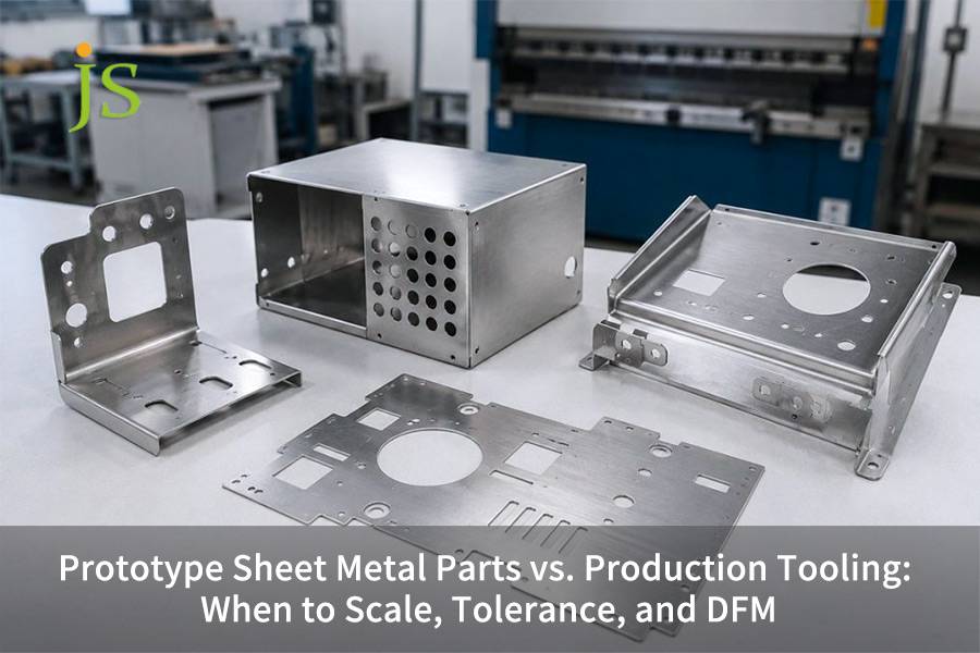

Prototype sheet metal parts are those manufactured without dies by laser cutting and CNC bending, typically used for cost-effective concept verification whereas, production tooling is high-speed stamping with hardened steel dies which reduces per-unit costs by 88% but at the same time the tooling costs are very high initially. The crossover of two methods usually comes to the annual volume of 1,500 units or the processing time of more than 8 minutes per unit.
The next paragraph deals with a convergence study on the tolerance control, interpreting DFM rules and ROI calculation models through the use of real machining data from JS Precision.
Quick Comparison: Prototype Sheet Metal Parts vs. Production Tooling
|
Dimension |
Prototype Sheet Metal |
Production Tooling |
|---|---|---|
|
Typical Process |
Laser/waterjet cutting + flexible CNC bending |
Progressive die / compound stamping die |
|
Tooling NRE |
$0 – $500 (soft jig only) |
$5,000 – $50,000+ (hardened steel die) |
|
Linear Tolerance |
±0.15mm to ±0.30mm |
±0.02mm to ±0.05mm |
|
Angular Tolerance |
±0.5° to ±1.0° (springback affected) |
±0.15° to ±0.25° (die coining) |
|
Economic Batch Threshold |
1 – 1,500 pcs/year |
> 1,500 – 5,000 pcs/year |
|
DFM Focus |
Avoid multiple tight bends, unify inside radius |
Reserve strip carrier, avoid punch stretch zone |
Data sources: ISO 20457:2018 tolerance classification. JS Precision 2025 project cost database.
Key Conclusions
- Crossovers of Investment: With annual demand over 1,500 units or processing time over a unit takes more than 8 minutes, the cost of amortized tooling is lower than the labor or machine-hour costs of using laser bending.
- A Gradual Tolerance Increase: The global ±0.05mm tolerance level is not required at the prototype stage, rather, use localized CNC secondary milling to achieve high precision in holes and mating features.
- From Rule to Action: The minimum edge distance requirement from the hole for laser cutting (2.0 x T) is to be raised to 2.5 x T in stamping dies to prevent punch wear as far as possible.
- Springback After Stamping: Stamping work results in work hardening that can bring an 8-12% increase in the rate of spring back when compared to CNC bending, tooling design must account for these allowances in compensation.
Prototype vs Production Sheet Metal: Core Manufacturing Differences Explained
Prototype vs production sheet metal works are usually laser cutting and CNC bending processes to be tool-free so they can be delivered quite quickly. Production tooling uses hardened D2 or SKD11 steel dies to produce dimensionally consistent parts with low per-part cost due to full-contact forming.
Impact of the Laser Heat-Affected Zone (HAZ) on Stamped Edges
Based on experiments carried out at Precision Laboratory, the depth of HAZ at 2.0mm thick 6061-T6 aluminum after using the laser is about a twentieth of a millimeter. It has already made an aluminum harder in that area from 15 to 20% which can cause micro-cracking during the next bending
- Influence of HAZ on edge quality: An 0.12mm HAZ depth leads to the different hardness along the bending edge causing micro-cracks in case the bending radius is less than 2.0T. For prototype sheet metal parts, this phenomenon is easily overlooked during the prototype stage, but it must be strictly controlled when entering mass production.
- Stress distribution differences: Three-point bending of CNC devices results in localized stress points. Still, full-contact forming through stamping tools even stress distribution throughout the bend area, which results in springback reduction by 40%.
The ISO 9013:2017 document states: Classifications of quality levels for thermally cut surfaces shall be based on the cut surface roughness (Rz), for sheet metal parts used generally, the Rz should not exceed 50μm.
To be compliant with this requirement, JS Precision deburrs critical edges after laser cutting, ensuring that Rz≤ 50 μm. Besides that, the change from one step to the other lowers the scrap percentage from 25 (laser cutting) to 8 (progressive die layout), greatly enhancing the use of materials. The sheet metal fabrication service route chosen gives a smooth transition from product trial to full-fledged manufacturing.
Comparison of Processing Cycles and NRE Costs
- Prototyping phase: Each unit will go through the processing cycle in 8 to 15 minutes, first-time costs will be from 0 to 500.
- Mass Production Stage: Die cycle time is 6 to 15 seconds, first-time costs range from 5,000 to 50,000.
Making prototypes is custom hand craft, fast but expensive, industrial die cutting is like conveyor belt, once everything is done you get very cheap parts.
Want to know which manufacturing method will be the most suitable for your project of sheet metal parts?Sending the drawings to JS Precision free and ask for a comparison.
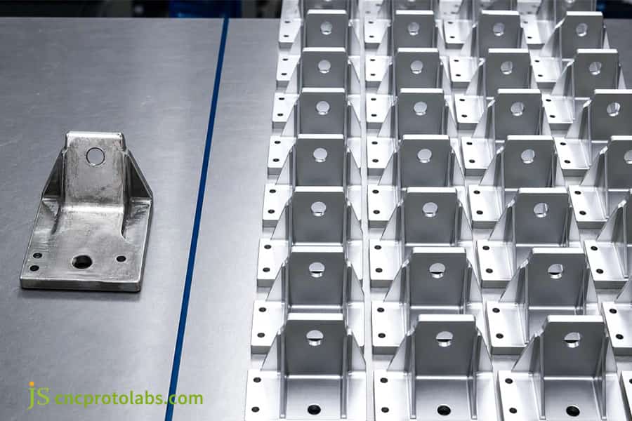
Figure 1: Comparison of prototype and production sheet metal parts on a surface.
When to Scale from Sheet Metal Prototype Fabrication to Production Tooling?
Shifting from sheet metal prototype fabrication to tooling for production is based on the balance between NRE of the die, and labor cost, per piece. The point of change happens when annual volume reaches 1,500 pieces or the cumulative single-piece processing time exceeds the time required for amortization of the die.
Break-even Calculation Formula
The formula for calculating the transition threshold is as follows:

Mentioning a metal housing made of 1.5mm sheet material SPCC, a unit price comparison is given based on the manufacturing volume:
|
Annual Volume (pcs) |
Prototype Unit Cost |
Production Unit Cost |
Total Cost After Tooling Amortization |
|---|---|---|---|
|
100 |
$45.00 |
$7.80 |
$507.80 (incl. $500 soft tool) |
|
1,000 |
$45.00 |
$7.80 |
$8,280 (incl. $500 soft tool) |
|
5,000 |
$45.00 |
$3.20 |
$21,000 (incl. $5,000 hard die) |
|
20,000 |
$45.00 |
$2.50 |
$55,000 (incl. $5,000 hard die) |
Data source: JS Precision 2025 sheet metal mass production database statistics.
Feasibility of Soft Tooling as an Intermediate Solution
- Aluminum Soft Tooling: Appropriate for a quantity of 500 to 2,000 pieces. Compared with hard tooling, the NRE (Non-Recurring Engineering) costs of soft tooling are 60% less. Soft tooling is the preferred and temporary means of customers seeking rapid sheet metal prototyping service.
- Cost Performance: A total cost of 8,280 for soft tooling versus 13,200 for hard tooling can be achieved with a production volume of 1,000 units which saves 37% from soft tooling. When manufacturing your custom sheet metal fabrication, production processes can be varied as your production amount.
Plain-English Summary: Up to 1,500 parts, laser cutting and bending are cheaper, but below this level, the saving on each unit is so high that it rapidly offsets the tooling cost.
If you are wondering, When is it worth financially switching to your other method? let JS Precision provide a free cost-modelling analysis. You just input an annual production volume to have a precise calculation of your break-even point.
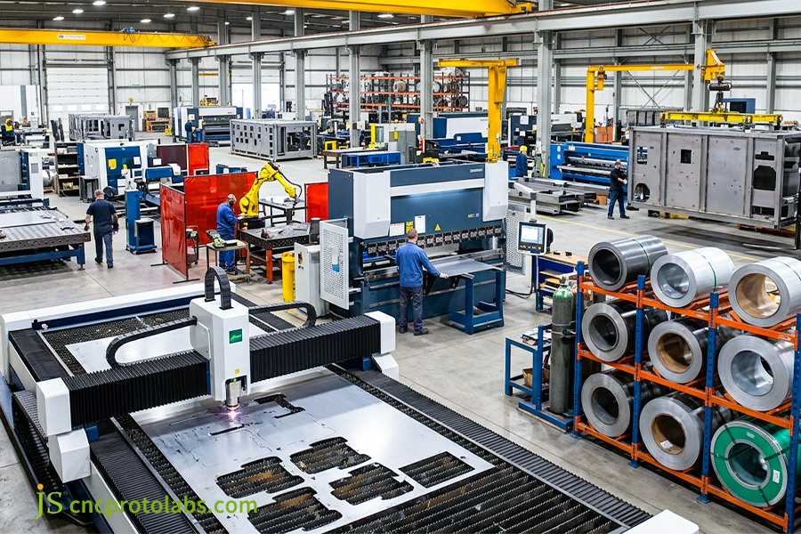
Figure 2: Large factory floor with machines for sheet metal fabrication.
Tolerances for Sheet Metal Prototype Parts vs Production Tooling
Tolerances for sheet metal prototype parts range from ±0.15 to ±0.2mm. Then again, production molds are able to maintain a tolerance of ±0.02mm. In case of key mating surfaces, laser cutting pilot holes combined with secondary CNC milling would be the ideal procedure.
Cost Pitfalls of Improper Tolerance Specification
- Global Tolerance of ±0.05mm cost: If you add a global Tolerance of ±0.05mm to your drawing this will result in a 3-fold increase in cost, because multiple CNC Finishing Passes are required. With prototype sheet metal parts it is advisable to tight the tolerance only on those surfaces that are critical mating surfaces.
- Standard Tolerance Grades: ISO 2768 - mK (medium Tolerance) is good for Prototypes, whereas ISO 2768 - fH (Fine Tolerance) is a good choice when it comes to producing a big quantity of parts.
ISO 2768-1:1989 explicitly states: Linear and angular dimensions that are not specified with individual tolerance values should be given limit tolerances as the tolerance classes f,m,c or v, this is for general dimensions on stamping processes.
To follow ISO 2768-1:1989 standard precisely, JS Precision uses a system of tolerancing at different levels for features where tolerances have not been specified when examining custom sheet metal fabrication drawings, assisting them in cutting production costs by 30%.
Factors Influencing the Springback in Bending
- Tensile Strength Variation: A ±10 MPa fluctuation in the sheet metal tensile strength results in a bend angle change of ±0.4 degrees.
- Grain Direction Effect: Rolling direction bend is accompanied by a 0.3mm bend allowance variance whereas the cross grain bend gives a 0.1mm variance.
JS Precision's Angle Real-Time Compensation System
Based on JS Precision empirical data, the deployment of a laser angle measurement feedback system makes it possible to conduct real-time angle compensation while bending resulting in a tolerance range of about ±0.25°. This is 60% higher precision relative to conventional methods and this system assures a match between first prototypes and mass-produced parts.
Do not aim at achieving tight tolerance mostly part during the prototype phase, you can only focus precision machining on the mating features that are critical. So you can cut the costs by 70%.
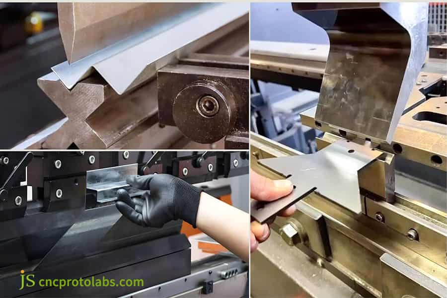
Figure 3: Close-up of sheet metal bending process in machinery.
3 Essential DFM Rule Changes for Scaling Prototype Sheet Metal Parts
To go from prototype sheet metal parts to mass production needs changes in factors like the bending distance to the hole, bend inside radius, relief slot shape that is done in one go, so these prototype deflection rules are translated to progressive die-strip layout and punch wear optimization guidelines.
DFM Rule Comparison Table
|
DFM Parameter |
Prototype Laser Bending Requirement |
Progressive Die Requirement |
Reason for Change |
|---|---|---|---|
|
Hole-to-Bend Distance |
D ≥ 2.0 × T + R |
D ≥ 2.5 × T + R |
Prevent hole pull, extend punch life |
|
Inside Bend Radius |
R = 1.0 × T (standard tool) |
R = 0.5 × T (coining station) |
Higher forming force available |
|
Relief Slot Shape |
Rectangular slot, width 1.5 × T |
Arc transition slot |
Reduce stress concentration, prevent cracking |
Bridge Design in Progressive Die Strip Layout
- Effect of Carrier Web on Burrs: Incorrect placement of bridges results in leftover tie-off burrs on edges of parts of up to 0.15mm tall, applicable with custom sheet metal fabrication where it influences the end quality of parts.
- JS Precision DFM review process: For the rapid sheet metal prototyping service, the engineering group is able to check for the bridge positions in advance and potentially lower the burr height up to 0.05mm.
Some design practices that have worked well in the prototyping phase might cause mass production problems, holes too close to a bend line may stretch and deform, while improper relief slot shapes lead to short die life.
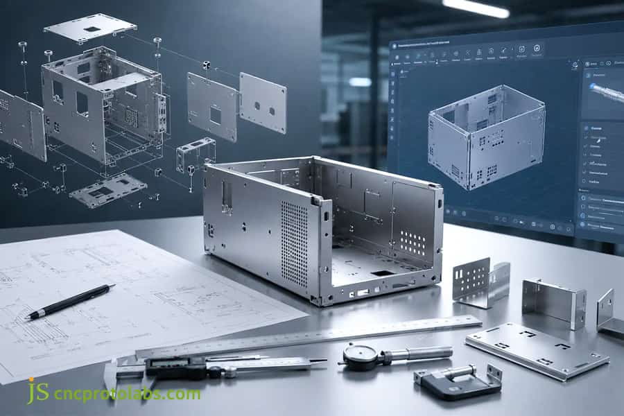
Figure 4: Designing custom sheet metal fabrication with CAD software.
JS Precision Case Study: Scaling 5,000 Custom Sheet Metal Enclosures
Sheet metal fabrication service is able to demonstrate their competence by maintaining the batch consistency. This case study illustrates how JS Precision assisted a European telco customer in increasing the volume from 50 units per year to 5,000 electrical enclosures.
Client Challenges
One of our European telecommunications clients had the challenge of increasing production of heat-dissipating electronic control cabinets (which were made of Al 5052-H32 2.5mm) from 50 to 5000 annually. The first prototype was done by laser cutting and manual bending, the problem was that 12 countersunk holes with high density were not coaxial enough to meet the blueprint tolerance of ±0.03mm, and misalignment resulted from fastening the top cover as it got a lot of the cumulative bending errors.
JS Precision Solutions
- DFM Structure Redesign: By turning four 90 bends into stamped forming ribs we were able to eliminate the buildup of errors that could happen from successive forming actions.
- 8-Station Progressive Die Design: A coining station was added to form the countersunk holes, removing the need for secondary CNC drilling operation.
- Springback Compensation Algorithm: To overcome the springback effect which occurs naturally in AL 5052-H32, the punch and die have been pre-compensated by +1.2°. Custom sheet metal fabrication approach was a great help in improving production efficiency.
Lessons Learned
From our experience with the JS Precision JSP-SMT-2025-017 project, a cracking defect was detected at station five during a T0 tool die trial as it turned out the hardening through working of the material AL 5052-H32 during continuous stamping had not been taken into consideration. The technical team successfully got rid of the cracking defect by regulating the stamping oil viscosity and also enlarging the forming radius from 2.0mm to 2.8mm.
Final Quantifiable Results
- Time for a processing cycle per unit: The time for producing one unit went from 14 minutes (prototype) down to 12 Seconds (progressive die).
- Cost for production per unit: From approximately 68.50 to approximately 7.80 the costs were reduced.
- Cpk of dimensions: Cpk of the dimension was improved from 1.53 to 1.67.
Is your sheet metal project facing challenges when you try to switch from prototyping to the stage of mass production? Upload all your 3D CAD Drawings and contact JS Precision to get a free DFM Analysis and a Quotation for mass production.
4 Costly Pitfalls When Scaling Sheet Metal Prototype Parts to Production
When moving sheet metal prototype parts into mass production, you can save money by not being over-specifying your drawings, not considering strength as a constant factor between lots of a same metal, not considering coatings can come in various thicknesses, and not deciding about hard tooling way too soon.
Incidence Rates and Additional Cost Proportions for the Four Major Cost Pitfalls
|
Cost Trap |
Occurrence Rate in Mass Production Projects |
Percentage of Total Project Cost |
Average Fix Time |
|---|---|---|---|
|
Coating thickness neglect |
38% (15/40 projects) |
8%–12% |
1–2 weeks |
|
Grain direction ignorance |
23% (9/40 projects) |
5%–10% |
2–3 weeks |
|
Premature hard tooling commitment |
15% (6/40 projects) |
20%–35% |
4–8 weeks |
|
Automation gripping omission |
43% (17/40 projects) |
3%–6% |
2–4 weeks |
Data source: JS Precision retrospective analysis of 40 sheet metal mass production projects (2025).
Pitfall 1: Neglecting Coating Thickness
- Powder coating dimensions (window size): Proposed to increase by 60-100μm, does not allowing for this space so the PEM self-clinching nuts to be assembled. With coating thickness one should be taken into consideration during the sheet metal prototype fabrication.
- Electro-galvanizing thickness: 8-12μm, net large hinge fit clearance calls for an increase of 0.02mm.
Pitfall 2: Ignoring Material Grain Direction
- Bending along the rolling direction: Causes micro-cracks, the bending radius must be ≥ 2.5×T.
- The nesting requirements due to mass production: All nesting patterns need to keep the angle of 45° and 90° about the direction of grain. These automatic sheet metal fabrication service can keep the grain line direction for you in their nesting stage.
Pitfall 3: Committing to Hard Tooling Too Early
- Risk: manufacturing the hard tooling due to be ready if design fails the 1,000hr salt spray or environmental test. Design changes in a scrapped tooling.
- Advice: carry out testing of the design, on soft tooling or prototypes, before making an expensive hard tooling investment.
Pitfall 4: Overlooking Automated Handling
- Missing location holes: the workpieces, which were produced mass, the mass production demands location holes (datums) and flat suction regions for robotic arm to handle.
- The process at JS Precision: Use location hole configurations at the prototype stage, so all prototypes will have the same feature of the mass production fixture.
The surface finish issues that are brushed aside in development can ruin your process in the end. Taking into account the thickness of surface finish, orientation of the material grain and the automation needs can eliminate 80% of the problems in mass production.
Interested in helping your group reduce expenses in mass production? Send your sheet metal drawings to JS Precision and our engineering staff will provide you with an entire DFM optimization suggestion in 2 hours.
Why Choose JS Precision as Your Custom Sheet Metal Fabrication Partner?
Established with 15 years of expertise in sheet metal engineering precision, JS Precision brings solutions as simple as delivery 3D models to progressive die stamping of several thousand parts. Finding the perfect custom sheet metal fabrication partner is dependent on machinery capability, quality inspection, and technological support speed.
JS Precision Delivery Assurance
- Equipment Capacity: We offer the use of 10 kW fiber laser cutters, AMADA press brakes, and stamping presses ranging from 160T to 400T that allow the smooth change from speedy sheet metal prototyping through to the volume production.
- Quality Control: By combining Hexagon CMM machines with full-process SPC monitor it is possible to achieve linear tolerances that remain steady from one batch to the next (0.02mm). Every sheet metal parts batch will include a detailed inspection report.
- Technology & Efficiency: Gloria Wu, Technical director, and her team are capable of providing DFM evaluations and giving BOM-based quotes in as fast as 2 hours, thereby helping to shorten the time-to-market by 30%.
FAQs
Q1: What is the typical lead time for prototype sheet metal parts vs production tooling at JS Precision?
Prototype sheet metal parts are laser cut and CNC bent.Lead time to drive these parts is 3-5 working days. Lead time for to produce tooling (progressive die design manufacture T1 sample review/approval) is 3-5 weeks.
Q2: How does material selection impact the cost of sheet metal prototype fabrication?
Typically, low processing cost materials are standard materials such as SPCC and AL 5052.The cost of using SUS 316L as sheet metal prototype is 20% to 40% more expensive.
Q3: Can JS Precision use the same CAD files for both prototyping and mass production?
STEP or IGES file are accepted right away.Our engineers team also perform a second DFM review to fineadjust the bend deduction and hole pitch before mass production.
Q4: What are the primary factors affecting a Custom Sheet Metal Fabrication quote?
The quotation for custom sheet metal fabrication is determined by four core factors: material type and thickness, total processing hours (cutting length, bending frequency, welding process), surface treatment requirements (spraying, anodizing), and the number of orders with amortized fixed costs.
Q5: How do you handle tolerance stack-up during high-volume sheet metal fabrication service?
In production, the company qualifies the assembly by controlling all the important tolerances down to ±0.03mm using the optical positioning datums with subsequent SPC monitoring.
Q6: Is soft tooling a viable middle ground between prototypes and hard production tools?
Yes.Soft tooling is good for yearly volume of 500-2000 and it results in 60% reduction of NRE (tooling) cost versus hard steel dies and it has better dimensional stability than manual bending.
Q7: What surface finishes are available for rapid sheet metal prototyping service?
To complement the speedy sheet metal prototyping service of JS Precision, additional surface treatment is available including, sand blasting anodizing powder coating and electro galvanizing.
Q8: How can I request an instant quote for my prototype sheet metal parts from JS Precision?
Upload your 3D CAD Models (STEP, STP) and Tolerance 2D Drawings (PDF) and submit your RFQ for JS Precision's Engineering Department to reference in as little as 2 hours.
Summary
Switching from prototype sheet metal parts to large scale stamping needs you to re-design specs, tolerance strategy, and total cost management (Total Cost of Ownership) of sheet metal parts. You can lower your per unit production cost with stamped parts by having realistic tolerance ranges for parts as a starting point, being receptive to changes in design to be manufactured (DFM) for stamping dies, and gradually introducing progressive die technology at an economic crossover point where cost effectiveness is assured.
Whether you are developing a new sheet metal product or improving an established die stamped mass production plan, JS Precision brings technical assistance at every step of manufacturing, from prototyping to die stamping at larger volumes. For more details submit your 3D CAD drawings so that JS Precision engineering can prepare, within a couple of hours (at no charge), a DFM assessment report and overall project quote.

Disclaimer
The contents of this page are for informational purposes only. For JS Precision Services, there are no representations or warranties, express or implied, as to the accuracy, completeness, or validity of the information. It is the buyer's responsibility to identify specific technical requirements and request a formal parts quotation. Please contact us for more information.
JS Precision Team
Custom manufacturing solutions. With over 15 years of experience serving more than 1,000 customers, we specialize in high-precision CNC machining, sheet metal fabrication, 3D printing, injection molding, and metal stamping. Having successfully delivered over 300,000 precision parts, we maintain a 99.2% on-time delivery rate across all custom projects.
Our facility is equipped with over 100 state-of-the-art 5-axis machining centers and is ISO 9001:2015 certified. We deliver fast, efficient, and high-quality manufacturing solutions to B2B clients across 150 countries. Whether you require low-volume prototyping or large-scale customization, we support your project with lead times as short as 24 hours. Choose JS Precision for unparalleled efficiency, quality, and professionalism.
To learn more or submit your RFQ, visit our website: www.cncprotolabs.com
Resource

