English



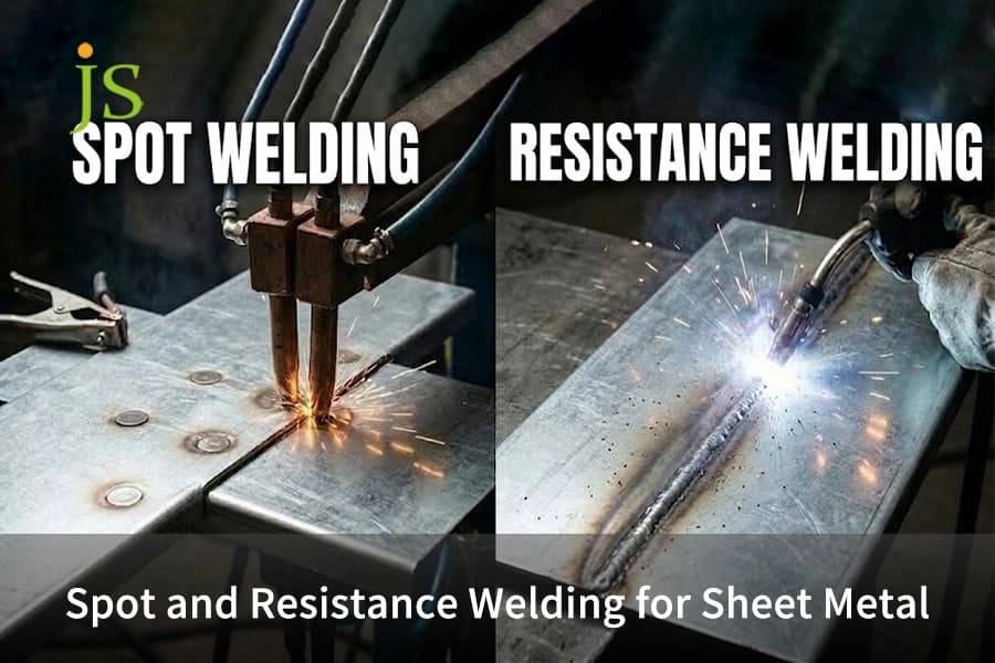

Resistance welding for sheet metal fuses overlapping plates using electrical resistance heat (Q = I²Rt) and clamp pressure without filler wire or shielding gas. This process is designed for sheet metals with gauges ranging between 0.5mm and 3.0mm, taking only less than 0.25 second to complete each cycle.
Sheet Metal Welding Process Quick Selection Chart
Resistance spot welding is used in lap joints of structures, seam welding in leak-proof vessels, projection welding in stamped hardware, and MIG arc welding where the thickness of the plates exceeds 3.0 mm or gap exceeds 0.8 mm.
| Process Type | Thickness Range | Joint Configuration | Cycle Speed | Hermetic Sealing | Relative Cost per Joint | Primary Failure Risk |
| Resistance Spot Welding (RSW) | 0.5 mm to 3.0 mm | Overlapping lap joint | 0.05 to 0.25 s | No (discrete nuggets) | Lowest ($0.005 to $0.015) | Molten blowout, current shunting |
| Resistance Seam Welding (RSEW) | 0.3 mm to 2.0 mm | Continuous overlapping seam | 0.5 to 3.0 m/min | Yes (up to 0.3 MPa pressure) | Medium ($0.08 to $0.20/m) | Wheel electrode wear, surface scoring |
| Resistance Projection Welding (PW) | 0.8 mm to 4.0 mm | Embossed dimples, weld fasteners | 0.1 to 0.4 s (multi-point) | Partial (ring emboss only) | Low ($0.010 to $0.025) | Incomplete dimple collapse |
| MIG Arc Welding (GMAW) | 1.5 mm to 12.0+ mm | Butt, tee, corner, lap | 5 to 25 s per seam | High ($0.35 to $0.80/joint) | High ($0.35 to $0.80/joint) | Thin sheet burn-through, plate warpage |
What Is Resistance Welding for Sheet Metal?
Resistance welding for sheet metal electric current flows through the workpiece while the sheet metal is compressed by the electrodes to heat melting points on contact surfaces. The family includes resistance spot welding, seam welding and projection welding.
How Heat Builds at the Sheet Interface
Large current flow in copper tips results in localized heating at the point of maximum sheet contact resistance. The clamp force holds the liquid nugget trapped inside the joint, removing the need for filler wire flux shielding gas or panel warp.
Standard Machine Setups in the Workshop
Three standard machines set-ups operate in shops:
- Pedestal Spot Welding Machines: Stationary arms used for single spot welding on brackets and sheets.
- Continuous Seam Welding Machines: Copper wheels moving around a seam, which create air-tight tanks through motor operation.
- Press-Type Projection Welding Machines: Press platens, which collapse several projections or weld nuts in one stroke.
How Does Resistance Spot Welding Work on Industrial Sheet Metal?
In resistance spot welding, the sheets of metal are held between the copper tips and 4,000 to 15,000 A of current is passed through the junction. It creates a molten weld at the interface in 0.05 to 0.25 sec and 1.5 to 5.5 kN pressure without any filler.
The Four Steps in the Spot Welding Process
Every weld consists of four fast steps:
- Squeeze Step: Tips squeeze together based on pre-set pressure to position sheets and close any openings.
- Welding Step: The current flows through the contact surfaces with high amperage to form the nugget.
- Hold Step: Current stops while the tips continue holding to cool the nugget through water-cooled copper tips.
- Off Step: Tips separate to transport the joint to another spot.
Weldability of Metals for Common Sheet Alloys
The welding conditions change in relation to electrical resistance and heat conductivity according to ISO 18278-2 Resistance Welding Specification:
- Low-Carbon Mild Steel (SPCC / Cold Rolled Steel): It is the easiest metal to perform spot welding on by utilizing Class 2 copper chromium electrodes without electrode redress for many cycles.
- Austenitic Stainless Steel (304 / 316): High resistance makes this metal need 30% to 50% lower current and increased clamping force to avoid surface burning.
- Aluminum Alloys (5052 / 6061): Heat losses make this metal need three times more current, Class 1 copper zirconium electrodes, and wire brushing within 24 hours.
Spot vs Seam vs Projection Welding: Which Resistance Method Fits Your Part?
In spot vs seam vs projection welding, spot welding is a low-cost option for structural brackets, seam welding ensures a leak-proof tank, and projection welding includes collapsing stamped dimples to fuse multiple points at once without damaging the faces of the part.
Differences on Shop Floor and Limitations
Process is dedicated to certain parts shapes:
- Spot Welding Characteristics: Creates discrete circles on lap joints used for open brackets, but is incapable of forming air-tight or fluid tight seal.
- Seam Welding Characteristics: Roll copper wheels over edges of sheets and create an air-tight seal that can withstand 0.3 MPa of internal pressure.
- Projection Welding Characteristics: Current passes through stamped circles or weld nuts and welds several points simultaneously without making deep tips.
Assembly Alternatives: Comparison between Spot Welding and Mechanical Fitting
Design teams compare resistance joining directly with fasteners in spot welding vs riveting.
Riveting needs pre-punched holes, purchased hardware, and manual line labor. Spot welding joins parent sheets in a fraction of a second, with no added hardware expense and zero dead weight. Riveting is still required when bonding pre-painted panels, non-conductive components, or incompatible materials like aluminum-to-carbon fiber when welding heat, destroys, coatings, or causes galvanic corrosion.
Process Comparison: Spot vs Seam vs Projection Welding
| Evaluation Metric | Resistance Spot Welding (RSW) | Resistance Seam Welding (RSEW) | Resistance Projection Welding (PW) | Blind Riveting (Mechanical) |
| Airtight Joint Sealing | Non-sealed (spaced nuggets) | Hermetic seal (IP67 / 0.3 MPa rating) | Non-sealed (standard) / Sealed (ring emboss) | Requires liquid sealant or rubber washers |
| Typical Cycle Speed | 0.05 to 0.25 s per spot | 0.5 to 3.0 m/min continuous feed | 0.1 to 0.4 s (multiple spots at once) | 2.5 to 6.0 s per manual rivet |
| Cosmetic Indentation | Visible mark (5% to 15% sheet gauge) | Continuous wheel track | Little to no trace on the flat side | Visible raised or countersunk rivet head |
| Primary Process Failure | Current shunting or edge blowout | Heat warping along long, thin edges | Incomplete dimple collapse or cold weld | Mandrel break-off, loose holes, corrosion |
For sheet assemblies in which you are considering spot vs. seam vs. projection welding: use spot welding for general structural frames so you can keep the tooling costs down, specify seam welding where you need to contain fluids, specify projection welding for fast multi-point stampings with clean cosmetic faces, and use riveting where you are joining pre-coated or dissimilar materials.
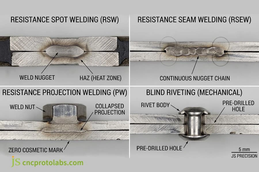
Metallographic macro-sections displaying weld nugget fusion, continuous seam hermetic seals, projection collapse, and mechanical riveting.
Resistance Welding vs MIG Welding: When Should You Automate for Sheet Metal?
Resistance welding vs MIG welding is influenced by the gauge of metal, fit-up, and volume. Resistance Welding does not require gas, eliminates burn-through, and reduces thermal distortion to 80% when the gauge of metal is less than 3.0 mm. MIG welding still stands out when there are larger gaps of more than 0.8 mm. When the volume exceeds 5,000 pieces per year, spot welding is automated.
Resistance Welding vs. MIG Arc Welding Comparison
There are three shop disadvantages of MIG arc welding on sheets below 2.0 mm thick:
- Heat Distortion and Wavy Sheets: A linear arc heat distorts thin sheet. Standard MIG vs TIG vs Stick welding processes provide superior gap-bridging over resistance joints when parts are over 3. 0mm and need deep structural joints.
- Additional Grinding and Cleaning: MIG welds have a raised bead and some spatter that assembly workers have to grind flat before painting, while spot welds produce only a slight rounded-tip appearance.
- Fit Up Tolerance for Welding: Resistance welding depends on sheets to touch cleanly at less than 0. 15 mm. For more slack in the fit-up, each insertion must compare the laser vs MIG welding strength for structural enclosures without heat warp.
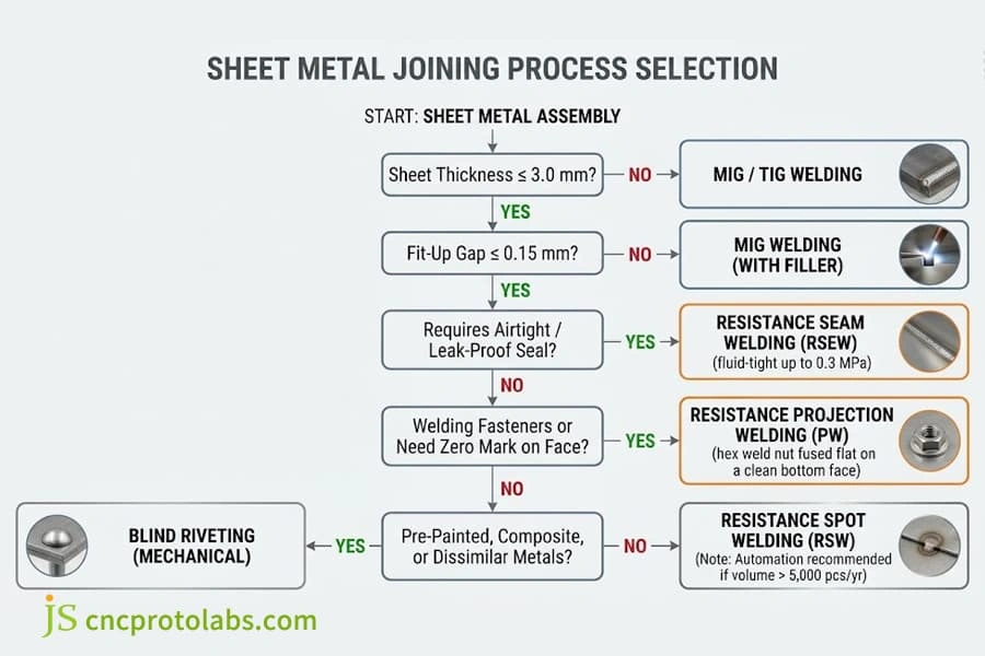
Engineering selection decision tree matching sheet gauge, fit-up gaps, and hermetic requirements to optimal joining methods.
Integrating Automated Spot Welding Cells
Manual guns lead to fatigued operators and tilted tip contact. By adopting spot welding automation, you can ensure stable production using four hardware upgrades:
- Medium-Frequency Inverters (MFDC): These operate at 1,000Hz and consume 30% less electricity while moving current in a millisecond.
- Servo Weld Guns: These electrically-driven welding guns clamp tips gently without pneumatic hammer blows, reducing surface marks by half.
- Robotic Tip Cutters: Automatic cutters re-form mushroomed copper tips to blueprint shape in less than five seconds every 250 to 400 welds. For high-speed lines, comparing resistance cell performance to automated laser vs manual TIG welding allows teams to establish the ideal balance between cycle time and equipment capital cost.
- Adaptive Power Controllers: Real-time feedback auto-adjusts power before a spark blowout happens.
How to Design Resistance Welding Parts: Nugget Size, Parameters, and Cost?
Weld sizing of resistance welding parts the right flange widths, edge margin, and pitch weld to prevent edge blowouts, and current shunting. Target spot weld nugget size / parameters are sized so that the strength of the resistance weld joint shear is equal to the parent metal to control the resistance welding cost per weld in mass production below $0.015.
Basic DFM Rules for Sheet Metal Stampings
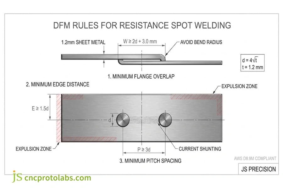
Ignoring electrode room and liquid metal expansion leads to edge blowouts and scrap parts:
- Minimum Flange Overlap: The flanges should hold the copper tip without sinking into the inner sheet bend radius. The flange length needs to be twice the nugget diameter plus 3.0 mm.
- Minimum Edge Margin: Spot welding too near the edge causes hot metal blowouts because of clamp pressure. The distance from the center of the nugget to the edge of the sheet needs to be 1.5 times the nugget diameter.
- Minimum Pitch Spacing: If two spots are too close to each other, weld current will steal from the cold nugget nearby instead of forming a new one. It is called current shunting. Keep the pitch spacing as 3 times the nugget diameter.
AWS D8.9M Weld Nugget Diameter and Strength Table
As per the AWS D8.9M Sheet Welding Standard, desired nugget diameter must be four times the square root of sheet thickness. For two dissimilar gauges, consider dimensions based on the thinner gauge sheet.
|
Sheet Gauge |
Target Nugget Diameter |
Minimum Flange Width |
Minimum Weld Pitch |
Low-Carbon Shear Strength |
|
0.8 mm |
3.6 mm |
10.0 mm |
12.0 mm |
3.2 kN |
|
1.0 mm |
4.0 mm |
11.0 mm |
14.0 mm |
4.5 kN |
|
1.2 mm |
4.4 mm |
12.0 mm |
16.0 mm |
5.8 kN |
|
1.5 mm |
4.9 mm |
13.0 mm |
18.0 mm |
7.6 kN |
|
2.0 mm |
5.6 mm |
15.0 mm |
22.0 mm |
11.2 kN |
|
2.5 mm |
6.3 mm |
17.0 mm |
26.0 mm |
15.5 kN |
Nuggets should be within ±0.2 mm of design diameters. Weld pitch needs to be large enough to avoid electrical current bypass. At the beginning of each shift, destructive peel tests must be conducted to ensure button pull-out failures are ductile.
Shop-floor welders test weld strength with destructive peel tests: Place a welded coupon in a vise and peel the sheets apart. An approved weld will leave a full round button of metal on the mating sheet (Button Pull-Out failure). Flat joint shearing shows a too-small cold weld.
Shop Floor Case Study: Conversion of Stamped Enclosures from MIG to RSW
Production run of 1.2 mm SPCC chassis by JS Precision involved welding of internal stiffener channels to the outer covers. The initial design called for 16 stitches MIG welds, which created 1.8 mm of diagonal warpage and took 12 minutes for post-weld grinding.
Our engineering team transitioned the assembly to automated resistance spot welding:
- DFM Tooling Change: Extended stiffener return flange from 8.0 mm to 12.0 mm as per 2d + 3.0 mm rule for 4.4 mm diameter nugget size.
- Weld Schedule Parameters: Applied 8.8 kA current, 2.8 kN electrode force, and 12 cycles of weld time with Class 2 copper-chromium tips.
- Quality & Cost Outcome: Diagonal warpage reduced from 1.8 mm to below 0.2 mm, making unnecessary manual straightening and bead grinding. Assembly time decreased from 14 minutes to 38 seconds per chassis with direct reduction in fabrication cost by 62%.
Cost per Weld Breakdown
In automated cells, the cost of direct labor per weld ranges from $0.005 to $0.015:
- Electricity Cost: Electrical power is applied for 100 to 250 milliseconds, consuming 0.003 to 0.008 kilowatts-hour and costing less than $0.0015 per hit.
- Copper Tip Wear: Copper caps are priced at $4.00 to $8.00 each, providing 20,000 to 50,000 welds when the tips are properly dressed and costing about $0.003 per hit.
- Machine Time: Robot time (0.8 to 1.5 seconds per spot), maintenance, and depreciation of equipment comprise the rest of the cost. For manufacturing cost comparison, review our welding services cost breakdown.
FAQs
How strong is spot welding, and is spot welding strong enough for heavy-duty assemblies?
When determining how strong is spot welding, a qualified 4.5 mm nugget on 1.2 mm steel resists over 5.8 kN shear strength according to AWS standards. The base metal fails in tension before the weld joint fails in shear, confirming that joints are spot welding strong enough for vehicle chassis, frames, and heavy HVAC cabinets.
Can aluminum sheet metal achieve reliable welds using resistance welding processes?
Yes. But aluminum needs 25,000 to 45,000 A from medium-frequency direct current (MFDC) inverters and Class 1 copper-zirconium electrodes because it has high thermal conductivity and an oxide layer (Al2O3). This material must be cleaned up within 24 hours prior to welding to avoid surface blowout.
What causes surface expulsion and deep indentation in precision resistance welding parts?
Surface blowout and tip dents greater than 10% of sheet thickness in resistance welding parts is because of insufficient clamp pressure, dirty sheets, or too much current flow. Tips of electrodes that are tilted by more than 0.5° angle and rounded tips cause concentration of heat and blow out molten metal.
What are the compromises in spot welding vs riveting manufacturing of sheet metals?
Comparing spot welding vs riveting balances tooling against hardware expense. Spot welding costs under $0.01 per point, adds zero weight, and needs no hole prep. Riveting costs $0.05 to $0.15 per fastener, but joins painted panels, dissimilar metals, and blind assemblies.
What factors dictate the resistance welding cost per weld in production?
Baseline resistance welding cost per weld in automated runs is between $0.005 and $0.015. Three driving cost factors are: power (0.005 kWh/spot), copper cap wear, and run rates. Such a low cycle cost compared to manual arc welding results in spot welding to be approximately 80% less expensive than hand arc welding for thin sheet metal.
Conclusion
Resistance spot welding is most rapid and economical for manufacturing structural brackets and frames. Resistance seam welding is suitable for manufacturing fluid-tight joints in fluid tanks and ducts. Resistance projection welding avoids cosmetic surface damage while installing threads. Welds larger than 3.0 mm or joints requiring loose fit-ups call for MIG welding. Fabrication of complex rigid enclosures is decided upon by evaluating welding vs casting services.
Upload your 3D CAD data (STEP or DXF) to JS Precision. Our design engineers assess flange margins, shunting gaps, and tooling access for DFM evaluation and quoting within 24 hours. For turnkey manufacturing, check out our sheet metal welding services.
Resource