 English



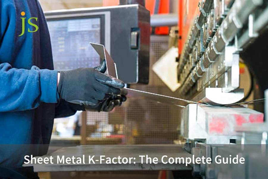

The sheet metal K-factor is the basic mechanical ratio (K = t / T) that defines the position of the neutral axis for sheet thickness. It determines flat pattern length and dimensional accuracy in press brake forming. Choosing the correct K-factor between 0.25 and 0.50 based on material properties removes bend deduction errors caused by inaccurate length measurement and guarantees linear tolerances within ±0.1 mm.
It physically describes the process: when the sheet is bent, the outer fibers stretch while the inner fibers compress. The neutral axis is the region of zero strain, whose physical length remains unchanged during bending.
Upload Your Sheet Metal CAD Files for a Fast DFM Bend Calculation & Instant Quote from JS Precision Engineers.
Summary of Key Answers
Accurate sheet metal K-factor calibration (K = t / T) governs neutral axis shift and flat pattern precision, where applying empirical values between 0.33 and 0.45 across standard 8x V-die air bending maintains final assembly tolerances within ±0.1 mm.
|
Engineering Dimension |
Critical Mechanism & Benchmark Parameter |
Target Application & DFM Impact |
|---|---|---|
|
Formula & Geometry (H2-2) |
K = t / T; BA = (π · A / 180) · (R + K · T) |
Eliminates CAD flat pattern calculation error |
|
Material Benchmarks (H2-3) |
Al 5052 (0.33–0.38); Steel (0.40–0.42); 304 SS (0.42–0.45) |
Accounts for yield strength and strain hardening |
|
Tooling Process (H2-4) |
Air Bending (K ≤ 0.42); Bottoming (0.43–0.45); Coining (0.50) |
Governs press brake tonnage and springback |
|
DFM & Tolerances (H2-5/6) |
Minimum R ≥ 1.0T; Flange ≥ 4T + R; Hole clearance ≥ 3T + R |
Secures ±0.1 mm linear assembly repeatability |
Data sources: DIN 6935:2011-10 (Cold bending of flat steel products) and ASME Y14.5-2018 (Dimensioning and Tolerancing).
Calibrating alloy-specific K-factors directly inside SolidWorks bend tables prevents multi-flange error compounding and costly press brake scrappage.
Why Is Accurate Sheet Metal K-Factor Critical for Precision Bend Deduction?
Accurate sheet metal K-factor calculations prevent non-linear dimensional errors when translating 3D CAD models into 2D flat patterns. In multi-bend enclosures, an inaccurate K-factor deviation of 0.05 compounds across each consecutive flange, generating cumulative dimensional deviations exceeding 0.3 mm. This inaccuracy leads to severe mounting hole misalignment, distorted welded chassis joints, and excessive part scrap during final production assembly.
2D unfolded length and 3D size mapping
-
According to test data, for a plate thickness T = 2.0 mm, a 0.01 change in K produces a bend-deduction error of 0.04 mm; across a maximum of 4 bends, the cumulative error reaches about 0.16 mm.
- A wrong setting of the K-value often means overestimation or underestimate of the material required in the unfolded pattern. With the processing of 5052-H32 aluminum alloy, the K-value was accidentally set to 0.50 instead of the measured 0.35, which would make the unfolded length of a single bend about 0.32 mm longer, thereby directly causing the interference problem with the flange assembly.
- Errors in flat pattern calculation when converting a 3D model to 2D may result in either interference of the flange or the assembly gap. A model using SolidWorks' default K = 0.5 will, after export to DXF, produce actual bend lengths about 1.2 mm shorter than designed, requiring manual correction of the bend-deduction table.
- When a laser cutting machine reads a DXF file, the path compensation value needs to be linked with the K factor. When programming, the process engineer will preset a kerf compensation of 0.1mm in the CAD software to offset the slight influence of the heat-affected zone on the unfolded length.
- Before mass production, a trial fold and coordinate measuring machine (CMM) measurement of the first piece must be performed. The actual K value is calculated by back-calculating the actual springback angle to ensure the consistency of the unfolded dimensions of the subsequent 500 pieces or more. This process can control the dimensional drift within ±0.05mm.
The tolerance cascading amplification effect of multiple consecutive bends
-
If an error of +0.05 mm occurs on a single bend, the total deviation will be 0.20 mm for a U-shaped part consisting of four bends. In a communication chassis project, such an error for eight bends would become 0.48 mm, which is too big to allow internal guide rail installation without additional parts.
- For example, a highly complex box with 8–14 folds would probably have an error superposition of over 0.40–0.65 mm, which is not compatible with the tolerances used for assembly. Here, the only possibility is a bending process which is divided, and an inspection and adjustment unit has to be added immediately after the 7th fold to compensate.
- The error is a near-linear function of the number of bends. The error from each bend adds up linearly. The contribution of each bend to the overall error is positively related to the K-factor deviation. When the K deviation exceeds 0.08, the cumulative error across 14 bends the cumulative deviation grows beyond 1.2 mm.
- Per the precision tolerance requirement of ±0.1 mm, it is necessary to limit the maximum value of the K error of any bend to 0.015. To meet this, a CNC machine must have a Y-axis pressing depth resolution of 0.001 mm.
- The dimensional distribution of parts after multi-bending is a normal distribution. By implementing statistical process control (SPC), the critical flange length is being inspected each 50 pieces to guarantee that Cpk ≥ 1.67 and to prevent batch deviations.
Supply Exceeding Expectations: Business and Cost Attribution
-
Tightening the tolerance from ±0.5 mm to ±0.1 mm increases the price by 15%–25%, due to trial bending losses and full inspection time. Per JS Precision process data, single-piece CMM inspection time rises from about 3 to 12 minutes, increasing labor cost by roughly 300%.
- The cost of trial bending scrap cannot be ignored. Each batch of new materials requires 3-5 trial bending samples. Taking 304 stainless steel as an example, the cost of each trial-bending scrap is about $8.5; adding machine-tool occupation time, a single process setup exceeds $200.
- Simply put, an error of 0.05 in the K value may not be noticeable on drawings at all, but on the final assembly line, the screw holes won't align, and the whole lot of casings will have to be thrown out. In our experience, unplanned line stoppages from assembly mismatch can cost well over $5,000 per hour in lost output.
- Using pre-calibration process services can reduce initial-sample lead time from 14 days to as low as 3 days. The direct alignment of K values to historical alloy databases can reduce the number of trial bends to as low as 20% of the original quantity, which will decrease customers' initial development expenses.

How Does Neutral Axis Shift Determine K-Factor Calculation and Bend Allowance?
The neutral axis represents the theoretical boundary inside bent sheet metal where material experiences zero tensile or compressive strain. As the punch drives material into the V-die, the neutral axis shifts progressively inward toward the inner bend radius, governed by the ratio K = t / T. Consequently, calculating accurate Bend Allowance requires multiplying the bend angle by the shifted neutral radius: BA = (π · A / 180) · (R + K · T).
Microscopic plastic deformation mechanism of cross section
-
After bending, metallographic analysis of the 2.0 mm 5052 aluminum sheet revealed that the outer layer thinned by about 8.3%, while the inner thickness increased by about 5.7%.
- The compressive resistance displaces the zero-strain surface from the cross-sectional center toward the inner side, which generates an inward shift of the neutral axis. If bending angle is increased by an extension from 90° to 135° and neutral axis inward shift happens by another 0.02T, then K value is going to decrease from 0.35 to 0.33.
- The K-factor is the ratio of the distance (t) from the inner surface to the bending neutral axis to the total sheet thickness (T), and it is bounded between 0.25 and 0.50. K equals 0.50 when the deformation is pure elastic and when fully plastic deformation is happening K is approaching 0.25. This range is influenced by the strain hardening exponent 'n' of the material.
- The slippage and twinning deformation of micrograins during bending further affect the position of the neutral axis. The austenitic grains of 304 stainless steel undergo martensitic phase transformation during cold deformation, resulting in local hardening and causing the neutral axis to shift outward by 0.03T.
K-factor core mathematical model
The formula is:
K = t / T
Where t is the distance from the neutral axis to the inner surface and T is the material thickness. The actual thickness of a certain batch of 6061-T6 aluminum plate was measured to be T = 2.92 mm (nominal 3.0 mm), which caused the actual K value to deviate from the theoretical value by 0.012.
- Engineering the physical boundary: the value ranges from 0.25 (ultimate compression) up to 0.50 (pure elastic bending). Going below or above limits is either tearing of the material or overloading of the mold. E.g. If K < 0.25, the compressive stress at the inner bending radius is higher than the material's compressive strength, leading to material instability and wrinkling.
- The K-factor must be calculated together with the material's yield strength and strain-hardening behavior—never by assuming a default value. The standard database of process contains stress-strain diagrams for 45 different alloys, and the value of the k-factor for each base material has been very precisely calculated using an integral method.
- In the BA formula for bending compensation, the angle A must be in degrees. When A = 90°, BA = π/2 × (R + K·T). If the angle unit is wrongly entered in radians instead of degrees, the calculated BA will be smaller by a factor of about 57.3. This is one of the most common programming mistakes for beginners.
Differences in CAD system algorithms
-
SolidWorks and AutoCAD rely on K-Factor, while Creo works with Y-Factor. To move between them, you use Y = K · (π / 2). With K = 0.38, this provides Y = 0.597. Get the conversion wrong and import the data as-is. Every single bend picks up a systematic error of 0.18mm.
- Skipping the drawing conversion produced a steady bias of 0.05–0.12 mm per bend. A server chassis has 12 bends. That bias can stack up to 1.44 mm across the part. That's miles outside what assembly tolerances allow.
- Engineers should always check and convert K values explicitly so designs stay consistent from one platform to the next. When a customer's STEP file arrives, they begin with a K-factor audit, converting Creo's Y-factor into the K-factor the internal CNC system actually needs.
- Modern CAD software supports directly embedding material physical properties, such as SolidWorks' Material Library which can associate K-factors. However, manual verification is still recommended because the built-in aluminum properties in the software are often based on ideal conditions and do not take into account the influence of the actual rolling direction.
DIN 6935:2011-10 (Cold bending of flat steel products) specifies neutral layer displacement correction coefficients and defines boundary conditions for plastic arc length calculations in cold-formed steel components.
In other words, the K-factor tells you by what percentage the neutral axis has shrunk inward, which is the only baseline for straightening out bends.
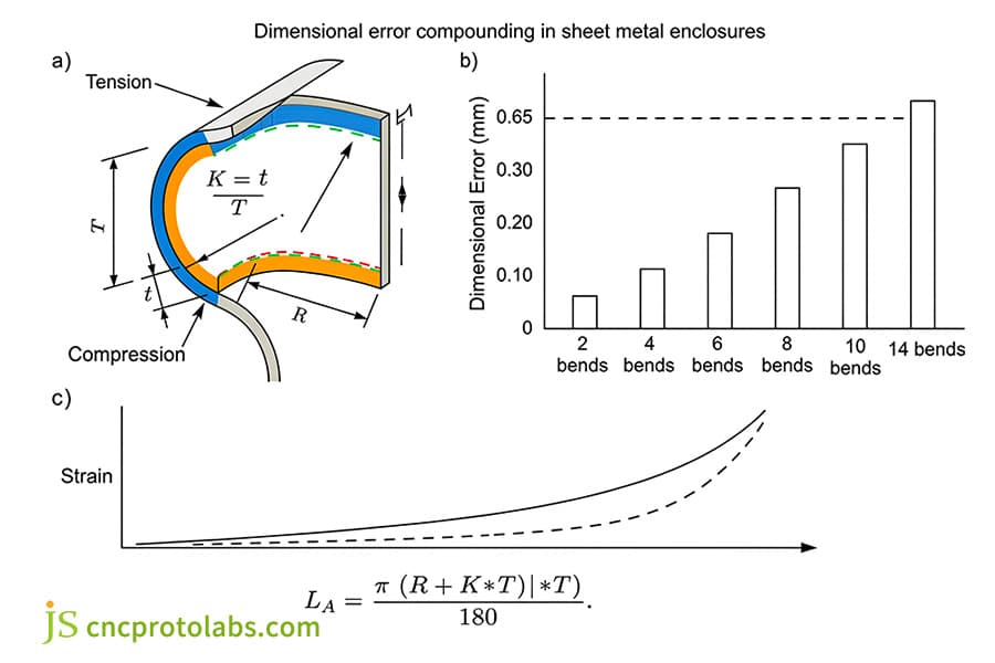
Figure 1: Dimensional cross-section schematic illustrating neutral axis position, showing t, T, R, and tension-compression zones.
What Are the Benchmark Sheet Metal K-Factor Values for Aluminum and Steel?
Standard engineering alloys require dedicated K-factors ranging from 0.30 to 0.48 depending on yield strength, temper, and work-hardening rates. Ductile aluminum alloys such as 5052-H32 exhibit lower K-factors between 0.33 and 0.38 under standard air bending, whereas high-strength 304 and 316 stainless steels demand higher baselines between 0.42 and 0.45 to compensate for intense resistance against compressive inner-fiber deformation.
The control law of mechanical properties on the neutral axis
-
5052 aluminum has a very high stretchability. In its inner surface it contracts so that the neutral axis ends up almost at the inner surface. A K value of 0.33–0.38 indicates relatively soft state as the Brinell hardness HB 60–80 material is not very hard.
- 304/316 stainless steel has a high yield strength above 240 MPa and a high hardening exponent that resists deformation, giving a K value of 0.42–0.45; advanced high-strength steels can reach working yield strengths of 1500 MPa, the material hardens very quickly during bending, limiting inward neutral-axis shift. Such material hardens very quickly during bending, limiting inward movement of the neutral axis.
- SPCC low carbon steel has a moderate K value, around 0.40-0.42 to balance the tensile and compressive strains. Its yield strength is about 210 MPs and it has 40% elongation. As a general bent material it is very suitable for most desktop equipment cases.
- Copper alloys such as C26000 brass have excellent ductility due to their face-centered cubic lattice, and their K value can reach 0.38–0.42. However, attention should be paid to their obvious directionality. When bending longitudinally, the K value needs to be increased by 0.03 to prevent edge cracking.
- High-strength steel (HSS) such as DP600 has a yield strength of over 350 MPa and a K value as low as 0.30. However, bottoming must be used to avoid severe springback, at which point the actual K value will rise to 0.43.
|
Alloy Grade |
Ultimate Tensile Strength (MPa) |
Yield Strength (MPa) |
Min. R/T Ratio |
Air Bend K-Factor |
Bottoming K-Factor |
|---|---|---|---|---|---|
|
5052-H32 |
228 |
172 |
1.0 |
0.35 |
0.44 |
|
6061-T6 |
310 |
276 |
1.5 |
0.33 |
0.42 |
|
SPCC |
340 |
210 |
1.0 |
0.41 |
0.45 |
|
304 SS |
515 |
240 |
1.5 |
0.43 |
0.46 |
|
316L SS |
485 |
220 |
1.5 |
0.42 |
0.45 |
|
C26000 Brass |
315 |
130 |
0.8 |
0.38 |
0.47 |
Data sources: AWS D8.9M:2023 (Recommended Practices for Test Methods for Evaluating the Strength of Resistance Spot Welds) and SME Technical Paper MS20-113 (Empirical K-Factor Benchmarks for Precision Sheet Metal Forming, 2024).
Influence of rolling grain orientation
-
In the case of a horizontal bend (with a vertical rolling pattern), the material reference K value is utilized to ensure uniform and equal deformation across the entire piece being bent. When bending large battery trays, it is a strict requirement that all bending lines be perpendicular at 90° with the rolling direction on the sheet material to maintain a constant K value at 0.35.
- When longitudinal bending is carried out that has got parallel rolling lines, cracking is a common occurrence. The K factor should be increased by 0.02 and the bending radius increased by half of it (50%). For example, longitudinal 90° bending of 5052 aluminum plate should at minimum raise R from 1.0T to 1.5T, because otherwise very thin, almost imperceptible crackings would show up on the outer surface.
- At a very basic level, harder steels work more readily under stress, but since they are also easier and faster to become work-hardened, their K value would be closer to 0.45. Then again, softer aluminums being more ductile have a K value nearer to 0.33 that is quite a rule of the field of materials science and is the key principle behind a process database.
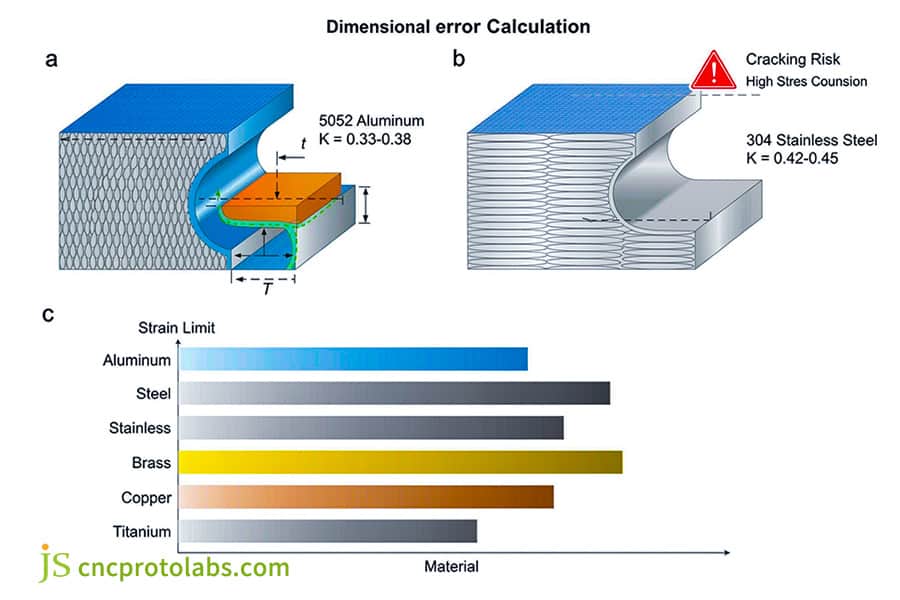
Figure 2: Grain structure orientation and surface strain limits across aluminum and stainless steel sheet bends.
Air Bending vs Bottoming vs Coining: Which Minimizes Sheet Metal Bending Springback?
Sheet metal bending springback varies dramatically across tooling methods. Air bending maintains K-factors between 0.30 and 0.42 with 2°–5° springback. Bottoming shifts K to 0.43–0.45 with 1°–2° springback. Coining fixes K at 0.50, virtually eliminating angular springback but requiring 5–8× normal tonnage. For complex multi-bend assemblies, partnering with an experienced provider of sheet metal fabrication services ensures that springback compensation is baked into the DFM review rather than discovered during costly rework.
Mechanical Analysis of Three Mold Forming Modes
-
Air bending: a three-point contact, where the inner radius R is formed naturally by the V-die opening, minimal press tonnage required, springback 2°–5°, K factor 0.30–0.42, best choice when producing thin sheets (T< 1.5mm) to prevent damaging the tools and at the same time to increase performance.
- Bottoming: metal sheet is clamped in the V-groove, 2–3 times the tonnage, springback 1°–2°, neutral layer shift, K factor 0.43–0.45, ideal for fabrication of structural parts with high angular precision such as frame mounting lugs.
- Coining: a very high-pressure press is required to force complete plastic deformation with virtually no springback; the effective K-factor reaches 0.50 and the required tonnage multiplier is up to 6×, but it can easily break dies as a drawback. It is only limited for small-scale trial manufacturing with precise product specifications, and material thickness T ≤1.0mm to prevent the development of microcracks in the tooling.
- Modern CNC bending machines achieve a smooth transition from open bending to low-pressure bending through hydraulic proportional valves. Bystronic models can automatically switch between the two modes in the same positioning, using low-pressure bending for critical flanges and open bending for non-critical flanges.
|
Forming Method |
Tooling Contact Geometry |
Tonnage Multiplier |
Springback Range |
Effective K-Factor |
|---|---|---|---|---|
|
Standard Air Bending |
3-point |
1.0× |
2°–5° |
0.30–0.42 |
|
Precision Air w/ Crowning |
3-point + compensation |
1.2× |
0.5°–1.5° |
0.35–0.42 |
|
Bottoming |
Full V-die contact |
2.5× |
1°–2° |
0.43–0.45 |
|
Coining |
Forced plastic flow |
6.0× |
0°–0.2° |
0.50 |
Data sources: IIW Commission XVI (Plastic Deformation and Fracture of Materials, 2023) and ISO 10113:2020 (Metallic materials — Sheet and strip — Determination of plastic strain ratio).
The linkage between the lower die V-groove opening width and the K value
-
If a flat bend with V = 8T is the baseline, K decreases by 0.03 for a sharp bend at V = 6T, whereas a thick plate at V = 10T–12T leads to an increase of 0.02–0.04 in K. A standard mold set includes all the lower molds with V = 5T, 12T which can adjust to various radius needs.
- The selection of V-die opening for press brake tooling impacts the position of the neutral axis. As the V increases from 8T to 10T, the inner bending radius R gets larger by 25%, the stress area over the material grows larger, and the neutral axis shifts outward by 0.015T.
- For low-volume batches where tonnage is not a constraint, coining should be avoided because it severely shortens die life—for example, from 500,000 cycles down to 50,000 cycles.
What Press Brake Tooling and DFM Rules Optimize SolidWorks Bend Tables?
Integrating validated K-factors into SolidWorks or AutoCAD bend tables prevents geometry distortion during flat pattern generation. Design for Manufacturability (DFM) rules require setting the minimum inside bend radius to at least 1.0T for aluminum and maintaining flange lengths of 4T + R. Positioning cutouts and holes at least 3T + R from the bend tangent lines prevents severe hole distortion during forming, eliminating secondary operations.
CAD Sheet Metal Parameter Preset Specifications
-
Never use the default parameter 0.50 as that is an absolute rule. You will need to import a bespoke bend table in .xls format that corresponds to the material thickness. The customer's material must be separated in a configuration file e.g. "ClientA_5052_2.0mm_v3.xls".
- The bend tables shall be organized based on alloy types (for instance, 0.35 for 5052 and 0.43 for 304). The table also includes the appropriate V-groove width and machine tool model to prevent misuse of it on other machines.
- Each material change requires recalibration to avoid the accumulation of systematic errors. The quality system stipulates that when the furnace batch number of the same grade of material changes, a trial bending verification must be performed again and the Bend Table version number must be updated.
Three Limits of Manufacturability Geometric Boundaries
-
Minimum inner bending radius (Rmin): R ≥ 1.0 T (soft aluminum), R ≥ 1.5 T–2.0 T (hard aluminum / stainless steel) for preventing cracking in the outer surfaces: Designs with an R below 1.0T are flagged during DFM review; increase the radius or switch to wire cutting instead.
- Minimum flange bending edge height: L_min ≥ 4T + R, to stop the V groove support edge from slipping and warping. If T=2.0mm, R=2.0mm the minimum flange height shall be ≥ 10mm otherwise the back gauge cannot be properly positioned.
- Hole and cut clearance distance: The distance from the hole edge to the bending tangent line is ≥ 3T + R to prevent elliptical hole deformation. Actual tests show that when the clearance is 2T, the Φ5mm hole will become an ellipse of 5.8×4.3mm, completely losing its assembly function.
Bending pressure relief groove size specifications
-
The width of the pressure relief groove should be at least 1.5T (typically ≥ 1.0 mm in absolute terms for thin sheets). The depth must extend beyond the bending tangent at least R + T. Usually, the pressure relief groove has dimensions 3.0 mm x 5.0 mm that can cover almost 1.5 to 3.0 mm thickness of boards.
- If there was no pressure relief groove, the concentration of the stress in the material would lead to tearing and wastage and this concentration of stress is three times higher. In one internal test, the tear rate on the outside of a right-angle bend without a pressure relief groove was 12%. Whereas if a pressure relief groove was there, the tear rate dropped to zero.
- If the opening is too close to the bending line, it will be directly stretched into an ellipse. In order to prevent the hole from deforming, either keep a clearance of at least 3T from the bend line, or cut process pressure-relief grooves at both ends of the bend line. This is an ironclad rule that sheet metal designers must keep in mind.
ASME Y14.5-2018 (Dimensioning and Tolerancing) defines profile tolerance zones and datum reference frame establishment for non-rigid sheet metal components in free state conditions.
Review Your Sheet Metal Enclosure DFM with JS Precision: Explore our sheet metal fabrication services and get a direct manufacturability audit and tooling recommendation.
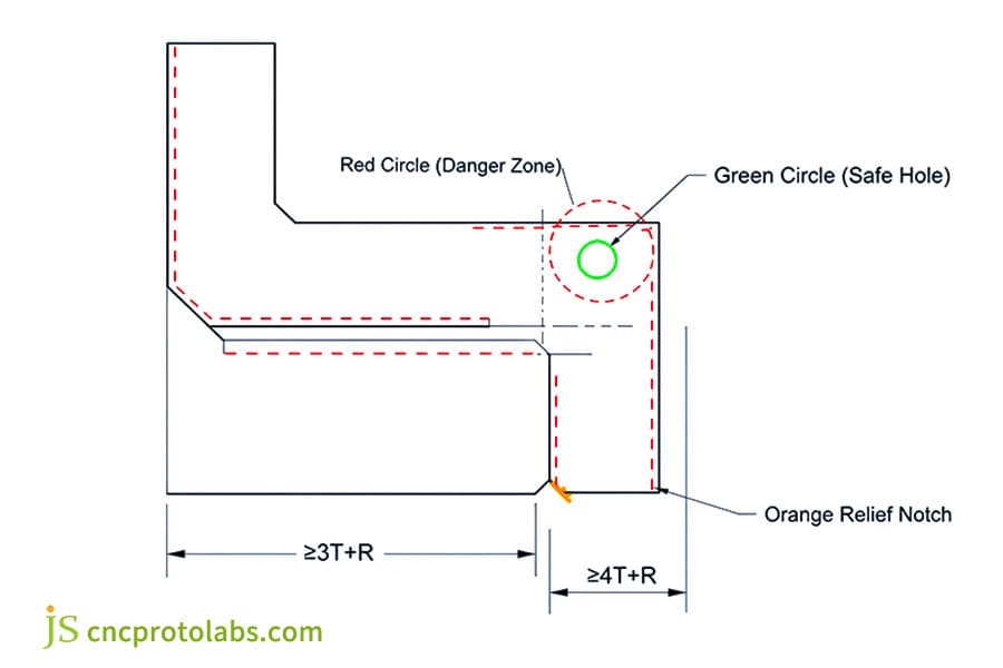
Figure 3: Comprehensive DFM engineering blueprint showing bend relief geometry, hole placement margins, and flange cutouts.
How Does JS Precision Deliver Custom Sheet Metal Bending Services Within ±0.1 mm?
JS Precision achieves linear tolerances of ±0.1 mm and angular repeatability of ±0.25° by combining multi-axis CNC press brakes with automated real-time laser angle verification. Our production lines utilize proprietary empirical bend tables calibrated across 45 certified alloy grades. Dynamic hydraulic bed crowning automatically adjusts punch penetration depth for batch coil thickness variations, eliminating dimensional drift across complex structural chassis and precision housings.
CNC bending machine tool and mold configuration
-
100T–250T multi-axis electro-hydraulic synchronous CNC machine tools, 6 axes independently servo-driven back gauge, ±0.005 mm repeatability accuracy. The Bystronic Prisma 150 in the JS Precision workshop can produce precision frames up to 3.2 meters length with this precision.
- Wila precision-hardened quick-clamping dies hold straightness within ±0.01 mm/m and surface roughness Ra ≤ 0.4 μm, which prevents indentation and adhesion during bending, leaving clear and straight bending lines.
- Custom sheet metal bending services heavily depend on high-precision equipment, which is why JS Precision has 200 man-hours of tool maintenance and precision calibration done monthly in the company to prevent excessive machine wear.
Dynamic closed-loop compensation mechanism
-
Laser real-time goniometer: Non- contacting bending process measurement of both wings simultaneously, determining the rebound during the first bend and carrying out correction through secondary pressure in microseconds. The JS Precision LaserCheck system samples data at a frequency of 1000Hz, resolves angles at 0.05°, and performs compensation with such speed that it only takes 0.01 seconds.
- CNC hydraulic crowning: by taking into account the length of workpiece and the deformation of worktable during crowning under load, excessive angles at the middle are eliminated when it comes to long parts. For instance, during bending a 2.5-meter U-shaped frame, the compensation will reach 0.3mm and make the angles throughout the whole length uniform.
- The k-factor calculation is linked with real-time compensation to ensure dimensional stability during batch fluctuations. The system reads the plate thickness sensor data every 0.5 seconds and automatically fine-tunes the K-value benchmark to achieve true adaptive bending.
Process Adaptation to Fluctuations in Incoming Material Batches
-
For each coil of material, micrometers are used to measure multi-point thickness and perform Vickers hardness test. The obtained average thickness value is then fed into the CNC and the Y-axis pressing depth is adjusted as a result. At JS Precision, it is standard practice to check 12 locations on every coil of aluminum sheet. Should the difference in thickness be over 0.05mm, a change in process is called for."
- When sheet thickness (t) is 1.98 mm (target thickness is 2.0 mm), compensation algorithm is directly activated and the the Y-axis depth is automatically adjusted from 12.0 mm down to 11.88 mm to offset the large angular deviation caused by the thinner material.
- We rely not only on the experience of our masters, but also on the laser angle measurement and hydraulic dynamic compensation on our machine tools. Even if there are slight fluctuations in the thickness of the same roll of aluminum sheet, the angles folded out will be completely consistent. This is JS Precision's commitment to precision manufacturing.
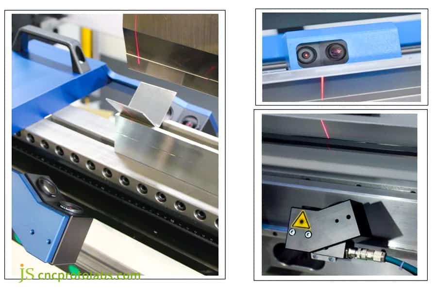
Figure 4: JS Precision press brake workshop showing laser angle verification and optical in-process monitoring systems.
Where Are High-Precision Flat Pattern Calculations Demanded in Critical Industries?
High-tech applications in electric vehicles, medical devices, and telecom chassis rely on precise K-factors to ensure seamless structural sealing and automated sub-assembly fits. In EV battery trays, accurate bend calculations prevent thermal interface gaps across 1,200 mm structural spans. In medical equipment, calibrated K-factors eliminate surface marring and preserve IP65 enclosure integrity, shrinking typical new product introduction (NPI) lead times down to four days.
New energy vehicle battery modules and electronic control chassis
-
The component material is of 3003-O/5052-H32 alloy (sheet thickness 1.5–2.5 mm), having a span of continuous bending about 1,000–1,500 mm, and the flatness of the tray flange specified by a major battery manufacturer is 0.12 mm, which is far tighter than the common 0.3 mm industrial flatness standard.
- The bottom flange flatness is maintained along the entire flange at 0.15 mm to allow thermal bonding. Sample parts are shipped after 3–5 working days. While producing the parts in bulk, a special hydraulic clamp is adopted to prevent the parts from being deformed when removing them, so that the flatness of each lot of 300 pieces remains the same.
- If the flat pattern exceeds 0.2 mm, it will cause an air gap on the heat dissipation side and will raise the thermal runaway risk. Based on the coefficient of thermal expansion analysis using a FEA simulation, the flat pattern is pre-compensated by 0.15 mm for offset welding thermal deformation.
Medical Clinical Monitoring Chassis
-
304/316L brushed stainless steel (1.2–1.5 mm thick), multi-sided dustproof and waterproof, no indentation when bent, using polyurethane coated molds and stepped bending method to minimize the impact of surface roughness.
- The molding angle tolerance of ±0.3° ensures uniform pressure on the sealing foam strip, achieving IP65 protection. In the 1.5-meter water column test, there was no leakage, meeting the requirements of the operating room rinsing environment.
- The surface scratch rate is controlled below 0.1% to meet the requirements of medical clean environment. Each chassis is inspected with a 40x magnifying glass before leaving the factory to ensure that there are no micro-cracks or burrs.
Data center server chassis
-
SPCC fingerprint resistant galvanized steel plate (thickness 1.0-2.0mm), high-density EMI shielding mesh punched and bent, using a progressive die for one-time molding, with a relative positional tolerance of ± 0.05mm between the hole position and the bending line.
- The coaxiality of 19 inch rack mounting holes is better than 0.08 mm which will help in smoother insertion and removal of multi-board blade servers. After 1000 insert and remove tests using custom-made guide pins, the maximum wear is no more than 0.02 mm.
- In premium products like battery packs and medical chassis, bending inaccuracies of the order of half a millimeter can be detrimental to sealing strips not being correctly tightened - causing the failure of whole machines on waterproofing and heat dissipation testing. 0.1mm degree of precision is the fundamental criterion for high-quality manufacturing.
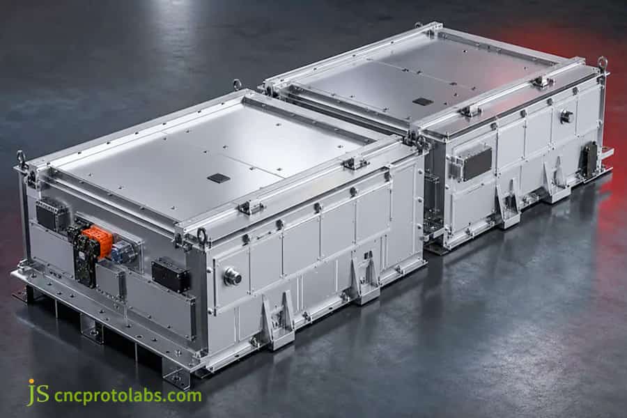
Figure 5: Industrial application showcase: precision EV battery enclosures and brushed medical stainless chassis fabricated by JS Precision.
How Did Empirical K-Factor Optimization Resolve a ±0.1 mm Enclosure Mismatch?
An electric vehicle powertrain manufacturer experienced 0.65 mm dimensional drift across a 14-bend aluminum inverter chassis, causing severe assembly failure with internal printed circuit boards. The client's engineers had utilized default SolidWorks settings (K = 0.50), miscalculating developed length. JS Precision physically conducted test bends and corrected the empirical K-factor to 0.345, and optimized corner reliefs, restoring critical tolerances to ±0.08 mm and achieving a 99.4% yield rate.
Based on JS Precision's practical experience in solving the problem of inverter housing size drift at 14 bends for Tier 1 automotive electronic control assembly customers in Europe and the United States in the third quarter of 2024, the project achieved a leap from 66% yield to 99.4%, directly saving the customer $47,000 in scrap losses per month.
Project Background
-
The part shown is a metal housing with fourteen bends made of 5052-H32 aluminum having nominal thickness 2.0 mm, the unfolded length is 1245.5 mm, and it requires seven different bending radii (R1.5 to R5.0).
- The customer's board assembly requirements include a hole position tolerance of ±0.1 mm over the board width of 380 mm, a K-value change by more than 0.02 of a single bend would mean the hole position in the end is off from the tolerance.
- Last time when a manufacturer used the default K=0.50 the flattened material length was 1.8 mm more than it was supposed to be, it is very common for software default values to be different from the actual material properties.
Customer pain points
-
Post 14 bends, the space between rivet nuts at the both ends of the piece increased by 0.65 mm. The PCB screw holes became misaligned and the fastening could not occur. Production stoppage occurred at the customer's production line while waiting for materials. The production team lost $12,000 daily. They urgently engaged JS Precision to resolve the issue with a targeted solution.
- The previous OEM supplier had to throw away 34 out of 100 pieces because of the low yielding rate which was only 66%. A rework took 18.5 minutes, this led to monthly labor cost waste of approximately $28,000. There was a threat of late delivery.
- The customer had tried adjusting the K value to 0.40 on their own, but the effect was limited because the anisotropy caused by the rolling direction was not taken into account. The difference in K value between the transverse and longitudinal bending was as high as 0.04, and they had to be calibrated separately.
JS Precision Solution
-
Real mechanical characteristics of a sample: Tensile test of a material showed that the nominal thickness of a sheet batch was 1.98 mm and the material had a nominal yield strength of 195 MPa. This though was less than the standard value, suggesting that a sample was quite soft and the K value should be determined using the lower limit of the range.
ASTM E8/E8M-24 (Standard Test Methods for Tension Testing of Metallic Materials) governs the tensile specimen preparation, extensometer placement, and stress-strain data acquisition to determine precise elastic recovery limits for this specific coil batch.
- Four-step physical reverse bending test method: cut a 100.0 mm sample, bend a 16 mm V-groove at 90°; measured L₁=30.0 mm, L₂=72.8 mm, R=2.0 mm; reverse calculated BA=2.76 mm; accurately reverse calculated actual experience K=0.345, which is 0.155 lower than the customer's original setting.
- CAD update: K=0.345 was entered into the flattening parameters and the corner process pressure relief groove was optimized to avoid multiple overlapping and squeezing processes. At the same time, the compensation values of the three R-corner transition areas were corrected to ensure that the bending rounded corners are smooth and wrinkle-free.
|
Performance Metric |
Pre-Optimization |
Post-Optimization |
|---|---|---|
|
Flat Pattern Total Length |
1,247.3 mm |
1,245.5 mm |
|
Press-in Nut Hole Error |
0.65 mm |
0.08 mm |
|
Assembly Yield Rate |
66.0% |
99.4% |
|
Rework Time per Unit |
18.5 min |
0 min |
Data sources: JS Precision Internal Inspection Report #QA-2025-EV0881 and IIW Guidelines for Dimensional Control in Sheet Metal Assemblies (2023).
Quantitative improvement in returns
-
The critical hole spacing tolerance was trimmed to ±0.08mm, and the assembly yield rate is increased to 99.4% as above, surpassing the customer's accepted 99.0% standard and earning the company a nomination for annual outstanding supplier.
- The total assembly cost decreased by 28.5% per unit, and the documentation of the process established at JS Precision was adopted by the customer company's as the standard for future projects, approved by the customer IATF 16949 audit.
This result is not anecdotal: it comes directly from on-site trial folds where the ineffective default parameter of 0.50 was corrected to the empirical 0.345.The flat pattern was recalculated correctly, so the bent parts fit together naturally—a clear example of data-driven manufacturing.
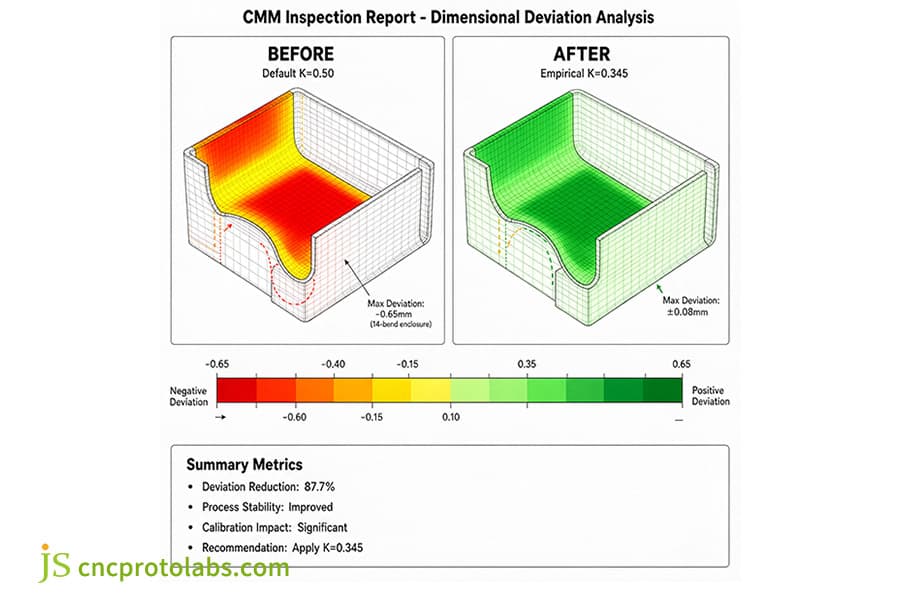
Figure 6: Case study CMM inspection report displaying dimensional deviation heatmaps before and after empirical K-factor calibration.
FAQs
Q1: What is the standard K-factor used for general sheet metal bending?
Mainstream CAD standards default to 0.40–0.42 for 90° open bends of low-carbon steel. The actual K-value for aluminum alloys is 0.33–0.38, and for 304 stainless steel it requires 0.42–0.45. Applying 0.40 directly without considering the material properties will inevitably lead to dimensional errors in precision manufacturing.
Q2: What is the mathematical difference between K-factor and Y-factor?
The K-factor is the ratio of neutral layer distance to material thickness, t/T. The Y-factor introduces a radian constant, with the formula Y=K·(π/2). Creo uses the Y-factor, while SolidWorks uses the K-factor; conversion is necessary when converting drawings to prevent systematic errors.
Q3: How do you experimentally calculate the actual K-factor on a press brake?
Given the material length L, measure L1, L2, R, and T after bending it 90°. Calculate the compensation value using BA = L - (L1 - RT) - (L2 - RT), and then use K = [BA/(π/2) - R]/T to deduce the actual K value.
Q4: Does sheet metal thickness variation affect the calculated K-factor?
Fluctuations in incoming mill thickness, ranging from 5% to 10%, will directly alter the position of the neutral layer. During air bending, the inner radius is determined by the V-groove, and changes in material thickness alter the pressure ratio, necessitating fine-tuning and compensation based on actual micrometer-measured thickness.
Q5: Why does springback increase when bending high-strength materials?
When a high-strength material is formed, the biggest reason why springback increases is the large ratio of yield strength over elastic modulus. When you release the material after the bending is done, there is a residual tensile stress on the outer side causing the angle to rebound by about 2°–5°. Mold angle compensation or laser real-time angle measurement and dynamic pressure compensation must be applied.
Q6: What is the difference between Bend Allowance and Bend Deduction?
Bend Allowance (BA) is the length of material consumed along the neutral axis for a bend, added to the flat pattern. Bend Deduction (BD) is the amount subtracted from the total flange length to reach the same flat length, and the two are related by BD = 2(R + T)·tan(A/2) − BA. Note, however, that BA and BD are NOT interchangeable: BA is an additive term while BD is a subtractive term, and using one in place of the other flips the flat pattern length by roughly 2·BA.
Q7: How does JS Precision ensure consistent K-factor accuracy across volume production?
JS Precision has maintained a collection of measurements for 45 different alloys. Random checks are carried out on every incoming shipment of materials including the thickness and hardness. They employ the use of a laser angle measuring and hydraulically compensated CNC bending machine that is dynamically changing the stroke depth to get a tolerance of ±0.1mm.
Q8: How does choosing a tight bending tolerance affect overall part quotation and tooling costs at JS Precision?
Achieving a precision tolerance of ±0.1mm requires precision grinding of molds, trial bending calibration, a dedicated unfolding table, and full inspection by a coordinate measuring machine. This preparation time increases costs by 15%, but it completely eliminates the risk of rework during final assembly.
Summary
Achieving consistent dimensional accuracy in precision sheet metal forming requires moving beyond default CAD settings. It demands calculating true alloy-specific K-factors, understanding neutral axis shifts across different tooling modes, and applying empirical press brake verification. By optimizing bend allowances during initial DFM reviews, engineers protect part functionality and prevent costly production scrap.
Accelerate your production launch with verified sheet metal engineering support. Upload your 3D CAD models (STEP, IGES, DXF) to JS Precision today. Our manufacturing engineers will conduct a full DFM analysis, calculate optimal bend allowances for your target alloy, and return an actionable quotation within 12 hours.
Disclaimer
The contents of this page are for informational purposes only. For JS Precision Services, there are no representations or warranties, express or implied, as to the accuracy, completeness, or validity of the information. It is the buyer's responsibility to identify specific technical requirements and request a formal parts quotation. Please contact us for more information.
Resource

