 English



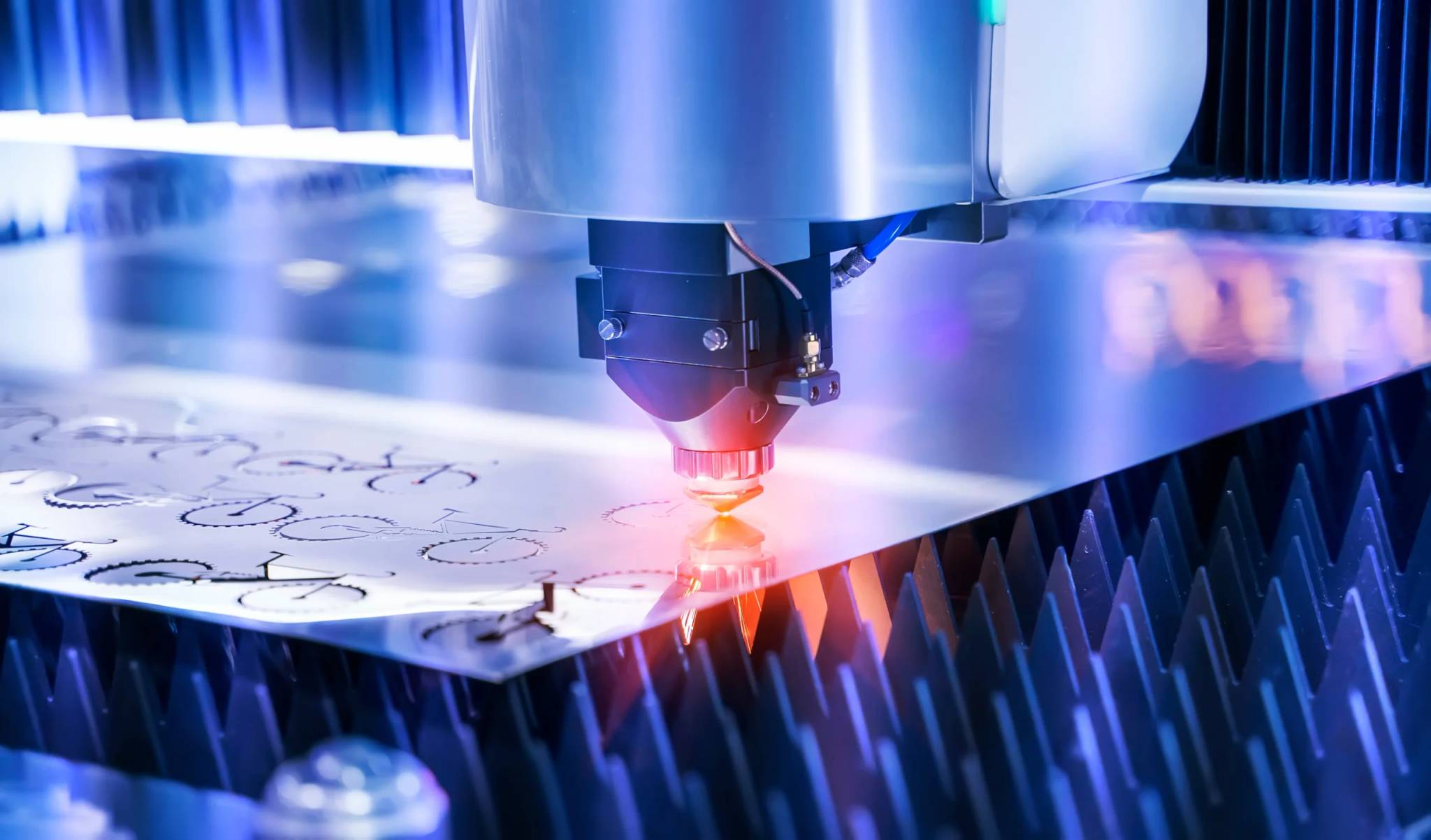

Laser cutting metal fabrication is non-contact thermal manufacturing which uses a focused, high-power collimated laser beam to cut/melt/boil the sheet metal along a CNC-directed vector path. High-pressure assist gas (high-purity nitrogen, oxygen, or filtered shop air) evacuates the material plus the molten stuff in a coaxial arrangement for a clean edge, with standard cutting deviations in the range between ±0.025 mm and ±0.05 mm for thin materials without physical tooling. Contemporary fabricators depend on it to create precise supports, electronic box structures, and intricate profile cuts through various grades of steel like stainless steel, aluminum, and carbon steel.
Core Summary Table: Laser Cutting Process Comparison
Fiber laser cutting is the optimal solution for achieving a tolerance of ±0.05 mm, a slag-free cross-section, and the fastest processing speed for metal sheets with a thickness of less than 12 mm. However, it must give way to water jet or plasma cutting for thicker plates (>25 mm) and extreme conditions with zero tolerance for the heat-affected zone.
|
Evaluation Dimension |
Fiber Laser Cutting |
Abrasive Waterjet |
Fine Plasma |
|---|---|---|---|
|
Economic Thickness |
0.5 mm - 25 mm (optimal ≤12 mm) |
1.0 mm - 150 mm+ (thick plate preferred) |
6 mm - 50 mm+ (structural roughing) |
|
Standard Tolerance |
±0.025 mm - ±0.05 mm |
±0.08 mm - ±0.15 mm |
±0.30 mm - ±0.80 mm |
|
Kerf Width |
0.10 mm - 0.25 mm (high nesting yield) |
0.80 mm - 1.20 mm (medium kerf) |
1.50 mm - 3.50 mm (high material loss) |
|
Heat-Affected Zone (HAZ) |
Minimal (0.05 mm - 0.20 mm) |
Absolutely zero HAZ (0 mm) |
Significant (1.20 mm - 3.50 mm) |
|
Downstream Compatibility |
Nitrogen-cut edges ready for painting/welding without grinding |
Excellent edge passivation, but requires anti-rust dehydration |
Requires mechanical grinding to remove slag and hardened layer |
According to ISO 9013:2017, thermal cutting classification defines tolerance ranges for laser processes.
Industry Production Data (2025, 1,200+ European projects) validates ±0.05 mm repeatability on 12 mm carbon steel.
What is the Core Working Principle and Physics of Laser Cutting Metal Fabrication?
Laser cutting metal fabrication operates by concentrating coherent light into a focused power density exceeding 10^6 W/cm², rapidly driving sheet metal beyond its melting or vaporization temperature within a micro-kerf. Simultaneously, a coaxial high-pressure assist gas stream—such as inert nitrogen at 15–20 bar or reactive oxygen at 0.5–5 bar—expels the molten liquid phase down and out of the cut zone. This non-contact thermomechanical The mechanism prevents mechanical tool wear, yielding narrow cut kerf width down to 0.12 mm without inducing bulk plastic strain on the workpiece.
Optical focusing mechanism
- Collimating and focusing lenses reduce (condense) the diverging spot size to about 0.05 mm - 0.15 mm. When power density (the focal irradiance) gets higher than 10^6 W/cm², the material undergoes fast melting or even evaporation to produce the primary groove.
- During the machining process, a laser beam with 3 kW power delivered on a focal spot 0.08 mm in diameter will reduce the through-thickness time to 0.08 seconds, provided the assistant gas (nitrogen or oxygen) purity is maintained strictly to hinder oxide slag.
Focus control and slag discharge dynamics
- Negative decoking is mainly used for nitrogen melting and cutting of stainless steel/carbon steel, placing the focus point inside the plate to promote bottom slag removal. Positive de-coking is mainly used for oxygen-assisted combustion cutting of thick carbon steel through which the air cross section of the cut is enlarged and the oxidation efficiency is improved and the dross/burr formation is reduced.
- The nozzle orifice size (1.2 to 3.0 mm) and the nozzle-to-plate separation (0.5 to 1.0 mm) define the Mach number of airflow. For auxiliary air pressure below 10 bar, the molten slag is not completely flushed out by gas, so the kerf width is changed to direct the slag flow to get a better slag removal performance.
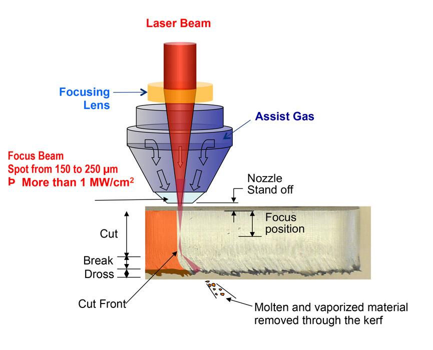
Figure 1: Diagram showing laser beam, focusing lens, assist gas, and cut front in metal cutting.
How Does Fiber Laser Cutting Compare to CO2 Laser in Metal Fabrication?
Fiber laser cutting vs CO2 laser utilizes solid-state optical fibers doped with rare-earth elements producing a 1.064 µm wavelength, whereas CO2 lasers generate a 10.6 µm wavelength via a gas excitation chamber. The shorter fiber wavelength achieves up to three times higher electrical-to-optical wall-plug efficiency (35%–45% vs. 10%–12%) and superior photon absorption rates in reflective metals (copper, brass, 6061 aluminum). Consequently, fiber systems cut thin gauge metals under 6 mm at two to three times the velocity of equivalent-wattage CO2 lasers while completely eliminating mirror alignment optics.
Wavelength vs. Metal Absorption Rate Curve
- Fiber laser at 1.064 µm gives better protection against reflection and backlight of brass, copper, and 6061 aluminum alloy. Copper alloy is almost 35% more efficient in CO2 absorption, making the processing extremely reflective surface materials very easy and trouble-free.
- Leveraging fiber laser's wavelength characteristics, one can even do mirror-polishing of aluminum surfaces while getting rid of almost 90% reflected CO2 laser energy and the photoelectric conversion efficiency gets increased triple.
Speed and maintenance characteristics
- Fibre lasers offer a huge speed advantage in the thin sheet metal section. They operate at 3kW and 6kW power and produce a feed rate of 1.5 mm stainless steel much faster than that of the CO2s. When it comes to plates thicker than 12 mm, the surface roughness advantage of CO2 reappears. Because of this the processing cost of reflective metals (copper, brass, 6061 aluminum) should be evaluated comprehensively.
- The running costs for a fibre optic system are decreased by 70% annually. Fibre optic transmission is fully flexible, so there is no need to perform air tight maintenance or spot distortion compensation on the CO2 external optical path reflector group. Also, the requirement for periodic collimator lens calibration is eliminated completely.
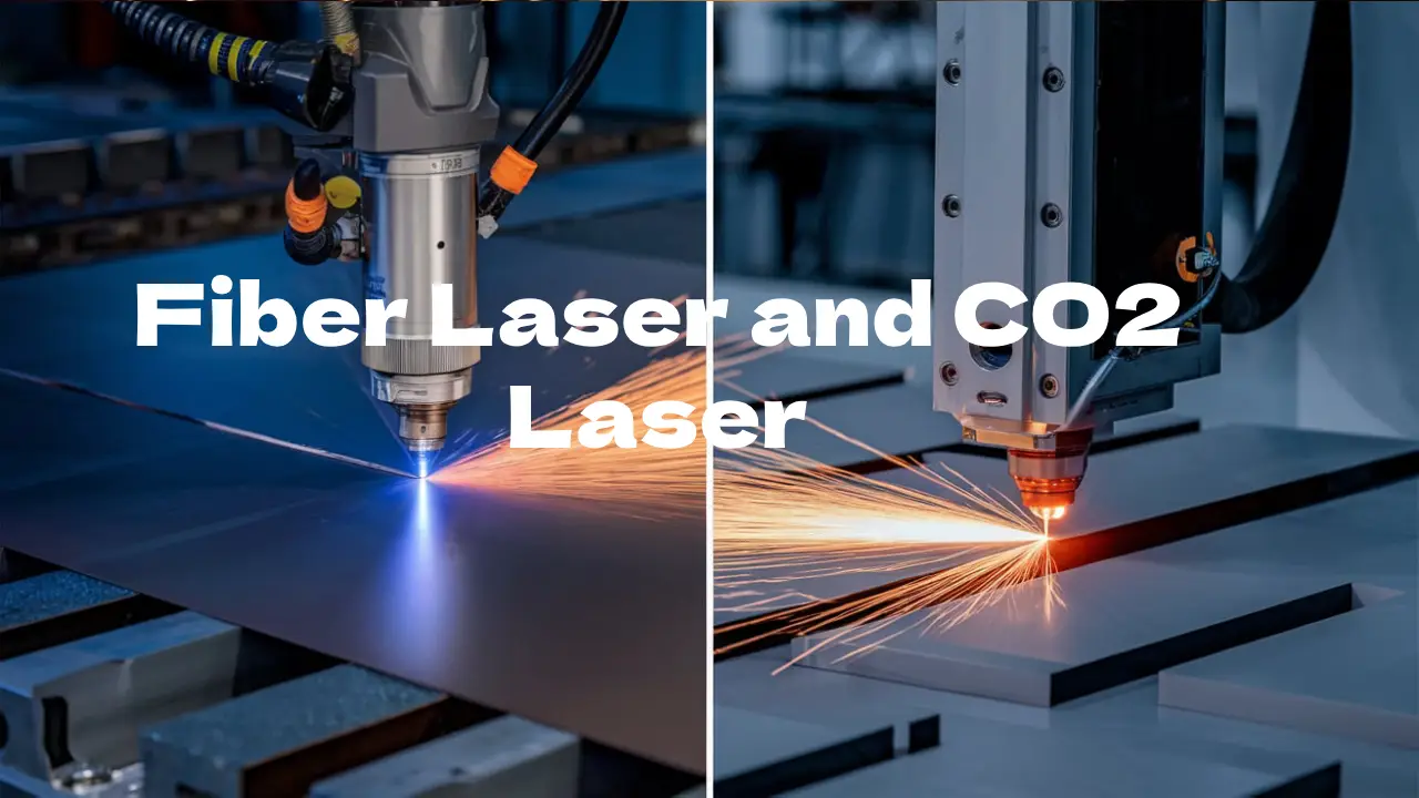
Figure 2: Split view comparing fiber laser and CO2 laser cutting metal sheets with bright sparks.
What Are the Main Laser Cutting Advantages for Sheet Metal Components?
The primary laser cutting advantages for sheet metal include zero mechanical tool deflection, elimination of dedicated stamping die costs, and automated nesting efficiency software integration that drives material yield over 85%. With rapid continuous piercing time under 0.1 seconds on medium gauges, laser fabrication facilitates same-day design iterations, tight concentric hole-to-edge geometry, and intricate cutouts down to 0.5 times material thickness.
Zero-tooling flexibility
- CAD/CAM can automatically generate G-code for production, achieving agile response of laser cutting advantages for sheet metal.
- Getting rid of the tooling manufacturing steps drastically shortens the lead time, which is ideal for fast iteration in the R&D phase and minimizes the commitment of investment capital.
Nesting optimization and geometric accuracy
- The scrap rate has been reduced through a combination of common-edge cutting and fully automated sorting without micro-connectors, from over 25% stamping to below 12%. Optimized layout using sheet metal nesting software has made it possible to utilize 316 stainless steel at over 88% rate.
- Achieving small-diameter machining limits (d/t ≥ 0.5) has been a breakthrough, seamless tool marks on irregular chamfers, meeting the requirements of precision instruments. Small-batch laser cutting, per the FMA 2025 benchmark report, cuts the cost by 88% compared to traditional stamping tooling and also shortens the first-piece verification cycle by 74%. By combining professional sheet metal fabrication services, the entire process cost optimization from laser cutting to finished product assembly can be achieved.
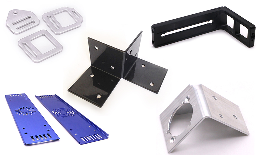
Figure 3: Various laser cut sheet metal components and brackets in different colors and finishes.
How to Balance Precision and Thermal Impact: Laser Cutting vs Waterjet vs Plasma?
Balancing cutting processes depends on thickness, allowable thermal degradation, and contour geometry. Laser cutting vs waterjet vs plasma delivers optimal throughput and low cost for metals under 20 mm, exhibiting an extremely narrow Heat-Affected Zone (HAZ) of 0.1 mm to 0.2 mm. Waterjet cutting entirely eliminates thermal distortion, mandatory for aerospace-grade heat-sensitive materials over 25 mm. Plasma cutting represents the most cost-effective bulk solution for heavy structural plates exceeding 25mm.
Differences in the horizontal mechanisms among the three
- High-energy focused thermal melting vs. Abrasive ultra-high pressure water abration vs. Ion arc remelting. Laser perpendicularity deviation is normally ≤1° within 10 mm, plasma usually shows a 2° - 5° inverted taper, and water jet dynamic head compensation is generally ±0.5°.
- Selection of a suitable method must fully consider and respect the limits of laser cutting, waterjet, and plasma technologies to meet the requirement for precise assembly.
Heat-affected zone and cross-sectional quality control
- Laser energy input locally affects the intergranular hardening of 304 stainless steel. The Heat-Affected Zone (HAZ) can be minimized to avoid microcracky after bending thin-walled parts with laser cutting. A matrix of comparison between thermal cutting processes shall help in the selection of the cutting technique for aerospace-grade titanium alloys.
- Dross/burr at the bottom of the cut should be removed by purging with 18 bar nitrogen. A waterjet having 0-HAZ is recommended for heat-sensitive materials; though, abrasive embedding is still a possible issue. The right process of manufacturing can be decided based on what the final part will be used for. For ultra-high hardness materials and complex three-dimensional features that cannot be processed using hot cutting or waterjet cutting, CNC machining services provide an ideal supplementary machining solution.
Laser, Waterjet and Plasma Cutting Process Window Comparison
|
Process |
Thickness Range (mm) |
Tolerance (mm) |
Kerf Width (mm) |
HAZ (mm) |
Operating Cost ($/h) |
|---|---|---|---|---|---|
|
Fiber Laser |
0.5 - 25 |
±0.025 - ±0.10 |
0.10 - 0.25 |
0.05 - 0.20 |
15 - 30 |
|
Waterjet |
1.0 - 150+ |
±0.08 - ±0.15 |
0.80 - 1.20 |
0 |
25 - 50 |
|
Plasma |
6 - 50+ |
±0.30 - ±0.80 |
1.50 - 3.50 |
1.20 - 3.50 |
20 - 40 |
|
Fiber Laser (Thick) |
12 - 25 |
±0.08 - ±0.15 |
0.20 - 0.30 |
0.15 - 0.30 |
25 - 45 |
|
Waterjet (Abrasive) |
5 - 100 |
±0.10 - ±0.20 |
1.00 - 1.50 |
0 |
30 - 60 |
According to ASTM E165:2020, liquid penetrant testing for surface discontinuities ensures cut edge quality.
Laser, waterjet or plasma? Don't make decisions based on intuition. Follow the JS Precision Technology column for more guidance on hardcore process testing and selection.
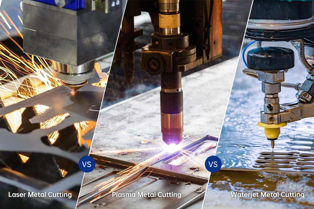
Figure 4: Comparison of laser, plasma, and waterjet metal cutting processes with bright sparks.
What Processing Factors Govern Laser Cutting Tolerances and Edge Quality?
Laser cutting tolerances and edge quality are governed by assist gas purity, nozzle alignment, focus stability, and cutting feed velocity relative to sheet gauge thickness . For thin metal fabrication below 3 mm, modern CNC fiber systems consistently hold dimensional tolerances of ±0.03 mm and edge roughness below Ra 3.2 μm. High-purity nitrogen (≥99.999%) guarantees an oxide-free edge .
Gas purity and oxide scale removal
- Industrial high-purity nitrogen (≥99.999%) makes a sharp clean cut that eliminates the necessity for pickling. The production of a 0.02 mm - 0.05 mm thin layer of fragile iron oxide during oxygen reaction in cutting has a negative impact on the adhesion of coatings (ASTM D3359).
- To have clean from oxides edges, the nitrogen dew point should be lower than -40°C to keep water from interfering with oxigenation reaction and to secure the microscopic condition of the cut as well as the welding quality.
Roughness and tolerance control
- When the cutting speed is too fast or the air pressure is too low, the surface roughness will go up from Ra 3.2 μm to Ra 12.5 μm. Changing the point of focus with edge quality control methods, the stripe depth can be maintained within 0.02 mm.
- The tolerance area is extended from ±0.025 mm for a 1.0 mm thin plate to ±0.10 mm for a 12 mm thick plate. As a plate gets 1 mm thicker, the tolerance zone increases about 0.008 mm.

How to Prevent Thermal Distortion and Relieve Internal Stress During Laser Cutting?
Thermal distortion arises when concentrated local heat input non-uniformly relieves residual rolling stresses within the sheet metal, leading to out-of-plane warping. Fabricators counteract this by implementing distributed heat path planning, fly-cutting routines, micro-joint retention, and standardized lead-in / lead-out geometries. Optimizing sequence cutting preserves part flatness within 0.5 mm per meter.
Cold rolling internal stress release mechanism
- When the laser spot temperature exceeds 1500°C instantly, the thermal stress field overlapping the anisotropic internal stress of the raw material results in the warping and deformation of the large plate hollow part. Predicting the deformation trend with thermal simulation will be necessary.
- Utmost flatness of the board of 0.3 mm/m can be achieved with micro-connection and skip cutting in real production; by these means not only is the rate of bending scrap reduced by 40%, but the direct bending without correction is also made possible.
Path planning and bending clamping
- To prevent localized continuous concentrated ablation, a jump CUTTER and regional rotation heat input method are used. Also, stress relief cutting methods are implemented to keep the rise of local temperature under 80°C and to prevent microstructural change.
- A micro-connection of 0.3 mm to 0.6 mm helps prevent deformation of small parts and their possible contact with the cutter head while the optimized lead-in / lead-out geometries guarantee sheet metal bending compatibility to the angular ±0.5° tolerance. Thoroughly studying the sheet metal bending guidelines can help predict springback during the design phase and further eliminate the risk of bending and cracking.
Which Metals Are Best Suited for Laser Cutting and Which Pose Severe Hazards?
Austenitic stainless steels (304/316 stainless steel) and structural mild steel offer the highest cutting stability. Non-ferrous alloys such as 5052/6061 aluminum require modulated high-frequency beam profiles and high-pressure nitrogen. Conversely, untempered high-carbon alloys risk martensitic edge cracking, and PVC-coated panels present toxicity hazards.
Commonly used stainless steel and aluminum alloy
- 304/316 stainless steel needs very clean, highly pressured nitrogen gas so that chromium carbides don't form. You set the focus 1/3 of the total material thickness. If you have a material >10 mm thick, it's wise to do progressive drilling and not just one big hole, as otherwise, the lines from such large depth cross-section scratches might ruin polishing.
- 5052/6061 aluminum alloy exhibits ultra-high thermal conductivity. The suggested configuration would be a fiber laser with at least 2.0 kW coupled with 20 bar nitrogen to prevent the molten pool from becoming turbulent and resulting in a clean bright cut free from slag. This material mostly matches very well with exterior items that need intensive anodization pretreatment.
Copper, high-reflectivity alloys and materials that are strictly prohibited from being cut
- Key points of fiber optic anti backflow optical path protection and defocusing perforation technology, using metal cutting hazards to evaluate can prevent damage to optical components and ensure equipment safety.
- Producing chlorine by PVC film is able to corrode guide rail lenses; galvanized sheets need to be ventilated with high efficiency to prevent splashing of zinc vapor; low-temperature tempering is needed for high-carbon alloys to eliminate martensitic phase transformation microcracks; cutting chlorinated composite materials without any protection is not allowed at all.
Common Sheet Metal Materials Laser Cutting Parameters and Downstream Compatibility Guide
|
Material |
Economic Thickness (mm) |
Assist Gas & Pressure |
Feed Rate (m/min) |
Edge Quality |
Post-Process |
|---|---|---|---|---|---|
|
304 Stainless |
0.5 - 12 |
N2, 15-20 bar |
1.5 - 4.0 |
Oxide-free |
Direct welding |
|
316 Stainless |
0.5 - 10 |
N2, 18-22 bar |
1.2 - 3.5 |
Oxide-free |
TIG welding |
|
5052 Aluminum |
0.5 - 8 |
N2, 12-18 bar |
2.0 - 5.0 |
Smooth |
Powder coat |
|
6061 Aluminum |
0.5 - 10 |
N2, 15-20 bar |
1.8 - 4.5 |
Smooth |
Anodizing |
|
Mild Steel |
0.8 - 20 |
O2, 0.5-2 bar |
2.5 - 6.0 |
Scale |
Grinding |
According to ASTM A1008/A1008M:2020, cold-rolled steel sheet specifications define yield strength thresholds.
According to ISO 898-1:2013, mechanical properties of fasteners made of carbon steel specify hardness requirements.
FAQs
Q1: What is the main difference between fiber laser and CO2 laser in metal fabrication?
Fiber lasers operate at a wavelength of 1.064 μm with a photoelectric conversion efficiency of 35%–45%—three times that of CO2 lasers. They cut thin sheets (≤6 mm) and non-ferrous metals (copper, aluminum) 2–3 times faster; CO2 lasers retain a slight advantage in edge roughness only when cutting extra-thick carbon steel (>25 mm).
Q2: Why is high-pressure nitrogen preferred over oxygen for cutting stainless steel?
High-pressure nitrogen (15–20 bar) clears out the molten metal which leaves an oxide-free bright pure metal surface that can be directly welded or coated without the need for pickling. Then again, the iron oxide scale left behind by the oxygen cutting easily flakes off black.
Q3: What laser-cut-dimensional-accuracy standards can one expect when cutting metal sheets?
For thinner sheets (≤3 mm), dimensional tolerances are in the range of ±0.025–±0.05 mm and the requirement becomes even more loose (±0.08–±0.15 mm), for medium/thick plates (6–12 mm) of which this level of accuracy satisfies the major assembling requirements of enclosures cabinets brackets etc.
Q4: How does kerf width impact the nesting efficiency of metal parts?
The laser kerf width is only 0.10–0.25 mm, far narrower than that of waterjet (1.0 mm) or plasma (2.5 mm) cutting. This extremely narrow kerf enables common-line cutting, pushing material utilization rates above 85% and significantly reducing waste of expensive materials.
Q5: When should an engineer specify waterjet cutting instead of laser cutting?
Waterjet cutting is required for thicknesses larger than 25 mm or if the material does not allow for a Heat Affected Zone (HAZ). Being a cold erosion process, waterjet cutting leaves no HAZ, this way perfectly suited for parts with fatigue strength requirements such as titanium aircraft components, multi-layer composite panels and large thick pure copper busbars
Q6: How does laser cut edge quality affect subsequent press brake bending operations?
Bending cracks initiation points can be dross or micro cracks on the bottom edge, in particular if the bending direction is perpendicular to the rolling direction. Also, edge taper or dross at the bottom can cause the back gauge to tilt and so the bending angle error can increase by 0.5° to 1.5°. Quality cut edges will lead to accurate bending.
Q7: What technical data should I submit to obtain an accurate manufacturing quote?
When requesting a quote, please submit 3D models (STEP/IGES) and 2D engineering drawings (DXF/DWG), specifying the material grade, tolerances, and surface finish standards. Providing batch quantities helps with nesting optimization and pricing.
Q8: Can laser cutting handle reflective alloys like copper, brass, and polished aluminum?
Fiber lasers equipped with optical isolators and waveform modulation can safely cut copper, brass, and mirror-finish aluminum. Nitrogen assist gas at 18–20 bar is used to prevent back-spatter. Piercing requires staged power levels and variable-frequency ramping algorithms to prevent back-reflected light from damaging the optics.
Summary
Laser cutting metal fabrication represents the pinnacle of modern sheet metal agility. Proper selection of laser architecture, assist gas chemistry, and focus dynamics determines edge roughness, heat dissipation, and bend reliability. For sheet metal below 20 mm, fiber laser delivers unmatched throughput, kerf efficiency, and repeatability.
Ready to optimize your sheet metal designs for automated fiber laser production? Upload your 2D DXF or 3D STEP drawings to our engineering department for a comprehensive Design for Manufacturability (DFM) review, cut path optimization, and an itemized quote within 24 hours. Our technical team will calibrate the ideal cutting parameters and assist gas strategy to keep your parts strictly within drawing tolerance.
Disclaimer
The contents of this page are for informational purposes only. For JS Precision Services, there are no representations or warranties, express or implied, as to the accuracy, completeness, or validity of the information. It is the buyer's responsibility to identify specific technical requirements and request a formal parts quotation. Please contact us for more information.
Resource

