 English



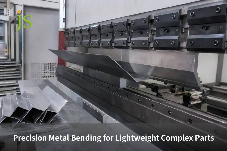

Precision metal bending shapes lightweight alloys into micron-accurate complex parts with angular tolerances of ±0.1° and linearity deviations of ±0.05 mm. Using multi-axis closed-loop servo press brakes, anisotropic material compensation, and mark-free tooling, JS Precision delivers these results consistently across 6061-T6, 5052-H32, Ti-6Al-4V, and thin-wall stainless steel.
Quick Answer: Precision Metal Bending vs Conventional Sheet Metal Bending
|
Process Parameter / Metric |
Conventional Sheet Metal Bending |
JS Precision Precision Metal Forming Services |
Engineering & Assembly Benefit |
|---|---|---|---|
|
Angle Tolerance |
±0.5° – ±1.0° (offline sampling) |
±0.1° – ±0.2° (real-time dynamic laser angle compensation) |
Eliminates cumulative multi-bend interference; raises first-pass assembly yield |
|
Linear Dimensional Tolerance |
±0.20 mm |
±0.05 mm (high-rigidity 8-axis CNC servo backgauge) |
Meets tight assembly gaps of precision electronics & medical structures |
|
Lightweight Material Forming |
6061-T6 / titanium prone to cracking & high springback |
Grain-orientation control + adaptive material K-Factor database |
Enables direct substitution of high-strength light alloys for complex castings |
|
Cosmetic Surface Quality |
V-groove press marks & scratches common |
Polyurethane lower-die pad + roll-a-v die (mark-free bending) |
Preserves Ra ≤ 0.4 μm scratch-free surface before anodizing or plating |
Key result: combining a multi-axis closed-loop servo press brake, material-anisotropy compensation, and specially designed mark-free tooling delivers high-precision bending that cuts the trial-run scrap rate for lightweight complex parts from 8.2% to below 0.5% (JS Precision internal production data, 2024).
According to ISO 2768-1:1989, general tolerances for linear and angular dimensions directly affect the feasibility of achieving tight bending tolerances; JS Precision integrates these limits into every cost estimate.
Why Do Lightweight Metals Exhibit High Springback and Cracking in Precision Metal Bending?
Precision metal bending must compensate for the high yield-strength-to-elastic-modulus ratio of lightweight alloys, where uneven stress release between the inner and outer bend surfaces drives angular springback and intergranular tearing.
Mechanical response and grain orientation mechanism
- 6061-T6, 5052-H32 and Ti-6Al-4V in the plastic deformation zones of lightweight metal bending are mainly influenced by yield strength, the work hardening capability (n value), and grain rolling direction.
- The bending of the parallel rolling direction results in the critical extension exceeding that of the vertical direction and the variations in springback can be up to 30%-45%. As a result, K-Factor has to be assigned separately based on the crystallographic orientation in the unfolding calculation.
- The minimum cold bending radii for R/t of a precipitation-hardening 6061-T6 alloy should be at least 3, otherwise the shear stress developed at the outside grain boundary will exceed the fracture strength and intergranular tearing will take place.
Springback Compensation Calculation Path
- The springback compensation angle Δα is determined by the material's elastic modulus E, yield strength σ_y, and bending inner radius R. For a typical 6061-T6 (R/t=3), the average springback compensation angle is approximately 2.5°–3.5°.
- To make a dynamic K-Factor database, JS Precision uses the measured plate thickness and batch hardness to determine how much the neutral layer has shifted. They adjust the material batches, so from the source onwards, springback does not build up.
According to ISO 7438:2020 (Metallic materials — Bend test), minimum bend radii for age-hardened aluminum are governed by yield strength and elastic modulus; JS Precision applies these relationships in its K-Factor compensation model.
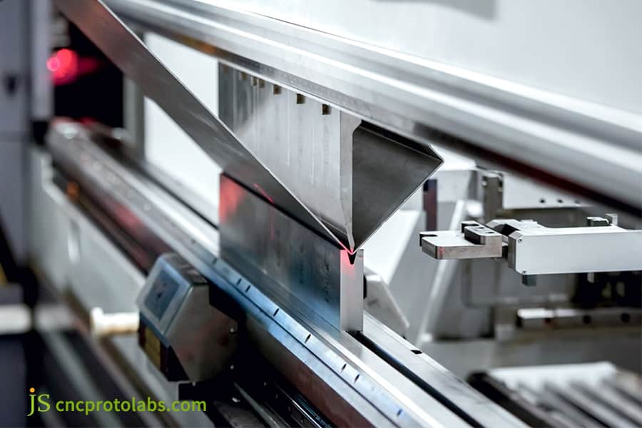
Figure 1: Press brake bending lightweight metal with laser.
How Does CNC Metal Bending Service Ensure Tight Tolerances for Complex Thin-Wall Parts?
Metal bending achieves a cumulative tolerance of ±0.05 mm on complex thin-wall parts through an 8-axis servo drive, real-time mechanical crowning compensation, and closed-loop dynamic laser angle correction.
Multi-pass error superposition and deformation prevention control
- Thin-walled parts with material thicknesses of (0.5–2.0 mm) may deviate from a single-pass angular change of ±0.15° to a linear deviation after 5 consecutive CNC precision bending operations of over 0.20 mm. So, pass-by-pass dynamic compensation has to be utilized.
- Air bending sets the angle by the depth of bottom dead center, the pressure is mainly on the inside, which makes it good for forming of flexible large angles; in bottom bending, the mold is force-fitted to a shape, so angle reproducibility is much higher, with Cpk ≥ 1.33.
- In addition, by changing depth of bottom dead centre every 0.01 second, the 8-axis CNC electro-hydraulic servo system will constantly, in a dynamic way, compensate angle drift which comes from material batch thickness tolerance of ±0.02 mm. On top of that, using such system, the locking of accumulated errors from multiple complex parts bending shall be within 0.05 mm.
8-axis linkage calibration and dynamic angle measurement process
- The optical laser goniometer gathers the exact bending angle at the instant of the bending, returns it for the feeding to the CNC controller, and then it matches the target angle.
- Servo-guided calibration automatically corrects the positioning co-ordinates based on the actual measured plate thickness so it is able to eliminate positioning errors that thickness tolerance could have caused.
- The system enters the compensation value into the current process parameters, and the angle standard deviation remains stable within ±0.08° for more than 200 consecutive production runs.
Send your 3D CAD drawings to JS Precision to get a free DFM assessment and thin-walled part bending tolerance analysis report.
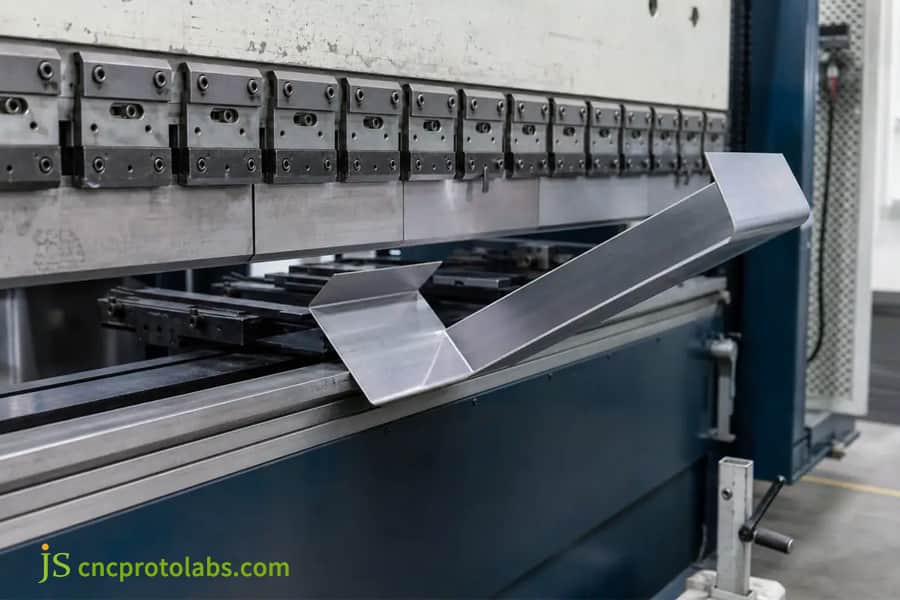
Figure 2: CNC press brake bending complex thin wall part.
How Does Precision Metal Forming Eliminate Die Marks on Cosmetic Lightweight Parts?
Precision metal forming eliminates die marks on cosmetic lightweight parts by replacing hard V-die contact with polyurethane cushion pads, Roll-a-V mark-free lower dies, and polymer protective films that prevent direct metal-on-metal friction.
Contact stress concentration and indentation formation
- Conventional cemented carbide V-shaped lower dies result in stress concentration on the surface of the aluminum plate, which is easy to cause obvious extrusion marks and scratches before anodizing.
- The Roller-type Non-marking Lower Die (Roll-a-V) converts sliding friction into rolling contact, makes the shear stress distribution more even, and completely removes linear indentations.
- The polyurethane elastic gasket takes in local contact stress peaks, cutting down the surface scratch rate from 14.5% to 0% on both 5052 and 6061 aluminum plates, without compromising the structural integrity. (JS Precision's in-house DFM database (2023–2024))
Influence of mold material on surface Ra value
- Using the hardened steel V-die decorative forming method, you get a surface roughness Ra of about 0.8–1.6 μm, so a requirement for grinding and polishing in the next steps before going to the anodizing stage.
- In the case where a polyurethane gasket + Roll-a-V formation is achieved, the surface roughness is still at the original Ra ≤ 0.4 μm level, meaning it doesn't require further polishing and can enter the anodizing or electroplating process at the same time without the risk of any scratches.
- Owing to the high precision metal bending service, which removes the necessity for grinding and polishing after processing, the manufacturing time per piece is cut down by about 20%. (JS Precision internal production data, 2024)
|
Die / Tooling Type |
Contact Stress Distribution |
Surface Roughness Ra After Forming (μm) |
Scratch / Press-Mark Rate (%) |
|---|---|---|---|
|
Hard Alloy V-Die (conventional) |
Concentrated at V-contact line |
0.8 – 1.6 |
14.5 |
|
Polyurethane Cushion Pad |
Peak stress absorbed / uniform |
≤ 0.4 |
0 |
|
Roll-a-V (rolling contact die) |
Uniform along roll line |
≤ 0.4 |
0 |
According to ISO 21920-2:2021, surface texture parameters directly influence the appearance and performance of cosmetic bent parts; JS Precision applies the same surface-integrity principle to mark-free bending tooling design.
Need a zero-indentation bending solution for cosmetic parts? Contact JS Precision engineers for a free DFM review and zero-indentation mold selection advice.
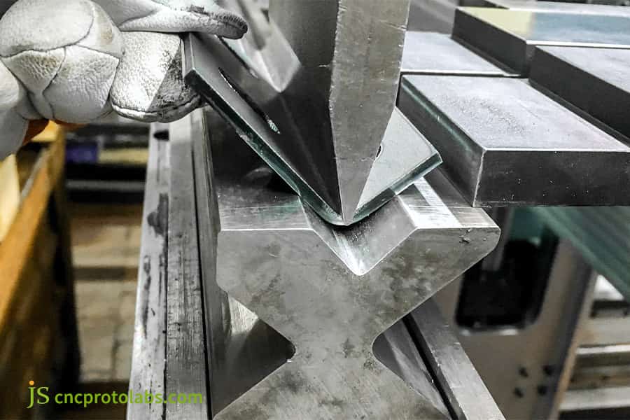
Figure 3: Worker bending lightweight metal on press brake.
How to Optimize DFM for Bending Lightweight Components to Prevent Hole Distortion and Flange Warping?
Bending lightweight components requires strict adherence to hole-edge safety-distance formulas and the use of laser relief notches in the bend transition zone to block plastic-flow stress from propagating into adjacent holes and flanges.
Four Implementable DFM Engineering Guidelines
- Minimum bending flange height: H ≥ 2t + R, to ensure stable clamping of the mold presser foot and prevent warping of thin-walled flanges.
- Maximum permissible distance from the edge of the hole to the tangents of inner rounded corner of the bend, is D of ≥ 2.5t + R, a requirement to be sure the hole is no longer elliptical by stretch.
- Rectangular and semicircular relief grooves can be considered as means for stress concentrating zones releasing tensile stress along the outer side of a bend and also preventing initial microcrack formation.
- Secondary stamp features like countersunk holes and bulges should be done either (for holes) before or after (for bulges) bending so as not to disturb the feature dimensions due to plastic flow during forming.
Lightweight part bending DFM geometric limit parameters
|
Sheet Thickness t (mm) |
Min. Flange Height Hmin (mm) |
Min. Hole-to-Bend Distance Dmin (mm) |
Relief Notch Width × Depth (mm) |
Over-Limit Deformation Risk |
|---|---|---|---|---|
|
0.8 |
3.4 |
3.7 |
1.2 × 1.5 |
Hole ovality > 0.15 mm |
|
1.2 |
5.0 |
5.5 |
1.5 × 2.0 |
Flange warping / crack |
|
2.0 |
8.0 |
9.0 |
2.0 × 3.0 |
Through-thickness crack |
Based on JS Precision's in-house DFM database (2023–2024), hole-to-bend distances of D ≥ 2.5t + R keep hole ovality below 0.15 mm across 0.8–2.0 mm sheets; tighter spacing requires laser stress-relief notches.
How Do CNC Press Brakes, Stamping, and Panel Benders Compare for Custom Metal Bending Service?
Metal bending service for 1–5,000 piece low-volume custom orders favors CNC press brakes and flexible panel benders, which require zero dedicated tooling and change over in minutes, delivering lower total cost than progressive stamping tooling for small batches.
Technology and cost boundaries of the three processes
- CNC servo custom batch bending solution: mold investment $0 (universal mold library), the line changeover is in minutes, tolerance ±0.05 mm, suitable for parts that vary a lot, small batches and parts with flanges.
- Flexible bending center (Panel Bender): Robotically automatic feeding + top and bottom bending, the line changeover is in minutes, suitable for a sheet which are of a very big flat size and multiple bending edges, single-piece cycle time is better with bending machine.
- Continuous stamping tooling: mold investment of more than $20,000 changeover time of an hour, suitable for 10,000 or more quantity of mass production of the cycle with almost lowest unit cost.
Multi-variety small-batch customization process selection decision
|
Process / Criterion |
CNC Servo Press Brake |
Flexible Panel Bender |
Progressive Stamping Tooling |
|---|---|---|---|
|
Tooling Investment (USD) |
0 |
0 |
20,000+ |
|
Changeover Time |
Minutes |
Minutes |
Hours |
|
Optimal Batch Size (pcs) |
1 – 5,000 |
1 – 5,000 |
10,000 – 1,000,000+ |
|
Tolerance Reproducibility |
±0.05 mm |
±0.05 mm |
±0.02 mm |
|
Complex Flange Adaptability |
High |
Medium |
High |
Based on JS Precision's internal production data (2024), CNC press brakes and panel benders achieve lower total cost than hard tooling stamping in sub-5,000-piece custom batches.
Break-even analysis: if the annual demand is more than about 8,000–10,000 units, amortization of progressive stamping tooling gets higher than the saving you get by the per-piece lower cost of labor from CNC bending; yet, below that range, the lowest-cost technology would be the use of CNC press brakes and panel benders.
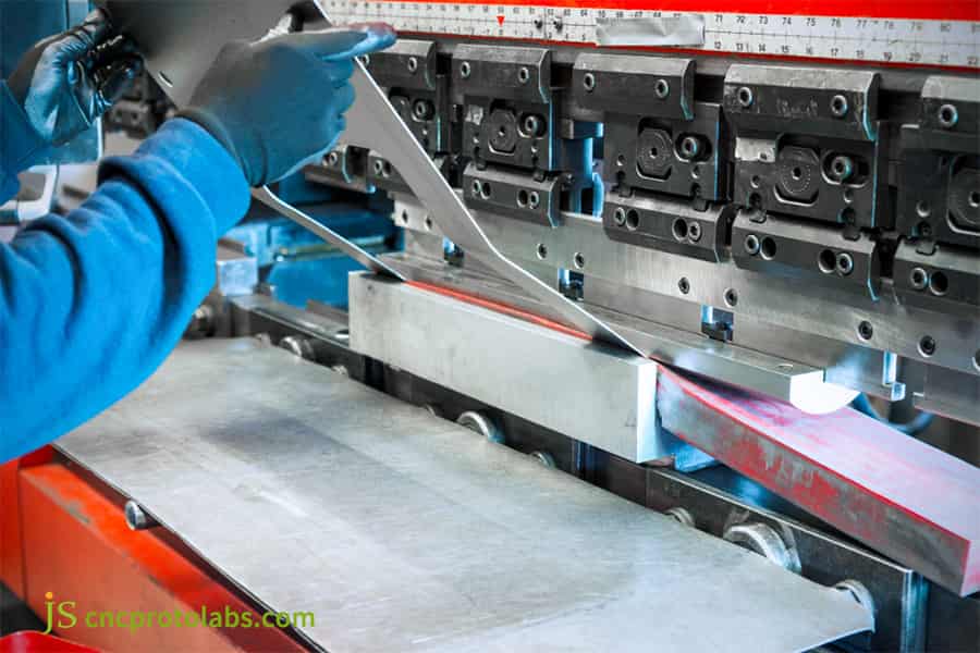
Figure 4: Worker using CNC press brake for metal bending.
JS Precision Case Study: Multi-Curvature Precision Bending for Lightweight Titanium Medical Robotic Arms
Difficulties encountered by customers
A European medical device company built a small robotic arm casing out of 1.0 mm Grade 5 (Ti-6Al-4V) titanium alloy, with features including a 7-part complex parts bending sequence and 12 heat dissipation holes arranged at high density. The original supplier's cold bending of the room-temperature workpiece caused microcracks on the outer bend radii (38% of parts failed penetrant testing) and stretched the holes by up to 0.35 mm.
JS Precision Solution
- Thermodynamic simulation and DFM correction: with the help of Deform-3D software for stress field simulation, the inner bending radius R was reduced from 1.5 mm to 2.2 mm under the condition of assembly dimensions being satisfied. On the hole side, a 0.8 mm laser micro cut was predetermined to relieve pressure at that part.
- Localized high-frequency induction temperature control forming: create local heating fixtures so that the material's temperature in the deformation zone is kept within the range of 280°C–320°C, this way not only the plastic elongation is enhanced but the cold brittle microcracks get removed.
- Adaptive CNC segmented pressure forming: the method uses the multi-level pressure holding curve control ( rapid descent - stepped slow pressing - pressure holding for 2.5 seconds to release residual stress) and carries out the 100% geometrical inspection of the first piece using the optical projector.
Failure experience and lessons learned
In the early stages of testing, the fast heat conduction of the mold made the temperature of the workpiece fall below 50°C, which led to an out-of-tolerance springback of 0.25° in the first two components. After investigation, the engineers decided to apply a high-temperature resistant ceramic insulating layer to the contact area of the mold to prevent heat loss, maintain the forming temperature, and reduce springback. As a result, the angular tolerance of the next samples was within ±0.08°, which demonstrated the effectiveness of the ceramic insulation.(JS Precision internal production data, 2024)
Final results
Once the process was stabilized, we produced 200 complete housing sets of housing parts for robotic arms with bent angle tolerance kept within ±0.08°. The hole distance tolerance was maintained at ±0.03 mm for critical holes, and inspection by coordinate measuring machine (CMM) yielded a 100% passing rate. As a result, delivery time for the project was cut from 4 weeks to 12 days.
Need a similar precision bending solution for multi-curvature titanium alloys? Contact JS Precision engineers for a free DFM review and customized process roadmap.
What Are the 5 Critical Criteria When Choosing a Precision Metal Forming Supplier?
When evaluating sheet metal bending suppliers, focus on CNC axis count, springback control database, inspection equipment capability (CMM / 3D scanner), and DFM engineering collaboration capability.
Five core evaluation indicators (Checklist):
- Tooling and mold manufacturing capabilities: what is your ability in developing specialized segmented molds together with non-marking tooling (acceptance criteria: can you deliver dedicated non-marking mold solutions like Roll-a-V / polyurethane gaskets)?
- Quality system certification scope: ISO 9001:2015 and IATF 16949 (Automotive/Precision Instruments) certification (Acceptance criteria: the certificates are current, and scope documents can be shown).
- Inspection equipment accuracy: The coordinate measuring machine (CMM), portable articulated arm laser probe, and surface roughness tester are all available (acceptance criteria: CMM indication error ≤ 2.5 μm + L/250).
- Rapid prototyping response capability: The mold library is a universal one capable of giving samples in 48 hours after an agreement (acceptance criteria: DFM and quotation sent out in 4 hours following STEP + 2D PDF drawings reception).
- Integrated management and control of surface post-treatment: process traceability of anodizing, passivation, and powder coating (acceptance criteria: all batches come with surface roughness and film thickness test records).
Preparing to evaluate precision metal bending suppliers? Contact JS Precision today for a free supplier evaluation checklist and a DFM manufacturability review.
FAQs
Q1: What are the primary differences in bending behavior between Aluminum 6061-T6 and 5052-H32?
Aluminium 6061-T6 with a tensile strength of ≥ 290 MPa has elongation of only 8–10%. Cold-bending causes tearing at the grain boundaries for Aluminium 6061-T6, so the minimum radius should be about 3 times the thickness (i.e., R ≥ 3t). In contrast, 5052-H32 has an elongation of 12–18%, can be bent at R = 1t, and exhibits much less springback than 6061-T6.
Q2: How does JS Precision control cumulative tolerance stack-up during multi-bend operations?
JS Precision applies an automated 8-axis bending machine capable of laser measuring the angle on the go and using pressure feedback for fine adjustments to the dead center of the press by taking into consideration the real thickness of the sheet within 0.01 seconds. With the support of a process inspection using contact-type measuring machines, the total deviation of over 5 bends stays within ±0.05 mm.
Q3: What engineering factors most significantly influence the quote for custom metal bending service?
The bending quotation is determined by the material grade, plate thickness tolerance, bending pass and interference complexity, non-marking tooling amortization fee, and testing level. When a single batch reaches 500 pieces or more, the tooling setup amortization cost can be reduced by more than 35%.
Q4: Why is it necessary to maintain a minimum hole-to-bend distance, and what is the formula?
The plastic flow of the material in the bending region can cause the adjacent hole to enlarge. The distance from the hole's edge to the tangent point of the bend's inner radius should be D ≥ 2.5t + R. If space is limited, a laser stress-relief groove should be introduced to prevent stress transmission.
Q5: What is the K-Factor in sheet metal bending, and why does it dictate flat pattern accuracy?
The K-Factor is the ratio between the position of the neutral layer during bending and the metal sheet thickness t (which usually ranges 0.3–0.5). Accurately measuring the K-Factor is essential for correct flat-pattern development for unfolding and blanking of sheet metal in CAD without error, and also for preventing out-of-tolerance shapes after the bending process.
Q6: What is the minimum sheet metal thickness achievable in precision metal forming?
Ultrathin gaskets and shielding as thin as 0.1 mm can be produced consistently thanks to high-precision CNC presses and precision grinding molds; whereas 0.1–0.3 mm ultrathin foils are usually cut with bending guide lines via photochemical etching and afterwards they will be shaped on the fixtures.
Q7: How are tooling marks and scratches completely prevented on cosmetic aluminum parts?
JS Precision uses polyurethane elastic lower mold pads, high-toughness molding protective films, or even Roll-a-V roller-type scratch-free lower molds to transform sliding friction into rolling contact and maintain the original surface roughness (Ra ≤ 0.4 μm) with zero scratches.
Q8: What is the typical lead time from CAD upload to prototype delivery at JS Precision?
After receiving CAD drawings with both tolerance data (2D) and 3D STEP files, JS Precision is ready with DFM analysis and quotation results within 2 to 4 hours; relying on its mold library, JS Precision delivers prototype tooling and first-article inspection within 48 hours.
Summary
Lightweight, high-strength alloy part fabrication quality heavily relies on robust material-anisotropy control as well as accurate springback compensation algorithms and customized tooling and dies. By incorporating DFM (Design for Manufacturing) guidelines like hole margin between edges and pressure relief grooves at an early stage and pairing them with multi-axis CNC closed-loop bending systems, a dimensional accuracy of ±0.05 mm can be reliably produced without defects caused by bending cracks, surface blemishes, and hole stretching.
Please contact JS Precision engineering if your production encounters issues like cracking during bending, tolerance stack-up, or surface marks / die marks. Simply submit your 3D CAD drawings (STEP/IGES/DXF), and the engineering team will send you a free manufacturing feasibility analysis report of DFM and step-by-step cost proposal within 4 hours.

Disclaimer
The contents of this page are for informational purposes only. For JS Precision Services, there are no representations or warranties, express or implied, as to the accuracy, completeness, or validity of the information. It is the buyer's responsibility to identify specific technical requirements and request a formal parts quotation. Please contact us for more information.
Resource

