 English



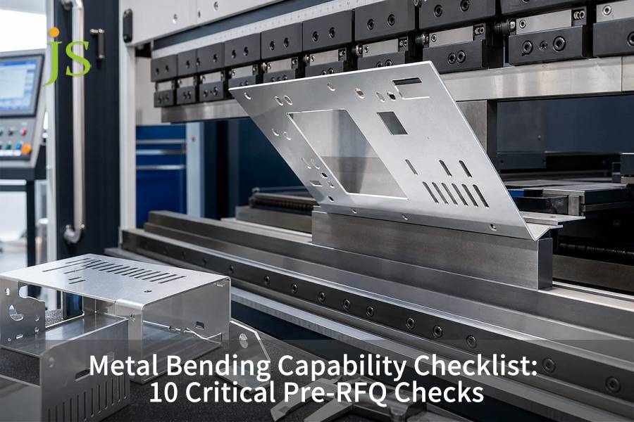

Aluminum and steel bending require trade‑offs among yield strength, springback, and bend radius (R/t). Aluminum reduces weight by 65% but exhibits 1.5–3× higher springback, needing inner radii of 1t–3t; steel needs 30%–150% more force yet supports tighter 0.5t–1t radii. Ordinary subcontractors cause 1.5°–3.0° deviations and 18% defect rates. JS Precision uses proprietary sheet-metal DFM blank-development (unfolding) methods to converge tolerances to ±0.05 mm–±0.10 mm before the drawing is frozen.
Comparison Table of Physical Defects and Engineering Compensation in Sheet Metal Bending
|
Defect Mode |
Physical Cause |
Common Drawing Out‑of‑Tolerance Manifestation |
JS Precision Prevention & Process Control Parameters |
|---|---|---|---|
|
Hole Oval Distortion |
Mounting hole in bend tangent zone |
Pin concentricity out, hole runout > ±0.25 mm |
Hole edge ≥ 2.5t + R; pre‑punch → bend → CNC reaming |
|
Outer Corner Tearing |
Bend parallel to grain without relief |
Side tension tears, edge micro‑cracks |
Relief notch width ≥ 1t, depth ≥ R + t; perpendicular grain |
|
Angle Out‑of‑Tolerance Warp |
Yield fluctuation causes springback |
Closed angle insufficient, drift 1.5°–3.0° |
DIN 6935 compensation, CNC crowning |
|
Bottomed Flange Slip |
Flange < half lower die opening |
Forming incomplete, size out ±0.20 mm |
Flange L ≥ 4t; use small‑V segmented dies |
|
Coating Assembly Interference |
No pre/post‑coating dimension defined |
Coating encroaches clearance, gap > 40 μm |
Lock tolerance as after anodizing, pre‑reserve compensation |
Source: JS Precision 2025–2026 measured database
Controlling deformation in industrial sheet metal is not simple geometric scaling. It must be designed with a safety margin based on the material's tensile yield limit and the geometric contact point of the lower die.
Key Takeaways
- Flange and hole position: Flange height ≥ 4t, hole edge distance from bending tangent point ≥ 2.5t + R, to prevent hole diameter stretching.
- Crystal orientation and radius: Minimum inner radius ≥ 1t, bending line perpendicular or 45° intersecting rolling crystal orientation.
- Tolerance stratification: standard ±0.15 mm–±0.20 mm, critical position ±0.05 mm–±0.10 mm.
What Is the Minimum Flange Length for Sheet Bending?
The minimum bending flange length is the limit straight edge dimension for stable support after the sheet metal enters the lower die V-groove. Too short a length will lead to slippage and dimensional deviations. JS Precision verification standard: L ≥ 4t, calculated based on V-groove (6t-8t), ultra-compact structures use dedicated molds.
How to Calculate Bend Allowance Before Requesting a Quote
Before requesting a quote, calculate the bend allowance and verify the minimum flange length at the same time. This is the first item on the metal bending capability checklist to ensure that L ≥ 4t to prevent lower mold slippage.
Formula: Bending allowance = π × (R + K×t) × θ / 180. Before sending the RFQ, add the unfolded drawing to confirm that the minimum flange length is within the safe range of press brake tooling.
Minimum Flange Length and Press Brake Tooling Selection
- For thin plates (t ≤ 2 mm), select a 6t V-groove.
- For L < 4t, use a dedicated small V-groove die.
The press brake tooling selection for this type should be recorded in the metal bending capability checklist.
Air Bending vs Bottoming vs Coining for Flange Stability
Air bending offers flexibility but results in significant springback; bottoming reduces springback. When selecting a process, also account for the minimum flange length's support capacity, because short flanges tend to tilt.
Tolerances ±0.20 mm can be achieved using air bending; ±0.05 mm requires press brake tooling. Both should be recorded in the bending readiness checklist and matched with press brake tooling.
|
Material |
Thickness t (mm) |
Min Flange L (mm) |
Recommended V‑Groove (mm) |
Tolerance Class |
|---|---|---|---|---|
|
Mild Steel |
1.0 |
4.0 |
6.0 |
±0.20 mm |
|
Aluminum 5052 |
2.0 |
8.0 |
12.0 |
±0.15 mm |
|
Stainless 304 |
3.0 |
12.0 |
18.0 |
±0.10 mm |
Data: DIN 6935: 2011 – Specifies bend allowance and minimum flange dimensions for cold‑formed sheet metal.
How to Calculate Hole-to-Bend Distance to Prevent Oval Distortion?
The safety distance at the hole edge determines whether stretching distortion occurs during bending. A distance less than 2.5t + R will cause a round hole to become elliptical. JS Precision initiates secondary forming for holes smaller than the threshold: pre-punching a small hole → bending → CNC reaming.
Hole Placement and Hole‑to‑Bend Distance in High‑Precision RFQ
Distance = 2.5t + R (ASME Y14.5)
Before requesting a quote, include the hole-to-bend distance when calculating the bend allowance; otherwise the hole will become stretched (oval).
The RFQ must include a distance check. Air bending, bottoming, and coining have different sensitivities to hole-to-bend distance; bottoming is more prone to distortion.
JS Precision DFM flags violations and recommends relocation or secondary processing. High-precision RFQs indicate process selection to assess risk.
Preventing Oval Distortion with CNC Reaming
- Pre-punch a 0.5 mm undersized hole near the bend. If the hole-to-bend distance is insufficient, correct it by CNC reaming.
- After bending, CNC machine to the actual position, with a roundness of ±0.02 mm. The drawing indicates the process priority.
- To calculate the bend allowance before requesting a quote, the cost of secondary reaming should be included in the quote.
|
Hole Dia. (mm) |
Thickness t (mm) |
Min Distance (mm) |
Process |
Resulting Tolerance |
|---|---|---|---|---|
|
5.0 |
2.0 |
7.0 |
Laser + Bend |
±0.10 mm |
|
8.0 |
3.0 |
10.5 |
Pre‑punch + Ream |
±0.05 mm |
Source: ASME Y14.5: 2018 – Mandates minimum hole‑to‑bend distance to prevent form distortion.
Why Must Relief Notches Be Included in Intersecting Bends?
Bending tear grooves prevent stress tearing at intersecting bends. Forced downward pressure without grooves can lead to root compression and surface cracking. JS Precision specifies a relief (tear) notch: width ≥ 1t, depth ≥ R + t.
Relief Notch Design for Crack Prevention
- Width = 1t, Depth = R + t. This relief notch design enhances sheet metal bending capabilities and prevents tearing.
- At each bend intersection, a relief groove is provided, laser-cut to ±0.05 mm. Excellent relief notch design reduces bend tearing risk by 85%.
- High-strength aluminum alloys require enlarged groove parameters to eliminate bend tearing.
Sheet Metal Bending Capabilities with Notch Integration
- The relief groove allows a tighter bend radius without cracking. JS Precision's 6 kW laser cuts the grooves in the same operation, so lead time does not increase.
- Case study: The scrap rate of robot chassis dropped from 12% to 0.8%, thanks to relief notch design that eliminated bend tearing.
Bend Tearing Analysis in Aluminum Alloys
- 5052-H32 is sensitive; the relief groove reduces peak stress by 40%. Bend tearing analysis optimizes relief notch design.
- During the DFM phase, a relief-notch check is enforced to prevent bend tearing.
- Use stepped grooves for thick aluminum plates to avoid bend tearing.
How Does Material Grain Direction Impact Tight Radius Bends?
The crystal orientation of the sheet material determines its bending crack resistance. Bending along a crystal orientation is prone to microcracks. JS Precision forces the bending line to be perpendicular or intersecting at 45°, with a compact radius of ≥1t.
Minimum Bend Radius Chart per Grain Orientation
- Parallel crystal orientation: 2t–3t; perpendicular: 0.5t–1t. JS Precision provides a minimum bend radius chart for 20+ alloys to guide grain direction bending.
- Refer to the minimum bend radius chart to avoid cracking; prioritize vertical bending.
- Special alloys are subject to an additional 0.5t allowance.
Grain Direction Bending in Aluminum 5052‑H32
Perpendicular rolling direction; otherwise, the radius increases to 3t. 5052 springback height is 1.5°–3.0°, requiring over-bending compensation. Adjust the K-factor using the sheet metal bend deduction guide.
Grain direction bending, the neutral layer offset is calculated using the bend deduction guide.
Sheet Metal Bend Deduction Guide for Anisotropic Materials
K-factor adjustment based on crystal orientation: 0.44 for parallel, 0.48 for perpendicular. 3D simulation predicts the offset. Sheet metal bend deduction guide is essential for handling anisotropy.
Record the minimum bend radius from the chart and note the K-factor correction.
|
Material |
Grain Angle |
Min Radius (t) |
Springback (°) |
K‑factor |
|---|---|---|---|---|
|
AL 5052‑H32 |
0° |
3.0 |
3.0 |
0.44 |
|
AL 5052‑H32 |
90° |
1.0 |
1.5 |
0.48 |
Source: ASTM E290: 2022 – Bend testing defining minimum radius without fracture relative to grain.
When Should You Specify Free State Versus Restrained Inspection?
The measurement method for thin-walled parts is determined by the free state and constraint inspection. Unspecified constraints are prone to false deviations. JS Precision branch: Free State (ISO 2768-m) for outer casing parts, and fixture constraints + Zeiss CMM for precision-fit parts.
Metal Bending Tolerance Standards for Inspection
- For general-purpose parts, ISO 2768-m metal bending tolerance standards specify that free state inspection should be used for non-critical parts.
- The inspector selects either free state inspection or constraint testing based on the diagram.
- In conjunction with sheet metal CMM checks , strictly adhere to metal bending tolerance standards.
Free State Inspection in Thin‑Wall Components
This method is applicable when slight deformation of the part is permissible and is 30% faster than constraint inspection. Free-state inspection is the recommended standard method in metal bending tolerance standards. When implementing this, use sheet metal CMM check sampling.
Sheet Metal CMM Check with Restrained Fixtures
- Customized aluminum fixtures are used to simulate assembly, and the report includes deviation diagrams. Sheet metal CMM checks are the final means of verifying metal bending tolerance standards.
- Precision guideways require constraint testing, which complements free-state inspection.
- Data is uploaded to the ERP system to generate a traceability report.
How Do Tolerances Differ Before and After Surface Finishing?
Surface treatment tolerance compensation refers to the pre-deduction of coating thickness during bending. Anodized coating: 25–50 μm per side; powder coating: 60–120 μm. JS Precision dual-track control: 3D deduction before bending, as indicated by the caption after coating.
Post‑Finish Tolerances for Anodized Parts
- 0.05 mm anodizing on each side. Post-finish tolerances control is an extension of sheet metal bending capabilities.
- Confirm thickness with surface treatment to improve bending capabilities.
- Hard anodizing >50 μm, add 0.02 mm margin.
Plating Thickness Allowance in Bending Deduction
Zinc plating 8–15 μm; adjust by 0.01 mm for every 10 μm. JS Precision uses X-ray thickness measurement. Precise plating thickness allowance prevents interference. Incorporate 3D deductions to ensure post-finish tolerances.
Sheet Metal Bending Capabilities with Coating
- The pre-bending radius takes into account coating buildup and ERP coordination.
- Post-finish tolerances and plating thickness allowances need to be reserved to demonstrate bending capabilities.
- Apply anti-stick tape to the powder coating bending die.
Which Press Brake Tonnage Limits Your Part Geometry?
Insufficient bending machine tonnage caused an angle deviation exceeding 2°. JS Precision calculation: P = (650 × S × L × t²) / V. Adjust the bottom pressure/imprint pressure by 3–5 times; load rate <75%.
Press Brake Tonnage Calculation Formula
- S = tensile strength, L = length, t = thickness, V = width of the V-groove. Example: 2 mm steel 1000 mm → 108 tons. Press brake tonnage calculation is crucial for thick plate bending.
- Quickly assessing the load on the open bending is the first step in thick plate bending planning.
- The strength of high-strength steel is multiplied by a coefficient of 1.3.
Air Bending vs Bottoming vs Coining Tonnage Needs
Air bending 1×, bottoming 3×, coining 5×. The tonnage difference between air bending, bottoming, and coining is significant, affecting the selection of thick plate bending.
Coining is highly accurate but has a large tonnage; press brake tonnage calculation must be performed in advance.
Thick Plate Bending and Machine Rigidity
- For thicknesses greater than 6 mm, use a 500-ton machine tool with crown compensation. Thick plate bending depends on press brake tonnage calculation and process matching.
- Optimize load distribution for 8-axis CNC bending machines.
- Composite processes reduce tonnage while maintaining precision.
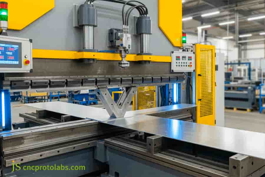
Figure 1: Press brake machine bending large sheet metal part in fabrication workshop.
How to Choose a Sheet Metal Bending Supplier for Tight Tolerances?
High-precision suppliers need to possess metal bending design for manufacturing (DFM) analysis, multi-axis equipment, and closed-loop quality control. JS Precision offers 4-axis stop, angle coding, K-factor simulation, and CNC secondary machining.
How to Choose a Sheet Metal Bending Supplier for Tight Tolerances
- Verification equipment: 4+ axes, crowned, angle-coded. Use the DFM tooling checklist to evaluate how to choose a sheet metal bending supplier for tight tolerances.
- DFM Response Time: JS Precision delivers within 2 hours, which is key to choosing a sheet metal bending supplier for tight tolerances.
- Review the DFM tooling checklist to cover parameters and refine how to choose a sheet metal bending supplier for tight tolerances.
DFM Tooling Checklist for Procurement
- Confirm V-shaped molds (6t–12t), rotating attachments, and industry case studies. Use the DFM tooling checklist to help evaluate suppliers.
- Determining the mold model is a priority item for consultation.
- Regularly update the DFM tooling checklist.
Quotation List
| Part Type | MaterialMaterial | Material | Qty (pcs) | Est. Unit Price (USD) |
| Bracket / Flange | Mild Steel | ±0.20 mm | 50–200 | $3.5 – $6.0 |
| Bracket / Flange | Aluminum 5052 | ±0.15 mm | 50–200 | $4.0 – $7.5 |
| Precision Frame | Stainless 304 | ±0.10 mm | 10–100 | $12 – $22 |
| High-Precision Part | Any (DFM rework) | ±0.05 mm | 1–50 | $25 – $45 |
Indicative range for reference; final quote after DFM review (within 2 hrs). Tooling & finishing (anodize/powder) quoted separately.
Talk to a bending engineer about your tolerance stack-up → [Get a Free Quote].
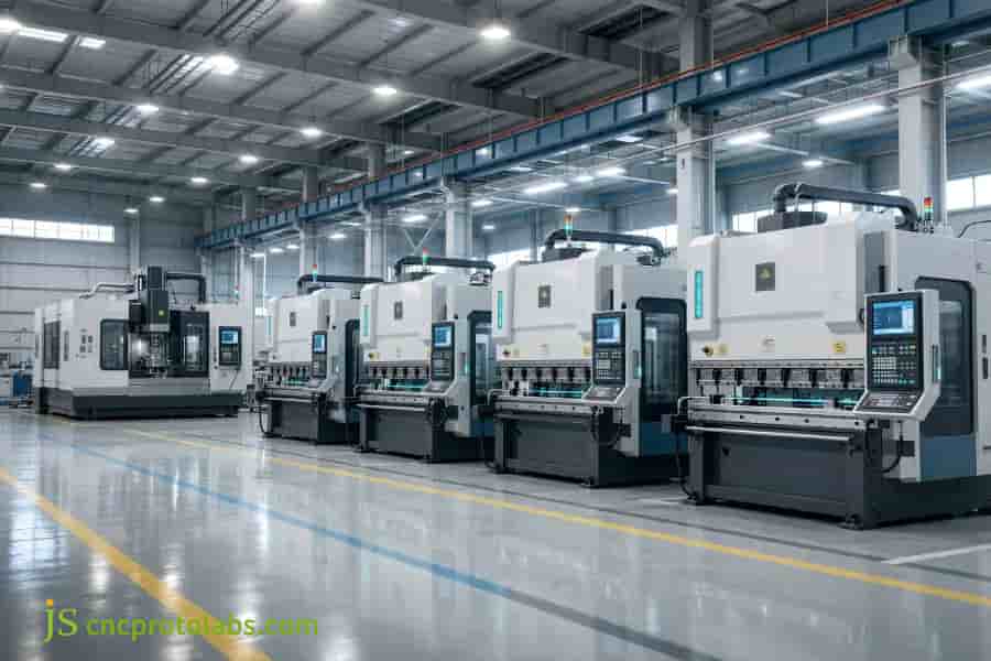
Figure 2: Row of CNC press brake machines in sheet metal fabrication supplier workshop.
Case Study: Zero‑Defect Flange Alignment for Industrial Robotics
Challenges and Solutions
The previously outsourced #ROBOT-2026-C84 chassis showed a 2.5° bend-angle deviation and hole distortion, resulting in an assembly defect rate of 18% and a 14-day delay.
JS Precision performed DFM, corrected K‑factor to 0.44, optimized V‑opening to 8t, rotated bend lines 90° to grain, added bottoming shims.
Quantified Result and Hidden Value
Flange parallelism improved to ±0.05 mm; defect rate dropped to 2%; lead time reduced to 8 days (42.8% faster); 22% cost reduction.
100% CMM pass per ISO 2768‑m; survived 1 million vibration cycles with zero deformation.
Customer Testimonials
- JS Precision's DFM saved our robot project. ±0.05 mm bends fit perfectly. – European Automation.
- Scrap rate vanished, delivery predictable. – Medical Device OEM.
- Unmatched tight‑tolerance aluminum bending. – U.S. Aerospace.
FAQ
Q1: What standard K‑factor should be used for mild steel air bending?
Use K‑factor = 0.44 for mild steel air bending (R/t ≈ 1). JS Precision fine‑tunes per batch for ±0.02 mm accuracy per DIN 6935.
Q2: How does JS Precision compensate for springback in AL 5052‑H32?
JS Precision uses 1.5°–3.0° over‑bend and real‑time laser feedback to counteract AL 5052‑H32 springback, achieving ±0.05° accuracy.
Q3: Can laser‑cut holes be placed close to the bend radius without distortion?
No, maintain ≥2.5t + R from bend tangent. If closer, JS Precision uses post‑bend CNC reaming for ±0.02 mm roundness.
Q4: What is the typical metal bending tolerance achieved by JS Precision?
JS Precision holds ±0.15 mm–±0.20 mm (conventional) and ±0.05 mm–±0.10 mm (precision), validated by Zeiss CMM per ISO 2768‑m.
Q5: Why is V‑die opening selection critical before RFQ submission?
V‑die opening sets radius, tonnage, and finish. JS Precision uses 6t–8t for t ≤ 3.0 mm to prevent slip, avoiding tooling changes.
Q6: What is the minimum bend relief dimension required for 2.0 mm aluminum?
For 2.0 mm aluminum, the relief notch requires a width of ≥2.0 mm (1t) and a depth of ≥R + t. DFM software automatically applies these features to prevent tearing.
Q7: How does coating thickness affect post-bend hardware insertion?
Powder coating (60–120 μm per side) can cause interference with inserts. JS Precision adjusts bend deductions and pre-machines holes to ensure a flush fit.
Q8: Can variations in material batch thickness alter the bend angle?
Yes, thickness variations amplify springback; JS Precision employs in-line sensing and adaptive crowning to maintain consistency within ±0.2°.
Summary
Sheet metal bending tolerance fulfillment is based on material crystal orientation, rebound and mold dynamics compensation. Select JS Precision process with metal bending design for manufacturing (DFM) to eliminate batch rework.
Are your chassis or frame suffering from corner tearing? Click to upload 2D/3D drawings, and JS Precision will provide a DFM report and quotation within 2 hours!

Disclaimer
The contents of this page are for informational purposes only. For JS Precision Services, there are no representations or warranties, express or implied, as to the accuracy, completeness, or validity of the information. It is the buyer's responsibility to identify specific technical requirements and request a formal parts quotation. Please contact us for more information.
Resource

