 English



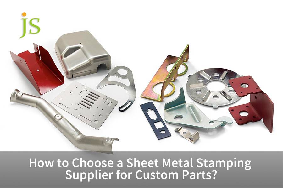

Custom metal stamping is a cold-forming process that converts flat sheet metal into complex 3D components via dedicated tooling. It utilizes specialized dies to apply pressure exceeding the material's yield strength, enabling shearing, bending, and deep drawing with tolerances controlled within ±0.02 mm. This method is suitable for high-volume, high-precision production in the automotive, electronics, and medical industries.
Summary of core answers
Custom metal stamping achieves micron-level tolerances by combining precision tooling clearances, multi-station progressive transfer, and controlled cold plastic deformation for ultra-high-speed mass production.
|
Stamping Dimension |
Key Engineering Mechanism & Control Parameters |
Industrial Manufacturing Standards & Output Boundaries |
|---|---|---|
|
Tooling |
Upper and lower die mating, single-side cutting clearance 5%–10% t, guide-post fit tolerance ≤0.003 mm, insert hardness 58–62 HRC(Rockwell C hardness) |
Control burnish zone ≥50%, eliminate excessive burrs, withstand million-level stroke loads |
|
Process |
Coil leveling → servo feeding → pilot-pin correction (positioning tolerance ±0.01 mm) → cutting/forming → strip separation |
Operating rhythm 200-800 SPM, eliminate pitch accumulation error, achieve full automation |
|
Part Forming |
Shearing, V/U bending (R/t≥1.0, over-bend compensation 1°-5° springback), multi-stage progressive deep drawing (LDR 1.8-2.1, where LDR = limiting drawing ratio, the max blank-to-cup diameter ratio) |
Dimensional tolerance DIN 6930-2 f class (±0.02 mm), material utilization 75%-90% |
Data Source: DIN 6930-2:2011, Precision stamped steel parts — Tolerances and technical delivery conditions.
What Is a Metal Stamping Die and How Does It Cut Metal?
Metal stamping tooling is a precision tool steel assembly that cuts sheet metal through controlled mechanical shear within a calibrated clearance of 5%–10% material thickness.
Core components and fit of the die
The core components of the die include upper and lower die bases, ball-bearing guide pillars and bushings (fitting tolerance ≤0.003 mm), stripper plate, and punch-and-die inserts (AISI D2/DC53, 58–62 HRC). The upper and lower mold bases bear pressure, and the guide pillars prevent off-center loading; the stripper plate eliminates material packing during punch retraction; the punch and die are made of high-hardness tool steel to ensure a lifespan of millions of strokes.
Punching Mechanics and Clearance Control
The four stages of punching are: elastic deformation, plastic shearing (bright band ≥50%), crack propagation and fracture, and terminal burrs.
The single-sided clearance c = (5%–10%) × t; too small a clearance leads to misalignment of the upper and lower cracks and chipping; too large a clearance results in larger corner collapse and rough burrs. The die uses upper and lower cutting edges to "punch" the metal within a specific clearance, and the clearance determines the edge smoothness.
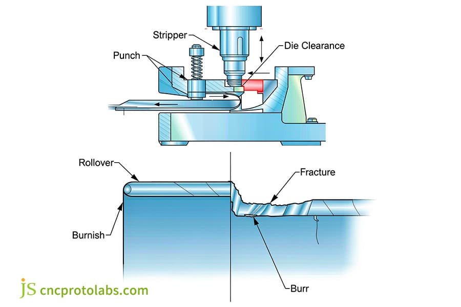
Figure 1: Diagram of metal stamping die tooling cutting sheet metal showing punch and clearance.
What Are the Critical Steps in the Metal Stamping Process?
The metal stamping process follows five systematic phases: automated uncoiling and leveling, servo roll feeding, progressive die stamping, in-line vision inspection, and secondary surface finishing. In modern progressive die setups, coil stock advances incrementally through sensor-monitored pilot stations that register positional accuracy within ±0.01 mm before high-speed mechanical presses execute progressive shearing and cold deformation cycles at speeds reaching 200 to 800 strokes per minute.
Uncoiling & Leveling:
Coil stock passes through a leveler to eliminate residual rolling stresses, ensuring the sheet flatness is ≤0.20 mm/m before entering the die. This step is crucial for preventing cumulative feed errors and laying the foundation for high-precision stamping; it is particularly effective in preventing feeding jams when handling ultra-thin strip materials.
Servo Roll Feeding:
CNC servo rollers feed the material at a preset pitch, synchronized at the millisecond level with the press crankshaft's rotation angle, ensuring feed accuracy within ±0.01 mm. This stage incorporates photoelectric sensors to detect double-feeding and prevent die damage caused by material overlap.
Pilot Pinning:
Pilot holes are pre-punched along the strip edge; tapered pilot pins fine-tune and lock the position before the die closes, tightening the positioning tolerance to ±0.01 mm. This completely eliminates cumulative errors and ensures that feature deviation at the final station remains under 0.02 mm.
Multi-Station Tooling Execution:
The press operates at high speeds of 200–800 SPM(strokes per minute), sequentially performing operations such as scrap trimming, embossing, bending, and coining. Compared to traditional mechanical presses, modern servo presses offer a 30% improvement in bottom-dead-center repeatability and significantly enhanced stroke adjustability to meet varying forming height requirements.
Part Cut-off & Inspection:
Finished parts are separated from the carrier strip, and critical dimensions are screened by a high-speed CCD vision system to ensure 100% quality compliance. Non-conforming parts are automatically ejected into the scrap bin via compressed air, enabling fully automated, unattended production.
|
Parameter |
Conventional Mechanical Press |
Modern Servo Press |
High-Speed Hydraulic Press |
Transfer Press |
|---|---|---|---|---|
|
Tonnage Curve |
Fixed near bottom dead center |
Adjustable throughout stroke |
Constant tonnage available |
Fixed, high tonnage |
|
Bottom Dead Point Repeatability |
±0.1 mm |
±0.02 mm |
±0.05 mm |
±0.1 mm |
|
Stroke Adjustability |
No |
Yes, programmable |
Yes, via limit switches |
No |
|
Max SPM |
200-400 |
200-800 |
50-150 |
15-40 |
|
Die Change Time (min) |
30-60 |
10-20 |
20-40 |
60-120 |
Data Source: JS Precision Internal Process Database (2023), based on 150+ stamping projects.
Stamping is like a miniature assembly line, with metal strips moving step by step and the stamping press forming the product in sequence, resulting in the finished product at the end.
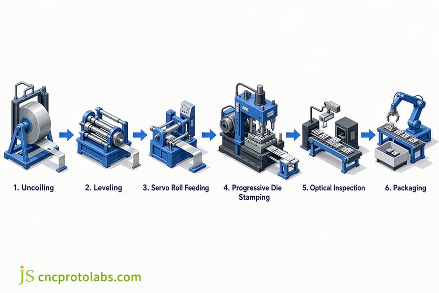
Figure 2: Flowchart showing metal stamping process steps from uncoiling to packaging in factory.
How Does Part Forming Transform Sheet Metal into 3D Geometry?
Stamped parts achieve complex 3D shapes via localized stress that exceeds yield strength but stays below ultimate tensile strength.
Shear separation
Pure shear stress dominates, with a gap of 5%–10% t, a bright band of ≥50%, and the cutting edge needs to be reground by 0.02–0.05 mm every 100,000–200,000 strokes.
Contour bending
The outer side is under tension and the inner side is under compression. K-factor 0.33–0.50 (K-factor = the ratio of the neutral-axis location to sheet thickness in bending), R/t≥1.0 to prevent cracking; springback 1°–5°, requires over-bending compensation or indentation.
Continuous deep drawing
LDR 1.8–2.1, pressure ring face pressure 1.5–3.0 MPa anti-wrinkle. JS Precision uses stepped deep drawing for connector-housing mass production, reducing the deep-drawing operations for SUS304 from 4 to 2 while reaching an 85% material-utilization rate. In the process planning stage, clarifying the boundary conditions between sheet metal stamping vs deep drawing can avoid cost waste caused by incorrect selection.
|
Material |
Tensile Strength (MPa) |
Yield Strength (MPa) |
Elongation (%) |
Recommended Min Bend Radius (R/t) |
Springback Compensation (°) |
|---|---|---|---|---|---|
|
C5191 Phosphor Bronze |
390-510 |
250-350 |
15-25 |
0.8 |
2-3 |
|
5052-H32 Aluminum |
210-260 |
130-180 |
7-12 |
1.0 |
3-5 |
|
SUS304 Stainless Steel |
520-720 |
210-310 |
40-50 |
1.0 |
4-6 |
|
DC01 Cold Rolled Steel |
270-410 |
140-280 |
28-35 |
0.5 |
1-2 |
|
Brass C2600 |
300-420 |
150-250 |
35-45 |
0.6 |
1.5-2.5 |
Data Source: ASTM B103/B103M-19 Standard Specification for Phosphor Bronze Plate, Sheet, Strip, and Rolled Bar.
The forming process permanently deforms the sheet without tearing it; the die must be deliberately over-bent by a few degrees to counteract springback.
How Do Progressive Die Applications Compare to Alternative Stamping Methods?
Progressive die stamping integrates multi-stage operations into a continuous coil-fed station array, outperforming compound dies and transfer presses in high-speed, high-volume production. While compound dies execute single-stage blanking and piercing for flat parts, progressive dies produce intricate, tight-tolerance components exceeding 100,000 units annually across automotive powertrain harnesses, medical sensor shields, and micro-electronic connectors with zero inter-station transfer misalignment.
- Progressive die: continuous roll feed, carrier series, 200–800 SPM, annual production ≥50,000 pieces, pitch accuracy ±0.01 mm.
- Compound die: single-station concentric blanking and punching, coaxiality ±0.01 mm, unable to process three-dimensional bending.
- Transfer die: After blanking at the first station, the part is transferred by a robotic arm, 15–40 SPM, suitable for large-size deep-drawn parts.
Metal stamping applications include automotive powertrain harnesses, medical sensor shields, and micro-electronic connectors. Examples include 1.20 mm tin-plated copper busbars (±0.03 mm) and 0.20 mm nickel silver shields (coplanarity ≤0.05 mm). Progressive dies offer high speed and consistency, making them the preferred choice for high-volume production.
Progressive dies are like miniature automated lines inside the tooling, with coiled stock feeding in and finished parts ejected at extremely high speeds.
If you are evaluating the process route and cost reduction plan for a specific project, you can refer to JS Precision's Precision Metal Stamping Services Complete Guide to compare the mold life curve and comprehensive economic cut-off point under different batches.
FAQs
Q1: What is the minimum bend radius required for custom metal stamping?
For low-carbon steel and semi-hard brass, a bend radius (R) ≥ 1.0×t prevents cracking of the outer arc; for hardened aluminum alloys or stainless steel, a radius of radius ≥ 1.5-2.5xt is required; when the bending axis is parallel to the rolling pattern, the radius must be increased by 20%-30% to prevent intergranular cracking.
Q2: How do engineers prevent burrs on stamped metal parts?
The core of anti-burr is to set the single-sided punching gap to 5%-10% of the material thickness and keep the cutting edge sharp; if the cutting edge wear exceeds 0.05mm, it will cause cracks, misalignment and excessive burrs. At that point, the die-core cutting edge must be re-ground.
Q3: What is the difference between progressive die stamping and transfer die stamping?
Progressive dies connect parts via a side carrier at speeds of 200-800 SPM, suitable for small to medium precision parts; transfer dies transfer parts after blanking at the first station using a robotic arm, specifically designed for large-sized deep-drawn components.
Q4: Which tool steels are commonly selected for metal stamping dies?
For medium-volume production, select AISI D2/DC53 cold work die steel (58-62HRC); for stamping stainless steel or producing more than 3 million stampings per year, insert tungsten carbide with a hardness of 88-92HRA into vulnerable parts.
Q5: How does springback affect stamped part tolerances?
Springback is the dimensional shift caused by elastic recovery after unloading. The springback angle of high-strength alloys is 2°-8°. Engineers simulate, calculate, and preset the bend angle, bottom-surface emboss, or reinforcing ribs to forcibly offset it.
Q6: What is the typical production volume threshold for custom stamping profitability?
The development cost of progressive dies is between $5,000 and $50,000, and the economics depend on volume. The cost can be reduced if the annual production volume is 10,000 to 50,000 pieces or more. For trial production of less than 1,000 pieces, laser cutting and CNC bending are recommended.
Q7: What are the standard dimensional tolerances achievable in custom metal stamping?
According to DIN 6930-2 grade f, the precision progressive die tolerance is ±0.02mm, and the bending angle is ±0.5°-1.0°; the fine blanking technology can improve the smoothness of the stripe to over 90%, and the hole spacing tolerance is ±0.01mm.
Q8: How does sheet metal thickness influence stamping press tonnage requirements?
The tonnage is directly proportional to the material thickness t, the shear perimeter L, and the shear strength tau (P=L×t×tau); the tonnage increases stepwise with the increase in thickness, and a 20%-30% margin should be reserved in the selection to prevent the machine from stalling.
Summary
Custom metal stamping balances dimensional repeatability, mechanical integrity, and economical high-volume production through synchronized tooling design, automated workflows, and controlled forming. Mastering clearance, pitch, and springback control ensures precise tolerances.
To go deeper on process selection, refer to our Progressive Die Stamping vs. Transfer Pressing: DFM and Cost Comparison Guide to compare die-life curves, feature-interference limits, and the economic break-even point of the two mainstream mass-production forming solutions.

Disclaimer
The contents of this page are for informational purposes only. For JS Precision Services, there are no representations or warranties, express or implied, as to the accuracy, completeness, or validity of the information. It is the buyer's responsibility to identify specific technical requirements and request a formal parts quotation. Please contact us for more information.
Resource

