 English



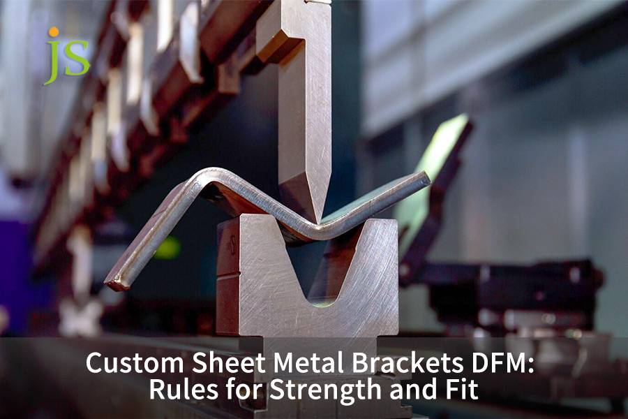

Custom sheet metal brackets fail in production for three reasons: the inside bend radius is too tight for the material's grain direction, holes sit inside the deformation zone around a bend, and cumulative tolerance across multiple bends is never compensated. Fixing all three is what keeps a bracket from cracking during forming and from jamming on the assembly line. That is why bracket DFM is not simply flattening a 3D model — each dimension you write down is a statement about yield strength, bend allowance and how much cold work the material will accept. Every threshold below is measured from production parts and expressed as a ratio of material thickness (T), so it applies at any gauge.
Core Takeaway Table: Custom Sheet Metal Brackets DFM Rules for Strength and Fit
|
Evaluation Dimension |
Core Control Parameters (Hard Physical Indicators) |
Failure Mechanism & Engineering Mitigation Rules |
|---|---|---|
|
Bend Radius (R/T Ratio) |
Mild steel / CRS: ≥ 1.0×T (bend perpendicular to grain) 5052-H32: ≥ 1.0×T perpendicular, ≥ 2.0×T parallel 6061-T6: ≥ 2.5×T perpendicular, ≥ 4.0×T parallel 304 stainless: ≥ 1.5×T perpendicular, ≥ 2.5×T parallel
|
Outer fiber overstretching causes surface microcracks; sharp-angle bending strictly prohibited |
|
Hole-to-Bend Safety Distance |
Hole outer edge to tangent ≥ 2.0×T + R; PEM nut ≥ 3.0×T + R |
Plastic flow causes hole ovalization and thread stripping |
|
Stiffness Reinforcement Design |
Stamped rib depth-to-width ratio 0.4–0.6; edge flange height ≥ 4.0×T |
Counteracts cantilever torque without increasing thickness; flexural stiffness +300% |
|
Assembly Hole Compensation |
Float clearance +0.3 mm unilateral; slot long axis ⊥ bend line |
Absorbs ±0.3 mm cumulative linear tolerance from multi-bend air forming |
|
Surface Coating Tolerance |
Powder coat reserve 80 μm; hard anodize reserve 25 μm |
Prevents bolt hole and shaft hole shrinkage/interference after finishing |
Dimensional interchangeability across a batch is governed by general tolerances rather than by any single forming standard. Where a drawing invokes ISO 2768-1, that class applies to the flat-pattern features; the bent dimensions quoted in this article are instead reported as measured process capability, sampled from 1,200 brackets produced at JS Precision during 2025.
Optimizing the bending radius ratio, reserving characteristic deformation zones, and configuring elongated oval holes on the assembly side dynamically are the key technical measures for achieving the dual goals: sheet metal brackets carrying the mechanical load effectively and being free of interference during the assembly of the hundreds of parts.
How to Choose Bend Radius and Grain Direction to Stop Cracking?
The minimum inside bend radius for sheet metal bracket fabrication is a structural threshold defined by material elongation and grain orientation to prevent outer-fiber tensile fracture. Mild steel and 5052-H32 require ≥1.0×T; 6061-T6 and 304 stainless need 2.5×T–3.0×T perpendicular to grain. Parallel bending reduces elongation by 45%, requiring 4.0×T. Matching punch radius with 8.0×T V-die opening maintains strain below tensile limit for high structural strength.
Mechanism of lattice slip and fracture elongation of materials
- When the sheet metal bracket strength is determined, the resistance of grain boundary slip of the 6061-T6 aluminum alloy is much greater than for the annealed 5052-H32, whereas intergranular microcracks are nucleated the moment that the strain of the outer fiber goes over 8%.
- The yield limit of SPCC cold-rolled low-carbon steel is scattered between 180–210 MPa, bending cracks occur threshold that is strongly controlled by the density of inclusion distribution and the difference of rolling texture orientation.
Forced constraints on rolling crystal orientation and bending angle
- If the bending axis is aligned with the anisotropic direction of metal grains, the sheet metal will show 45% less elongation at the fracture point, microcrack will spread along the grain boundaries much faster, leading to the direct reduction of fatigue life.
- A lower die with a special opening of 8.0×T for a specific sheet thickness is developed in such a way to minimize bending tensile stress on the outer side due to narrow V-die.
| Material | Condition | Min inside radius, bend ⊥ grain | Min inside radius, bend | Practical note |
| Mild steel (SPCC / CRS) | cold-rolled | 1.0×T | 1.5×T | Most forgiving; still check coil direction on tight radii |
| Aluminium 5052-H32 | strain-hardened | 1.0×T | 2.0×T | Best choice when the bracket needs a tight radius |
| Aluminium 6061-T6 | solution-treated & aged | 2.5×T | 4.0×T | Anneal to 6061-O to reach 1.0×T, then re-age to T6 |
| Stainless 304 | annealed | 1.5×T | 2.5×T | Springback, not cracking, is usually the limiting factor |
Values assume a V-die opening of 8×T. Halve the V-die opening and the required radius rises sharply because outer-fibre strain increases.
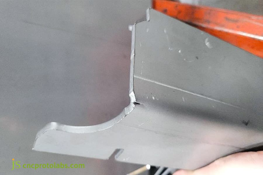
Figure 1: Cracked metal part corner after bending process.
How Do Ribs and Flanges Optimize Sheet Metal Bracket Design?
Gusset ribs and stiffening flanges increase structural moment of inertia without increasing thickness. A stamped rib features depth 0.4×T–0.6×T with root radii ≥1.0×T, oriented across the bend axis. Edge flange ≥4.0×T closes torsional shear paths, increasing flexural stiffness by up to 300% and shifting natural frequency away from low-frequency resonances.
Stamping stiffener geometry forming specifications
- The core principles of sheet metal bracket design are: root transition radius R1 ≥ 1.0×T, crest radius R2 ≥ 1.5×T, and depth between 0.4×T and 0.6×T. Beyond about 0.6×T the rib stops adding section modulus and starts thinning the parent material, which is where we see cracking in high-strength alloys.
- In JS Precision's 2025 industrial chassis bracket programme, two triangular ribs stamped to 0.5×T depth lifted the first cantilever resonant frequency from 120 Hz to 260 Hz. Adding edge flanges as well took the same bracket to 380 Hz — a 3.2× shift that also cut measured deflection under a 500 N load from 2.40 mm to 0.35 mm (see table below). Flanges contribute more than their mass suggests because they shorten the effective free length of the cantilever as well as raising its second moment of area.
Edge flange closed stress path
- The minimum edge folding height is 4.0×T, which is able to construct a closed tension-compression path. This design can effectively resist torsional loads, and fully meet the sheet metal bracket design rules.
- Ribs and flanges solve different problems.Ribs raise the second moment of area along the span; flanges close the free edge against torsion. The step change comes from using both (+340% stiffness for +8% mass), not from choosing between them.
- Check both features against your tooling before you freeze the drawing: ribs deeper than 0.6×T or flanges taller than 8×T usually need a custom punch profile and a second hit, which adds cost without adding much stiffness.
|
Structural Configuration |
Weight Increase (%) |
Section Moment of Inertia (cm⁴) |
Deflection @ 500 N (mm) |
1st Resonant Frequency (Hz) |
|---|---|---|---|---|
|
Flat Plate (Baseline) |
0 |
4.2 |
2.40 |
120 |
|
Stamped Ribs Only |
3.5 |
11.8 |
0.85 |
260 |
|
Edge Flange Only |
5.0 |
9.6 |
1.10 |
210 |
|
Ribs + Flange Combined |
8.0 |
18.5 |
0.35 |
380 |
The stiffness figures below were measured in a three-point loaded beam configuration of the type described in ASTM E855-08(2013) — which also explains why the values are derived from measured deflection rather than from nominal CAD geometry: real formed sections deviate from the idealised section, and that difference is what matters at the assembly.
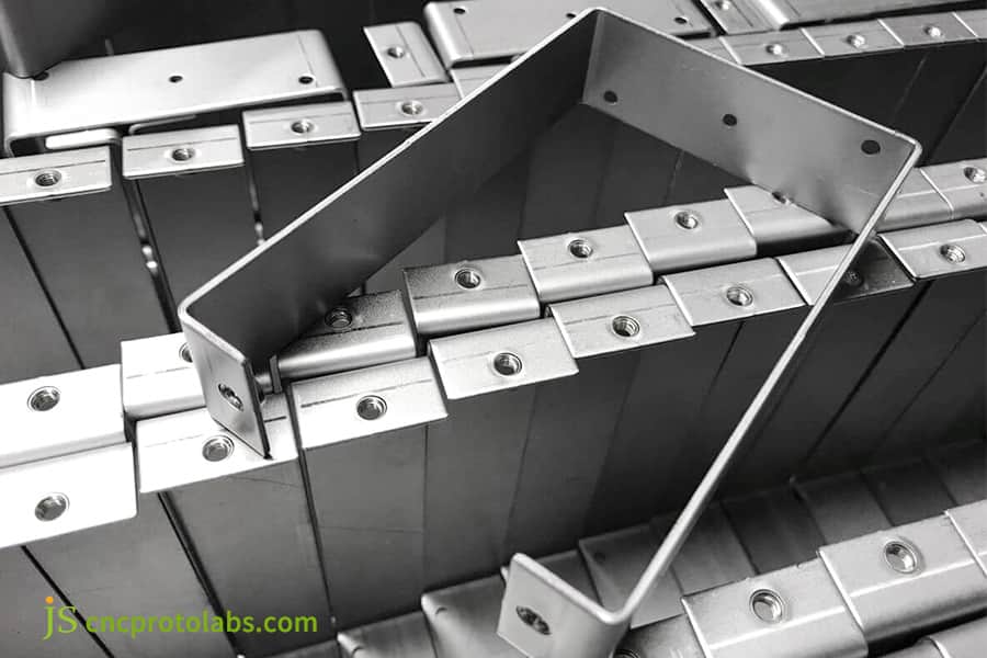
Figure 2: Metal brackets with ribs and flanges optimized.
What Is the Minimum Safe Hole-to-Bend Distance to Prevent Distortion?
The minimum safe hole-to-bend distance is the outer edge of a hole to the bend tangent line, requiring ≥2.0×T + R. Inside this boundary, plastic flows stretch holes into ovals. For PEM fasteners, clearance increases to 3.0×T + R. Cut relief tear-slots or secondary laser cutting isolates distortion.
Plastic strain field and hole wall deformation mechanism
In sheet metal bracket DFM, the main tensile stress on the outside reaches its highest value near the bending tangent point, and when the edge of the hole is located in the 2.0×T plastic deformation zone, the hole wall bulges in a round shape.
Enlarged safety clearance for press-fit nuts
- If a press-fit nut hole is also subjected to torque, the safety clearance should be increased up to 3.0×T + R to avoid the radial press-fit force being combined with a bending stress that could cause stripping of the thread teeth, this way maintaining sheet metal bracket fit tolerance.
- A larger clearance not only allows the base material to be fully compressed into the tooth groove but also ensures that the push-button force and torsional torque correspond to the rated values.
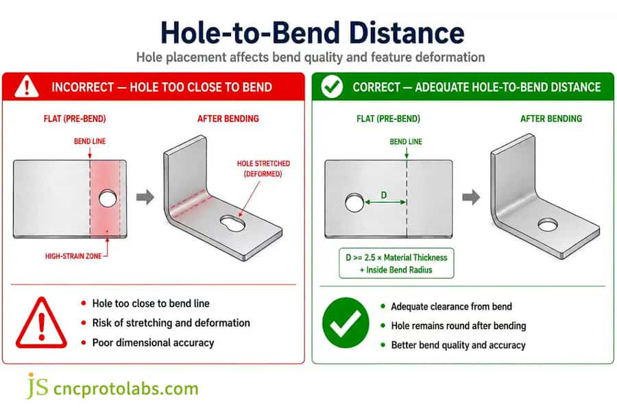
Figure 3: Diagram showing correct and incorrect hole distances.
How to Manage Bend Allowance for Perfect Sheet Metal Bracket Fit?
Bend allowance management compensates for elongation, K-factor shift, and angular drift during air forming. Sequential bending introduces ±0.5° angular and ±0.15 mm linear variation per bend. Across four bends, deviations exceed ±0.50 mm. Converting secondary holes to slotted configurations aligned perpendicular to the bend axis via L = D + 2×(∑ΔT + ∑Δθ) absorbs cumulative tolerances.
Neutral layer drift and size chain accumulation
During air bending, the difference between sheet thickness tolerance and yield strength causes the neutral layer factor (K-factor 0.38–0.45) to change continuously, so that the sheet metal bracket fit tolerance is ultimately affected.
Obtaining the formula of an elongated assembly hole
A hole downstream of several bends drifts off nominal for two independent reasons: length error from thickness variation and springback (Δt), and angular error (Δθ) resolved over distance a from the bend centre. Size the slot major axis with:
L = D + 2 × (ΣΔt + Σ (Δθ / 57.3) × a)
where D is the nominal hole diameter in mm, a is the distance from the bend axis to the hole centre in mm, and **Δθ** is the per-bend angular variation in degrees.
Worked example: D = 5.0 mm, four bends, ΣΔt = 0.30 mm, per-bend Δθ = 0.5° acting over a 20 mm arm gives Σ(Δθ/57.3) × a = 4 × (0.5/57.3) × 20 = 0.70 mm, so L = 5.0 + 2 × 1.00 = 7.0 mm — specify a 5.0 × 7.0 mm slot. Once your process is statistically capable, replace the worst-case sum with a root-sum-square (RSS) stack so the slot does not grow longer than the design allows.
Orient the slot major axis perpendicular to the bend line so it absorbs the accumulated linear tolerance instead of fighting it.
In production we close the loop rather than trust the calculation alone: the first piece of every batch gets a full CMM inspection, and the measured deviation is fed back into the bend-compensation database before the rest of the batch runs. That feedback loop — not a tighter formula — is what actually eliminates multi-hole assembly deadlocks.
What Are the DFM Rules for Standard Bend Relief Notches?
A bend relief notch is a clearance cutout at flange intersections. A bend relief notch should be at least T + 0.5 mm wide — and never narrower than 1.5 mm, whichever is greater — with the depth extending at least 0.5 mm past the bend tangent line. Omitting relief causes tearing and microcracks.Teardrop or radiused profiles decrease stress concentration factor (Kt) by ~40%, safeguarding fatigue strength.
Tearing mechanism and stress concentration factor
In custom sheet metal fabrication service, the stress concentration factor Kt at the corner transition of a rectangular crack arrestor groove is too high. A teardrop-shaped crack arrestor groove can evenly distribute tensile stress, reducing Kt by about 40%, thus meeting sheet metal bracket design rules.
Limits on the depth and width of the crack arrest groove
- The smallest width of the anti-cracking groove equals to plate thickness T plus 0.5 mm, and the depth must reach at least 0.5 mm beyond the intersection point with the bending radius.
- Modern CNC laser cutting should be equipped with a default full R-angle transition cut to prevent sharp corner cleaning and ensure the fatigue resistance of the flange bending boundary.
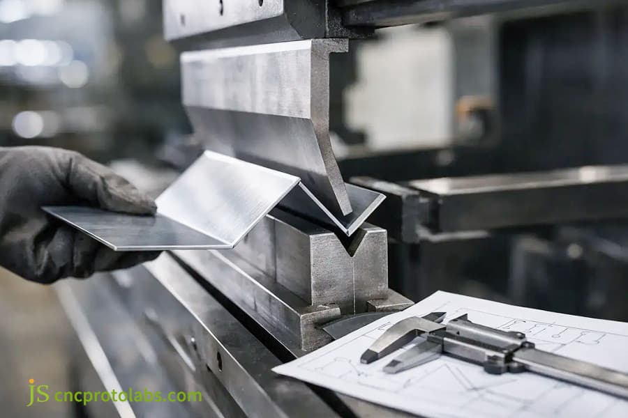
Figure 4: Worker using press brake for bending metal sheet.
What Are the Clearances for PEM Hardware in Bracket Fabrication?
PEM hardware clearances refer to separation between self-clinching fasteners and bend lines. Minimum centerline distance = D/2 + 2.5×T + R.Closer positioning deforms host holes, degrading push-out force and torque-out resistance by >60%. Specialized relieved tooling or post-bending insertion guarantees integrity.
The stress nature of press-fit fasteners
In sheet metal bracket fabrication service, holes that fall inside the plastic stretching zone around a bend no longer fill completely during installation, because the host material has already yielded there. We measure push-out force and torque-out resistance dropping by more than 60% in those holes — below any acceptance criterion we would sign off for a structural bracket.
Process interference and process route adjustment
When a collision between the fastener bottom die and the bending upper die is unavoidable, it is necessary to revise the working sequence of operations by bending first and pressing afterward, or a projection weld nut should be picked to make sure of complete lack of fastener detachment under high-frequency impact conditions.
With the operation sequence changed, the plastic shear around the fastener bore that bending used to cause disappears entirely, and the assemblies now pass the 80 G mechanical shock and vibration test without a single fastener failure.
|
Thread Size |
Sheet Thickness T (mm) |
Mounting Hole Ø D (mm) |
D/2 (mm) | Inside Radius R (mm) |
Min Centerline Clearance (mm) = D/2 + 2.5×T + R |
|---|---|---|---|---|---|
|
M3 |
2.0 |
4.2 |
2.10 | 2.0 |
D/2 + 2.5×T + R = 8.5 |
|
M4 |
2.5 |
5.4 |
2.70 | 2.5 |
D/2 + 2.5×T + R = 10.8 |
|
M5 |
3.0 |
6.5 |
3.25 | 3.0 |
D/2 + 2.5×T + R = 13.5 |
|
M6 |
4.0 |
8.0 |
4.00 | 4.0 |
D/2 + 2.5×T + R = 16.5 |
Push-out and torque-out values for self-clinching hardware come from the fastener manufacturer's own specification (for PEM parts, the applicable PennEngineering bulletin) rather than from ISO 898-1:2013, which covers the mechanical properties of carbon and alloy steel bolts and screws. Always quote the published figures for the exact part number you are installing — they vary widely with sheet thickness and host material.
Table note: clearance is measured from the fastener centreline to the bend tangent line, assuming an inside bend radius R = 1.0×T (mild steel or 5052-H32). For 6061-T6 at R = 2.5×T, add 1.5×T to each figure in the last column.

How Do Surface Finishing Coatings Impact Final Assembly Tolerances?
Surface coatings add thickness altering final dimensions. Powder coating: 60–100 μm; Type II anodizing: 10–15 μm; Type III: up to 50 μm. Neglecting build-ups causes undersized holes and misalignment. Offset cut features by 2× max coating thickness or specify masking plugs.
Coating deposition and assembly interference mechanism
Using surface treatments will change the degree of precision sheet metal bracket fit tolerance. Electrostatic powder coating deposits 60–100 μm per surface; Type III hard anodizing adds 25–50 μm. The complication is the Faraday cage effect: powder follows the field lines to outer faces and edges, while recesses, inside corners and deep holes receive little coverage — so the build-up is uneven, not uniform, and the tightest fit is usually not where you measured it.
| Finish | Build-up per surface (μm) | Design-in reserve (per surface) | Recommended action |
| Powder coating | 60–100 (typical 80) | 80 μm | Enlarge holes by 0.16 mm on diameter, or mask any hole tighter than ±0.05 mm. |
| Type II anodizing (clear or dyed) | 10–15 | 15 μm | Enlarge holes by 0.03 mm on diameter. |
| Type III hard anodizing | 25–50 | 50 μm | Enlarge holes by 0.10 mm on diameter; always mask threads. |
| Zinc plating | 5–12 | 12 μm | Usually negligible; mask threaded features only. |
Engineered shading and film thickness compensation scheme
- Precision grounding copper areas, hinge pin holes, and small-diameter threads (≤ M4) must be made with high-temperature silicone engineering shielding process.
- Compensate in the flat pattern before the part is cut. Because film builds up on both faces of every internal contour, enlarge cut holes by 2 × the maximum expected coating thickness and reduce external tabs by the same amount. For features held tighter than ±0.05 mm — threads, grounding pads, dowel holes — do not compensate geometrically at all; mask them.
Case Study: How a 6061-T6 LiDAR Bracket Went From 100% Rejection to a 99.8% Pass Rate?
JS Precision optimized a 2.5 mm 6061-T6 LiDAR bracket for a Tier-1 supplier. Initial prototypes had grain fracture and 0.45 mm bore drift across five bends (100% rejection). Solution: rotated blank 90° perpendicular to grain, expanded radius to 2.5×T, added two stamped ribs, and converted holes to 4.5×5.5 mm slots. Result: zero cracking, resonance at 380 Hz, 99.8% pass rate.
Difficulties encountered by customers
The customer's initial prototype exhibited three types of serious failures:
- Microcracks found at the outer corner of primary load-carrying bend.
- Under 80 G impact 4 M4 press-fit studs were released (failure rate 12%).
- End through hole positional deviation is at 0.45 mm which led to zero first-time assembly pass rates.
JS Precision Solution
- Rotate the layout by 90° to make the bending line perpendicular to the rolling crystal orientation; enlarge the inner radius from 1.0×T to 2.5×T.
- Stamp two anti-torsion ribs with a depth-to-width ratio of 0.5.
- Reverse the process to laser cutting → bending → secondary cold pressing and riveting.
- Change the positioning hole to a 4.5×5.5 mm elongated hole to absorb accumulated deviation.
Failure experience and lessons learned
During the first trial production, the bending deduction was only increased, and the original method was still used. But, the nuts did not hold tight as there was still relaxation due to shear stresses remaining after cutting. The lesson generalises: on high-hardness alloys, do not put a fastener inside a zone that will be formed. Either remove the feature from that area entirely or keep it at least 3.0×T + R clear of the bend — and if neither is possible, form first and install the hardware afterwards.
Final result
The rigidity of the support frame is increased by 2.8 times, and it has passed 1,500 hours of vibration and salt spray testing. The cost per unit has decreased by 22%, and a stable annual production capacity of 150,000 units has been achieved. This process has been formalized into a standard operating procedure.
Want to replicate this successful LiDAR bracket case? Contact JS Precision engineers now to obtain the same anti-deformation cutting solution, ensuring your chassis meets assembly standards on the first try!
FAQs
Q1: What is the absolute minimum bend radius recommended for 6061-T6 aluminum brackets?
It is recommended that the absolute minimum inner bend radius when bending 6061-T6 aluminum shall be controlled between 2.5×T and 3.0×T. This is when the bending line is at right angles to the rolling crystal direction. If the bending direction is parallel to the crystal direction, the inner radius should be 4.0×T. Failure to follow the minimum radii will likely result in tensile fracture of the outer fibers.
Q2: How far must holes be placed from a bend line in sheet metal bracket design?
The clearance between the outer edge of the opening and the inner tangent of the bend should be at least 2.0×T + R as the minimum safe distance. This type of clearance fully prevents the hole from getting stretched into an oval or the hole wall from collapsing due to plastic flow during bending of materials. The rivet nut hole needs to be enlarged to 3.0×T + R.
Q3: Why are slotted holes preferred over round holes in multi-bend bracket assemblies?
In multi-bending operations, the angular tolerance and thickness error of air bending can cause cumulative runout of more than ±0.3 mm at the end of the dimensional chain.The long axis of the elongated groove is perpendicular to the bending line, which can absorb the linear cumulative tolerance with geometric sliding allowance, which consistently installs first time across the batch.
Q4: How does JS Precision ensure consistent angle precision across custom sheet metal brackets?
JS Precision employs state-of-the-art CNC bending machines equipped with laser dynamic angle measurement system as well as full-worktable device. This system not only continuously monitors the rebound of the sheet metal but also adjusts the bottom dead centre of the press dynamically while forming, this way limiting the overall change in bending angle at ±0.2°.
Q5: What is the optimal width and depth for bend relief cuts in custom sheet metal brackets?
Width the notch to max(T + 0.5 mm, 1.5 mm) and carry its depth 0.5 mm past the bend tangent line; anything shallower leaves the tear initiation point inside the flange root. For crack propagation prevention it is generally recommended to have cracks arrested either by a fully round bottom or a teardrop shaped crack arrestor groove, this way minimising the stress concentration factor.
Q6: What factors determine the quote for a precision sheet metal bracket fabrication service?
The sheet metal bracket manufacturing quote is calculated based on a comprehensive assessment of material specifications, the total length of the laser cutting contour path, and the number of adjustments required for punching and bending processes.The quantity of press-fit fasteners, surface treatment type, and coordinate measuring machine (CMM) inspection report are all key variables contributing to the tiered pricing.
Q7: Can heat treatment prevent 6061 aluminum brackets from cracking during tight-radius bending?
Cold bending can be performed in the fully annealed state (6061-O), where the material has the best plasticity, allowing the bending radius to be reduced to 1.0×T to 1.5×T without microcracks. After forming, it is solution hardened and artificially aged to T6, but a special forming fixture must be used.
Q8: What tolerance can typically be held on CNC bent sheet metal brackets without machining?
Ordinary CNC air bending can maintain a linear tolerance of ±0.20 mm in the unfolded plane cutting feature, and the open linear tolerance between the bent flange faces is usually within ±0.35 mm. Through hard mold local correction and laser-following fine adjustment technology, it can be tightened to ±0.15 mm.
Summary
High-quality custom sheet metal brackets are a systematic manufacturing process involving material mechanics, bending radius ratios, deformation exclusion zones, and coating compensation. Adhering to R/T crystal orientation thresholds and hole avoidance boundaries completely eliminates the risks of bending cracks and assembly interference. JS Precision, relying on high-tonnage all-electric servo CNC bending machines and a complete CMM dimensional verification system, delivers brackets to a documented first-piece and CMM inspection regime to the global high-tech industrial sector.
Send your DXF or STEP drawings to the JS Precision engineering team for a detailed DFM assessment and transparent tiered pricing within 2–12 hours — including the specific bend radii, hole clearances and slot dimensions this article recommends.
Disclaimer
The contents of this page are for informational purposes only. For JS Precision Services, there are no representations or warranties, express or implied, as to the accuracy, completeness, or validity of the information. It is the buyer's responsibility to identify specific technical requirements and request a formal parts quotation. Please contact us for more information.
Resource

