 English



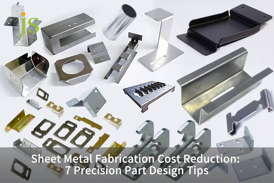

Sheet metal fabrication cost reduction is a step-by-step manufacturing approach that involves optimizing a part's design to get the most out of the materials, minimize material usage, reduce changeovers in forming tools and eliminate the costs tied to tight dimensions.
Following 7 design-for-manufacturing (DFM) rules cuts sheet metal fabrication costs by 20–35% without changing assembly performance. The following sections break down each rule with actionable guidelines, real-world data, and a case study demonstrating a 32.8% total cost reduction on a custom industrial enclosure.
The 7 DFM Cost-Reduction Rules at a Glance
|
Design Tip |
Traditional Pitfall |
DfM Optimized Solution |
Expected Cost Reduction |
|---|---|---|---|
|
Tip 1: Standard Gauge Thickness |
Non-standard thickness (e.g., 1.35mm) |
Metric standard thickness (1.0/1.5/2.0mm) |
Raw material cost ↓ 15% |
|
Tip 2: Unified Bend Radius |
Multiple different R angles |
Global uniform R = 1.0mm matching standard tooling |
Tooling changeover ↓ 50% |
|
Tip 3: Simplified Unidirectional Bends |
Multi-direction, reverse complex bends |
Bend lines in same direction/single axis |
Clamping & flipping time ↓ 30% |
|
Tip 4: Relax Non-Critical Tolerances |
Full drawing ±0.005in extreme tolerance |
Mating face ±0.05mm, others ±0.2mm |
Scrap rate 8% → 1.2% |
|
Tip 5: Standardize Hole & Bend Edge |
Hole diameter < sheet thickness or too close to bend |
d ≥ S, edge distance ≥ 2.5S |
Eliminate tearing & rework |
|
Tip 6: Streamline Surface Finish |
Multi-layer plating or custom color |
Standard powder coat (RAL) or mill finish |
Cycle & cost ↓ 25% |
|
Tip 7: Regularize Contour for Nesting |
Irregular contour generates scrap |
Rectangular or common-edge geometry |
Material utilization ↑ 88% |
Data source: NIST MEP National Network; ISO 9013:2017.
Key Takeaways
Primary idea of strategy: standardized designs eliminate changes to tooling, reasonable dimension deviations result in reduced amount of waste, simple part shapes increase nesting efficiency.
A pre-production DFM check can result in cost reduction of 20%–35%, while the assembly is still performing fine.
How to Achieve Sheet Metal Fabrication Cost Reduction via Standard Material Selection? (Tip 1)
The use of a standard sheet thickness plays an important part in sheet metal fabrication cost reduction. By using a 1.0mm, 1.5mm or 2.0mm gauge, sheets can be obtained directly from stock.
Impact of Standard Thickness on Lead Time:
Custom thickness as 1.35mm leads mills to request custom coils and the material costs increase by about 15%–25%. CRS, 304 stainless steel, and 5052 aluminum, all standard grades, are stocked by certified suppliers.
- Inventory availability: 1.0/1.5/2.0mm CRS in standard dimensions are available for immediate blanks without a delay.
- Tolerance baseline: the standard thickness tolerance ±0.08mm is defined in ASTM A480/A480M-24 for a 1.50mm cold-rolled sheet with No.2B finish which shall have maximum Ra of 0.5 micron.
- Lead time compression: it is possible to produce pieces of standard gauges within 48 hours. Custom thickness blanking takes about 12–16 days.
ASTM A480/A480M-24 specifies: Thickness tolerance for cold rolled wide plate at 1.5mm base metal shall be 0.08 mm, No.2B surface finish should limit Ra 0.5 μm.
JS Precision carries out incoming material inspection as required by ASTM A480/A480M, thereby guaranteeing standard thickness is achieved and powder coating adhesion requirements are fulfilled.
Hidden Cost Structure of Non-Standard Thickness
Based on our hands-on experience during 2026 automated cabinet project, 4 non-standard thicknesses (1.35/1.65/1.85/2.25mm) were consolidated into standard CRS 1.5mm and 2.0mm. This resulted in a 15% material cost savings and a reduction from 14 days to just 2 days in the procurement lead time.
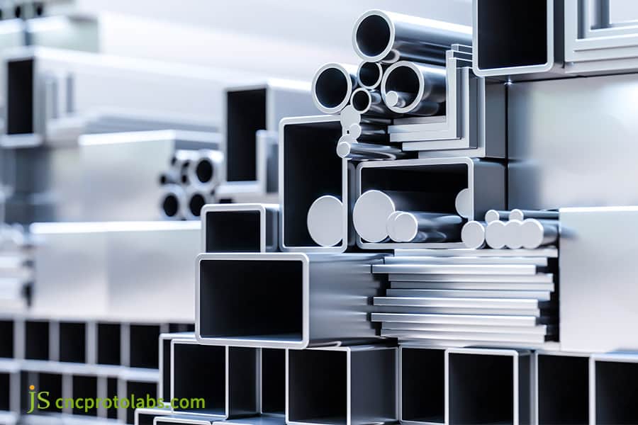
Figure 1: Various aluminum and steel profiles for sheet metal material selection.
Which Precision Sheet Metal Design Tips Eliminate Tooling Changes Through Uniform Bend Radii? (Tip 2)
Setting all internal bend radius values the same one value is one of the most important precision sheet metal design tips. Making every corner as R=1.0 mm you are eliminating the need of changing multiple tools for CNC press brakes.
CNC Press Brake Tooling Matching Logic
- R-diversity issue: Each R-angle increase of one adds about 22 minutes of non-productive setup time.
- NIST MEP data: Quick Changeover /Setup Reduction approach demonstrably reduces changeover time and shortens delivery cycles.
- Single-tooling option: Unified R = S allows one tooling setup to handle all bends.
|
Bend Radius Config |
Tool Change Count |
Setup Time (min) |
Per-Part Bend Time |
Per-Part Labor Cost |
|---|---|---|---|---|
|
4 Different R Angles |
4 |
88 |
6.5 min |
$2.40 |
|
Unified R = 1.0mm |
0 |
0 |
3.2 min |
$1.10 |
|
Cost Delta |
−4 |
−88 min |
−3.3 min |
−54% |
Data source: NIST MEP National Network; BLS April 2026 NAICS 332 average wage $33.90.
Design Execution Standard for Unified Radius
From our hands-on experience in the 2026 automated cabinet project, we observed that by unifying all the internal bend radii to R=1.0mm, we were able to compress bend time by 11.2 min per part, cutting bend time to 5.4 min per part — a 46% reduction.
- Bend radius: the inner radius should be ≥1 sheet thickness (1t). Any less will create micro cracks.
- The tooling library match: R = 1.0mm will work with the standard 8° V-die (opening 12 radius). This way, no custom tooling was necessary.
- CAM pre-check: Today's CAM software can detect the use of non-standard radii before manufacturing, and it is able to do this by comparing the DXF geometry with the shop's tooling table.
For a free drawing R-corner layout optimization from our side to minimize milling/turning labor costs - contact JS Precision structural engineers.
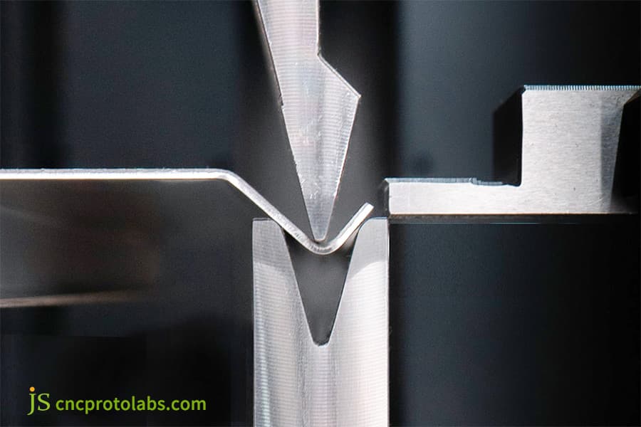
Figure 2: Press brake bending metal sheet with uniform bend radii design tip.
Why is Simplifying Bend Lines Essential in DFM Sheet Metal Design Service to Cut Labor Costs? (Tip 3)
Keeping the bend lines in the same direction is one of the main rules of the DFM sheet metal design service. From this method, flipping adjustments as well as specific fixtures are minimized.
Bend Axis Direction & Material Grain
Having bend lines in different directions increases the risk of the machine hitting each other and the operators have to flip the workpieces repeatedly to the right orientation.
- Grain direction 90° rule: to avoid micro-cracks at the outer corners, the bend axis has to be perpendicular to the Grain Direction.
- Flip time penalty: if the bends come into conflict with each other then flipping by 180 to reach the right orientation of the part, one part costs about 2–3 minutes.
- Productivity gain: Going for uni-directional bending results in saving time at manual bending by 35%.
The standard ISO 9013:2017 says: in case of laser cutting for a sheet of thickness 32 mm, Grade 1 perpendicularity tolerance u =0.05+0.003a mm, mean roughness Rz5=10+0.6a μm.
JS Precision ensures laser blanking work is done per ISO 9013:2017 Grade 1 cutting requirements, Rz5 ≤ 25 μm, edges that support consistent downstream bending.
Fixture Investment Optimization for Unidirectional Bends
Field data from our 2026 cabinet line shows that the merging of primary bending lines with single-axis co-direction results in the increase of part nesting utilization from 68% to 86% through the removal of flip fixtures completely.
- The reduction in clamping: with only one clamping step needed for unidirectional bends.
- Designing to prevent collisions: A co-directional layout supports robot multi-axis bending without collision.
- Accumulated accuracy: the backgauge repeatability ±0.005in maintains each bend angle within ±0.5° deviation of the desired angle.
Send your drawing of the complex structural parts to JS Precision where we will help you to optimize the bend path, do interference free assessment.
How to Relax Non-Critical Tolerances to Implement Design for Cost Sheet Metal Principles? (Tip 4)
Relaxing non-critical tolerances is key to design for cost sheet metal. The 0.05mm is only maintained on the areas coming into direct contact, other areas are toleranced to ±0.2mm, directly affects the scrap rates.
Tolerance Grading Strategy
A tight tolerance ±0.005 inch (approx. ±0.127 mm) forces shops to give up laser cutting and bending, and choose the slow EDW or make bespoke fixtures, so costs escalate quickly.
- Unseen tolerance costs: in BLS 2026 data metal fabricators average wage was $33.90/hr - each and every additional quality check is a concrete cost on plant floor; the tightest tolerances require three times more inspection.
- Compensation by flexibility: Sheet metal's naturally flexibility gives tolerance grading that maintains assembly quality and cuts out inspection using full CMM.
- Scrap reduction by using tolerance grading: with tolerance grading scrap was cut from 8% down to 1.2%.
|
Tolerance Application |
Traditional Blind Tolerance |
DfM Graded Tolerance |
Manufacturing Process |
Per-Part QC Cost |
|---|---|---|---|---|
|
Critical Mating Face |
±0.127mm |
±0.05mm |
Laser cut + CNC bend |
$0.85 (CMM) |
|
Non-Mating Face |
±0.127mm |
±0.2mm |
Laser cut + caliper check |
$0.12 |
|
Hole Pattern (non-asm) |
±0.127mm |
±0.15mm |
CNC punch |
$0.20 |
|
Edge Squareness |
±0.127mm |
±0.3mm |
Laser cut |
$0.08 |
|
Bend Angle |
±0.5° |
±1.0° |
CNC press brake |
$0.15 |
Data source: BLS April 2026 NAICS 332; NIST Manufacturing Cost Guide: A Primer.
Tolerance Grading Execution Framework
Per ISO 2768-1:1989 framework, critical features receive ISO 2768-fH tolerance, non-critical features release to ISO 2768-mK (medium), reducing machining cost by up to 30%.
- Three-tier zoning: Functional critical tight tolerance + controlled inspection; mating important medium tolerance; non-critical shop standard.
- CMM exemption: Non-critical faces are permitted to ±0.2mm without inspection by full CMM, reducing quality control labor dramatically.
- Scrap compression rate: 8% to 1.2% even when assembly remains the same.
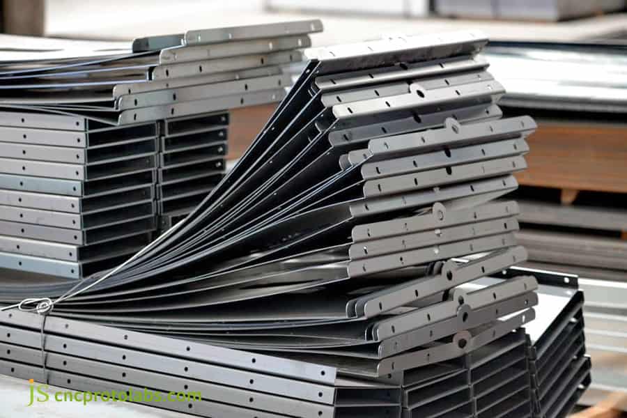
Figure 3: Batch of sheet metal brackets with relaxed non-critical tolerances.
How to Standardize Hole Dimensions and Bend Reliefs for Sheet Metal Part Design Optimization? (Tip 5)
For sheet metal part design optimization, two hole rules prevent rework: hole diameter must be at least 1× sheet thickness, and hole-to-edge distance at least 2.5× sheet thickness. Holes closer to a bend or smaller than the sheet thickness risk tearing and elliptical distortion.
Calculation Formula and Relief Slot Design
Holes located too close to the bend roots experience elliptical distortion due to the tensile stresses in bending operations.
- Distortion mechanism: Holes near bends change shape to ellipses; Rz5 ISO 9013:2017 and perpendicularity can't be achieved together.
- Relief slot provision: for holes close to the bends include a Bend Relief notch in the CAD model, the slot is at least 1 sheet thick and ends beyond the bend line.
- CNC pre-compensation: Machines adjust hole positions by accounting for the sheet's elongation and prevent geometric interference problems before the first part is trial manufactured.
Quantitative Execution of Hole Spacing Rules
For a 1.5mm thick CRS, the minimum aperture is 1.5mm and the minimum margin is 3.75mm. A 1.5mm pressure relief groove is added near the key hole of the bend, with a margin of 3S.
- Minimum hole size: d≥S; slot width S; edge distance≥1S (suggested 1.5S).
- Clearance in bend zone: hole to bend 2.5S is the conservative safety ratio
- Relief slot size: minimum width is 1 thickness; length is more than 0.5–1.0 mm beyond the bend line.
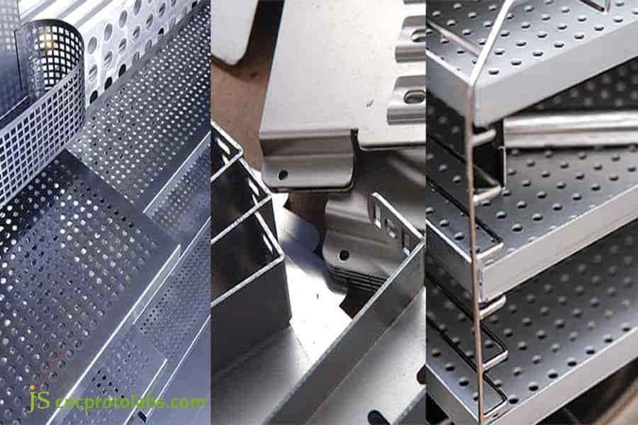
Figure 4: Standardizing hole dimensions and bend reliefs for sheet metal parts.
How to Streamline Surface Finishes to Reduce Custom Sheet Metal Fabrication Costs? (Tip 6)
The fastest way to lower custom sheet metal fabrication costs will be to simplify surface treatments. Picking the regular powder finish or factory finish, which are standard options, reduces surface treatment cost by 30% or more.
Surface treatments Cost Benchmark
Custom-colored paint, hand-brush for super finish, heavy anodizer layer, and so on not only stretch the manufacturing flow but may cause scrap as well due to color differences and color matching fees.
- Film base coating thickness: ISO 12944 system: powder coating DFT 60–80μm corresponds to 15-20 durability years of life in C3 environments.
- For internal parts: using rust stable galvanized sheet (SGCC) with a mill bright finish removes the need for a cost of any post treatment.
- As to external enclosures: standard industrial color RAL 7035 helps avoid a color-matching cost; salt spray as ASTM B117 up to 500–1000 hours.
|
Surface Treatment |
Coating Thickness |
Corrosion Resistance |
Relative Cost Index |
Typical Application |
|---|---|---|---|---|
|
Standard Powder Coat (RAL) |
60–120 μm |
Salt spray 500hr (ASTM B117) |
1.0× (baseline) |
Enclosures |
|
Anodizing (Type II) |
10–25 μm |
Salt spray 700hr |
1.8× |
Aluminum parts |
|
Electropolishing |
0.5–2 μm |
Passivation only |
2.4× |
Medical, food-grade |
|
Zinc Plating |
5–15 μm |
Salt spray 200hr |
1.2× |
Internal steel brackets |
|
Chemical Passivation |
0.1–0.5 μm |
Salt spray 150hr |
0.9× |
304/316 stainless |
Data source: ISO 12944; ASTM B117; SSPC-PA 2.
Execution Path for Surface Treatment Streamlining
In the same 2026 cabinet project, we saved surface treatment cost by 31% per-part when replacing of 28 weld seams with PEM self-clinching studs and changing to RAL 7035 powder coat.
- Visual inspection only at cosmetic face: non-visible faces are excluded from polishing.
- Standard color selection: Standard RAL colors reduce scrap and color-matching fee risks.
- Reduction of steps in process sequence: by integrating silkscreen printing into powder coating planning the number of handling steps will be decreased.
For the most cost-effective surface finish option, upload your BOM to JS Precision for a transparent quote.
How to Optimize Nesting Efficiency by Regularizing Part Contours in Sheet Metal Fabrication Service?
Regularizing part contours is the main method sheet metal fabrication service can adopt to get a better hold on the materials costs. A rectangular shape or symmetrical geometries can be easily nested up to 85% with a high nesting utilization.
The principles of Common-line Cutting & Nesting
Parts which are irregular in shape or have long cantilevers generate large amounts of scrap, which in turn increases material cost allocation per part.
- Scrap generation: when it comes to CAM auto-nesting, material waste is substantially reduced through efficient utilization where standard sheet (1220×2440mm) use reaches 85–92%.
- Commonedge state: Slightly modifying outlines to comply with commonline cutting will allow for an improved nesting density.
- Side effects: Lower laser piercing count and energy saving and less wearing of the lens.
Quantitative Benefits of Nesting Optimization
Around our experience, regularizing enclosure blank contours boosted utilization from 68% to 86% through higher laser nesting, and material cost got reduced by 21% just for a single 2.0mm CRS cabinet shell.
- Material utilization rate: Trumpf automatic nesting increased from 78% to 88%, and corner waste decreased from 1710cm² to 930cm².
- Piercing optimization: Commonedge cutting reduces the need for the laser to pierce the material.
- Machine hour efficiency gain: better nesting means the share of costs of a single part from the sheet gets diluted and the laser is used more efficiently.
Case Study: How JS Precision Used 7 DFM Design Tips on Custom Enclosures to Cut Costs and Beat Tolerance Limits?
JS Precision has been using the 7 DFM methods and has solved the welding deformation and tolerance exceeded problems to rework the European customer's custom control cabinet enclosure.
Customer Challenges
The client from Germany had originally drawn the cabinet with 4 non-standard thicknesses mixed with 7 different internal bend radii and 36 close weld seams at the box. Severe panel warping resulted from high heat input, and the assembly diagonal tolerance became greater than ±1.6mm. The original supplier scrap rate of 18.2% was a major reason, and the costs per piece went way up due to the many non-standard processes.
JS Precision Solution (4 Targeted Steps)
- Material & Bent Standardization (Tips 1 & 2): both 1.5mm and 2.0mm CRS were chosen. All the bend radii for the internal parts were fixed as R = 1.0mm.
- Common-Edge Nesting & Unidirectional Bends (Tips 3 & 7): contour of the blank was straightened for the common-edge cutting. Bend lines were directed along a single axis; nesting utilization 68% to 86%.
- Tolerance Grading && Hole Compensation (Tips 4 & 5): rail faces for mating are 0.05mm tolerances; non-assembly faces ±0.2mm; 1.5mm relief slots were added to those near-bend mounting holes that are at an edge distance of 3S.
- Process Streamlining/Tip6: 28 weld seams were replaced with PEM self-clinching studs + snap-fit; RAL 7035 powder coat was uniformly selected.
Lessons Learned
An attempt had been made to do round one trial bending at the cold-rolled sheet's Grain Direction, it resulted into micro tearing of 0.2 mm on two deep-cavity bending edges at right angles. A team decision was made to lock 90° between bending and grain lines directions in the nesting algorithm, which totally prevented the occurrence of bend cracks.
Final Results
There was a part-by-part reduction of 32.8% in the manufacturing cost. The cost of laser blanking and bending labor was reduced by 45%. Diagonal assembly tolerance remained within ±0.15mm. The enclosure passed the IP65 sealing test on the first attempt.
Get in touch with the JS Precision team for a free DFM manufacturability review and a very accurate quotation if your enclosure or structural component project is suffering from accumulated tolerances, material waste, or cost.
FAQs
Q1: What sheet metal materials are available for custom fabrication services?
We have CRS, hot rolled steel, galvanized sheet (SGCC/SECC), stainless steel (304/316/430/201/439), aluminum alloy (5052/6061/7075), copper and brass as major options. Available thickness from 0.5mm to 12.0mm.
Q2: What is the typical lead time for custom prototype and production orders?
Prototype in 3–5 days. Laser cutting bending PEM, and powder coat for small-to-medium production take around 7–12 business days. We can do fast turnaround if required.
Q3: Which file formats should be submitted to get a manufacturing quote?
3D drawings for nest optimization (STEP/STP/IGES); 2D drawings (PDF/DWG) showing specs and surface treatments tolerances thread details, etc. Please upload files to get a quote.
Q4: How can cumulative dimensions tolerance be effectively controlled in multi-bend sheet metal parts?
Establish a unified datum edge, minimize datum transformations. CNC press brakes equipped with laser online angle measurement not only monitor springback but also compensate it in real-time, keeping per-bend angle tolerance ±0.5°.
Q5: What are the primary cost and performance differences between powder coating and anodizing?
Powder coating (60–120 μm layer) cheaper more color selections, good for steel and aluminum; anodizing, only for aluminum, hardness HRC 30–40, better wear/corrosion resistance, more expensive.
Q6: How is the dimensional precision and product quality verified before shipment?
Main system is ISO 9001. We have CMM, optical measuring instruments, and calipers. We also have pre-production inspection, in-process quality control, and post-production 100% inspection. Material certificates and inspection reports to be provided.
Q7: What is the recommended hole diameter tolerance for installing PEM self-clinching nuts?
Bottom hole diameter tolerance: +0.05/-0 mm, processed by laser cutting or CNC punching. Larger holes loosen the clinching, smaller cause local deformation.
Q8: Is there a Minimum Order Quantity (MOQ) for custom sheet metal components?
No MOQ (MOQ=1).1-piece samples will be handled very quickly; once the production is beyond 500 pieces, the programming and tooling cost will be fully amortized, per-unit price will become more competitive.
Summary
Manufacturers who apply 7 fundamental design-for-manufacturing (DFM) principles, that is, standardizing sheet thickness, unifying inner bend radii, simplifying bend axes, reasonably relaxing tolerances, standardizing hole and edge spacing, streamlining surface treatments, and optimizing nesting lay-outs can effectively eliminate more than 30% additional tooling and material costs while making sure of the durability and reliability of the assembly.
Benefiting from fiber laser cutting equipment, CNC bending centers and automated coating lines, JS Precision can provide you with integrated services from DFM drawing evaluation right to product completion delivery. Feel free to send the CAD drawings and BOMs to JS Precision Engineering team and get customized engineering advice and a quote sent to you within two hours.

Disclaimer
The contents of this page are for informational purposes only. For JS Precision Services, there are no representations or warranties, express or implied, as to the accuracy, completeness, or validity of the information. It is the buyer's responsibility to identify specific technical requirements and request a formal parts quotation. Please contact us for more information.
Resource

