 English



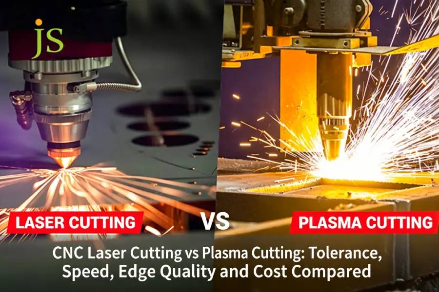

CNC laser cutting vs plasma cutting comes down to one variable: plate thickness. On sheet up to 12 mm, a fiber laser holds ±0.05 mm to ±0.10 mm, leaves a mirror-finished edge and cuts 2–3 times faster than plasma. From roughly 16 mm to 50 mm, that advantage reverses: plasma removes far more molten metal per second and costs less per machine hour, but it leaves a 0.80–2.50 mm heat-affected zone, 1°–3° of kerf taper and bottom dross that has to be ground off by hand.
Every number in this guide comes from JS Precision's own 2025 production data or from published ISO and ASTM standards, both cited inline.
CNC Laser Cutting vs Plasma Cutting Speed and Tolerance Comparison
|
Process Comparison Metric |
CNC Fiber Laser Cutting |
High-Definition Plasma Cutting |
Selection Benchmark (JS Precision Advice) |
|---|---|---|---|
|
Standard Machining Tolerance |
±0.05 mm to ±0.10 mm |
±0.50 mm to ±1.20 mm |
Laser for precision mating parts; plasma for welding/riveting |
|
Section Perpendicularity / Taper Angle |
0° to 0.5° (near vertical) |
1.0° to 3.5° (inverted trapezoid) |
Laser for strict vertical edges, avoiding milling |
|
HAZ Depth |
0.10 mm to 0.25 mm |
0.80 mm to 2.50 mm |
Prioritize nitrogen fiber laser to avoid bending micro-cracks |
|
Kerf Width |
0.15 mm to 0.35 mm |
1.50 mm to 3.80 mm |
Laser for tight nesting and fine holes |
|
Economical Thickness (Carbon Steel) |
0.5 mm to 16.0 mm (ultra-fast) |
12.0 mm to 50.0 mm+ (high penetration) |
Crossover zone 12–16 mm: decide by tolerance requirement, not thickness alone |
ISO 9013:2017defines geometrical product specifications and quality tolerances for classifying thermal cuts, and applies to laser cuts from 0.5 mm to 32 mm, plasma cuts from 0.5 mm to 150 mm, and flame cuts from 3 mm to 300 mm. It classifies perpendicularity and surface roughness into ranges — it does not prescribe which process to choose.
If the requirements of a project include dross-free edge tolerances on thin-to medium thickness plates (≤12 mm), fiber laser is the best option; if it's just the speed and large allowance blanking needed for thick structural steel ≥16 mm, plasma will be the more suitable technology.
Why Does Plate Thickness Dictate Cutting Speed in Laser Cutting vs Plasma Cutting?
Cutting speed dynamics in CNC laser cutting vs plasma cutting reverse around a 6 mm to 12 mm plate thickness transition threshold. Fiber lasers outpace plasma up to 3x on sheet metal below 6 mm by concentrating 12 kW into a spot a fraction of a millimetre wide, while plasma wins above 16 mm by removing a far larger volume of molten metal per second.
The energy transfer mechanism determines the velocity inflection point.
- A 12 kW fiber laser runs at about 40–45 m/min on 1 mm carbon steel, 20–25 m/min on 2 mm and 10–14 m/min on 3 mm.
- The limitation is geometric, not thermal: because the arc spreads as it travels down through the kerf, plasma produces a tapered edge. On thin sheet this taper is a problem; on thick structural plate it is usually within the drawing allowance.
- On sheet up to 6 mm, laser cutting is 2–3 times faster than plasma.
Why does plasma pull ahead on plate thicker than 16 mm?
- On 20 mm and 30 mm plate, the plasma arc holds a steady 1.2–1.8 m/min by penetration of the 20,000°C molten pool with the simultaneous high-momentum gas flow.
- Laser throughput collapses on thick plate because piercing takes seconds rather than milliseconds, and because beam absorption falls off inside a deep, narrow kerf.
- On carbon steel 16 mm and thicker, laser's speed advantage over plasma disappears entirely.
Material hardness as a constraint on removal rate
- Brinell hardness influences how quickly a tool can remove metal and how hard that tool must be — but note that thermal cutting is far less sensitive to hardness than milling or drilling.
- Once the hardened edge layer reaches 35–45 HRC (about 350–450 HV), standard CNC tooling chips or breaks.
- In a 2025 high-strength steel project, JS Precision switched a 20 mm carbon steel part from laser to plasma and cut cycle time per part by 65%. At 8 mm the gap narrows to 28%, as shown in the cost model below.
ASTM E10-23, Standard Test Method for Brinell Hardness of Metallic Materials, specifies the requirements for the testing machine and the procedure for performing Brinell hardness tests.
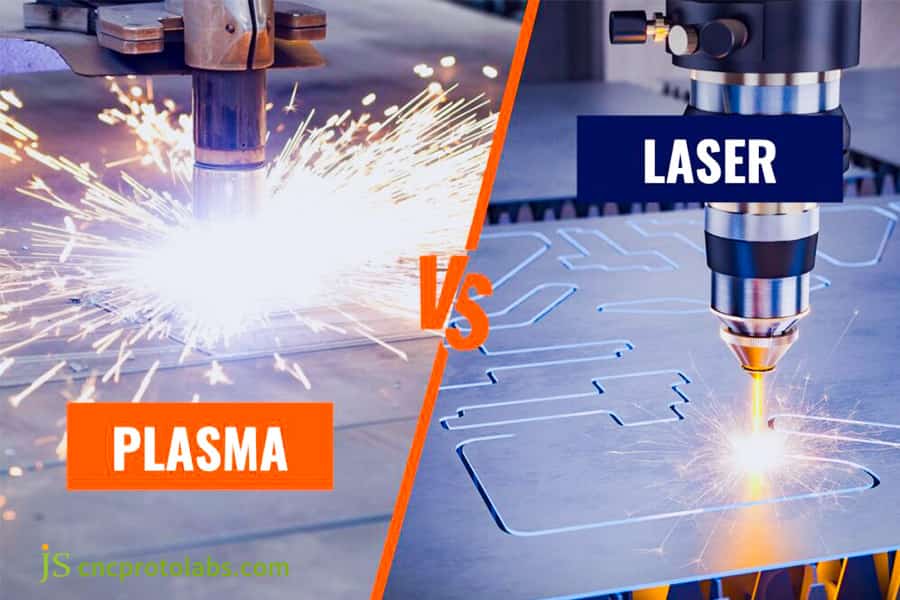
Figure 1: Laser vs plasma cutting metal sheet comparison.
How Do Edge Quality and Surface Roughness Differ Between These Two Cutting Methods?
Laser cutting edge quality yields a superior surface roughness of Ra 1.6–6.3 μm with virtually zero dross, whereas plasma leaves a roughness of Ra 12.5–25 μm, with top-edge rollover and bottom dross. A CNC laser cutting service achieves these weld-ready perpendicular faces by blowing molten material out of the kerf with a high-pressure gas jet before it can re-solidify.
Cross-sectional roughness and slag dynamics control
- Fiber lasers running nitrogen assist at 14–20 bar (1.4–2.0 MPa) produce oxide-free cut faces with end-face roughness as low as Ra 1.6–3.2 μm.
- The disturbance effect from the rotating plasma arc causes the cut to show visible periodic ripples and slag attached to the surface.
- The labour spent removing top-edge rollover and bottom burrs by hand often cancels out plasma's lower machine-hour rate.
ISO 17658 Terminology Comparison for Thermal Cutting Defects
|
Defect Category (per ISO 17658) |
Laser Cutting Manifestation |
Plasma Cutting Manifestation |
Severity Grade |
|---|---|---|---|
|
Dross Adhesion |
None to minimal |
Heavy bottom dross |
Plasma: Severe |
|
Edge Rollover |
≤ 0.05 mm |
0.30–0.80 mm |
Plasma: Marked |
|
Kerf Geometry Deviation |
< 0.05 mm |
0.50–1.20 mm |
Plasma: Significant |
|
Surface Roughness Rz |
10–30 μm |
250–500 μm |
Laser: Range 2–3; Plasma: Range 4–5 |
ISO 17658:2002 specifies terminology for imperfections in oxyfuel flame cuts, laser beam cuts and plasma cuts, providing the standardized defect classification framework for thermal cutting quality assessment.
Subsequent welding and spraying pretreatment requirements
- Laser cutting sections can be directly laser welded or sprayed without the need for polishing.
- The plasma-cut surface needs to be manually cleaned with an angle grinder, otherwise the coating adhesion will be affected.
- JS Precision's CNC laser cutting service uses high-pressure auxiliary gas to increase slag removal rate.
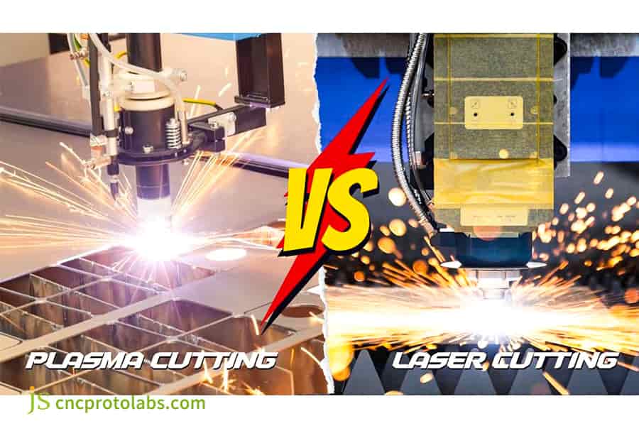
Figure 2: Plasma cutting vs laser cutting edge quality.
How Does the Heat-Affected Zone Impact Tolerances and Hardness in CNC Laser Cutting?
The heat-affected zone (HAZ) largely determines whether a part stays in tolerance. Laser holds distortion to about 0.1 mm, keeping cut dimensions within ±0.05 mm to ±0.10 mm. Plasma subjects the workpiece to a much wider thermal field — an 0.80–2.50 mm HAZ — which generates internal stress and hardens the cut edge to as much as 45 HRC.
Changes in heat-affected zone and microstructure
- The sudden rise in temperature and fast cooling that happens during plasma cutting produces a hard martensitic layer on the edge of high-strength steel with a microhardness suddenly rising to 350–450 HV.
- That layer chips drills and taps, and can crack along the HAZ fusion line duringcold bending.
- With a very short exposure time, the laser's heat-affected zone is only 0.10–0.25 mm, resulting in very little thermal distortion of the underlying metal.
Precision parts assembly tolerance drift analysis
- Laser cutting allows the tolerances of assembled precision parts to remain stable at ±0.05 mm.
- Since the thermal stress is released in plasma cutting, released thermal stress pushes flatness outside tolerance, so parts must be levelled after cutting.
- JS Precision uses pulse modulation to cut the laser HAZ to 0.10–0.25 mm, roughly one-tenth of a plasma cut.
The impact of a sudden increase in hardness on subsequent machining
- At 45 HRC the plasma-cut edge is above the comfortable range of standard HSS tooling (about 30 HRC), so drills and taps chip or break. Laser-cut edges stay near base-metal hardness and need no special tooling.
- After laser cutting, the hardness change in the heat-affected zone is slight so there's no need for special tooling.
- Based on JS Precision's practical experience in the 2025 mold steel project, the tool life was increased by 3 times after switching to laser technology.
Worried about thermal distortion on thin plate? Send us your drawing and we will quote the pulse parameters that keep HAZ under 0.25 mm.
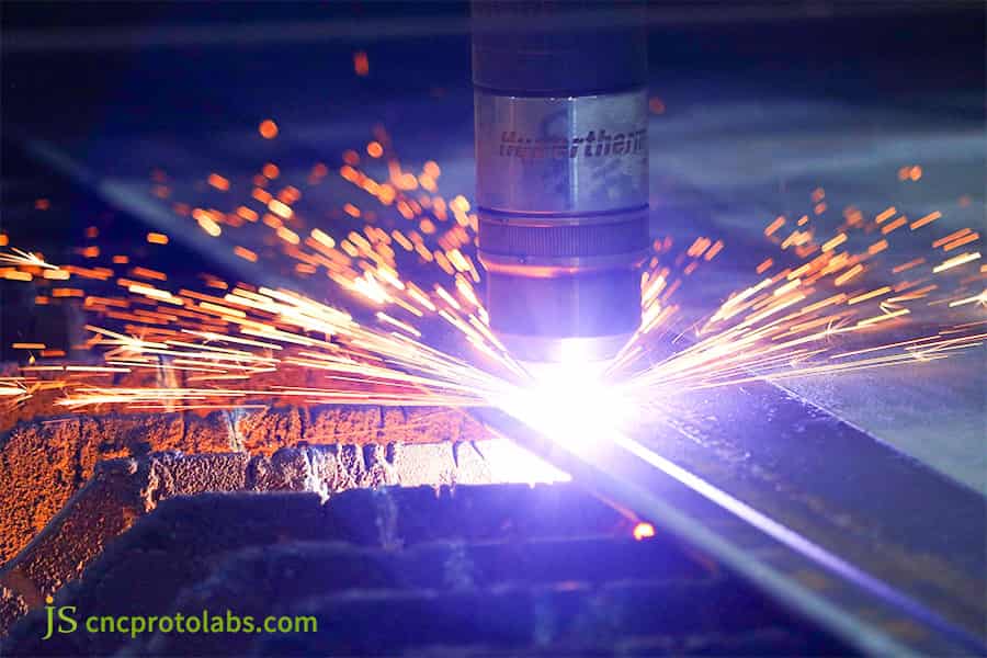
Figure 3: CNC laser cutting metal sheet with bright sparks.
Why Does Kerf Taper Create Assembly Bottlenecks for Plasma Cut Components?
Kerf taper determines assembly accuracy, as standard plasma cutting introduces an intrinsic 1° to 3° edge taper compared to the near-zero (<0.5°) taper of a custom laser cutting service. This angular variance restricts tight mechanical mating, forcing engineers to specify wider tolerances or add milling operations.
Plasma arc cone angle formation mechanism
- The plasma arc does not release energy evenly through the plate depth: it is widest at the top and narrows toward the bottom, which produces the characteristic 1°–3° cut cone.
- Any hole whose diameter is less than 1.5 times the plate thickness ends up flared at the mouth, and the pin will not seat.
- The conical expansion of the plasma jet is one of the characteristic features of plasma cutting that no combination of control parameters can fully eliminate.
Cases of failure in precision hole fit
- The 6 mm aluminum alloy battery tray bracket was initially produced through plasma machining but the mounting hole taper reached 2.8°, so the M8 bolts went in crooked and would not seat.
- With fiber laser and dynamic focus control, taper stays within 0°–0.5°, so the bolts seat without forcing.
- JS Precision's custom laser cutting service completely solved this bottleneck.
Laser dynamic focus tuning technology
- Dynamic focus control places the beam waist at mid-plate thickness, holding the cut angle to 0.5° or less.
- Negative focus compensation focuses the energy at the bottom of the plate, so slag cannot re-solidify on the lower edge.
- The use of this technology allows the laser cutting tolerance to be locked at ±0.06 mm, so that all deburring processes can be skipped.
Losing parts to hole taper? Ask for our K-factor and springback compensation database — it ships free with every quote.
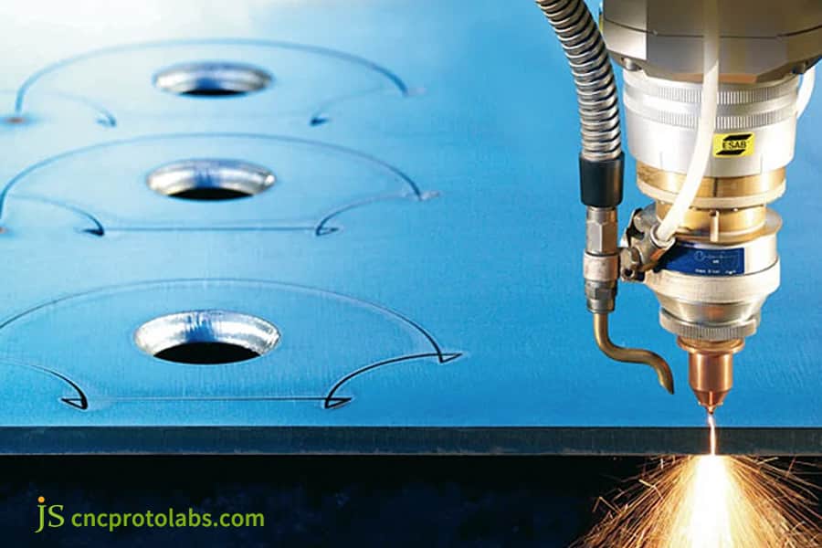
Figure 4: Laser cutting precision holes on blue metal.
Why Is a Dedicated Laser Cutting Service for Sheet Metal Essential for High-Mix Production?
Utilizing an advanced laser cutting service for sheet metal is critical for complex geometries because optical precision allows kerf widths as narrow as 0.2 mm and nesting clearances under 2 mm. Plasma cannot match that resolution: the arc column is inherently wide and displaces molten metal violently.
Nesting efficiency and raw material cost
- With a 0.2-mm kerf width, fiber lasers bring the distance between components down to 1.5 to 2 mm and the total material utilization rate stays at 88 to 93%.
- Plasma needs a lead-in path and a 6–10 mm web between parts, which pushes material utilisation well below the laser's 88–93%.
- By using a shared-line cutting algorithm, JS Precision's CNC laser cutting service is able to efficiently use the material and cuts scrap.
Microsecond piercing control and shared-line cutting
- The microsecond-level pulse rapid perforation algorithm decreases the idle time and enhances the productivity.
- The common-line cutting lets two adjacent parts share a single cut path, halving both cycle time and heat input.
These technologies maximize the cost-effectiveness of laser cutting service for sheet metal.
Machining of complex small contours and dense holes
- The narrow laser kerf is the practical way to produce dense louvre arrays and irregular chamfers.
- Plasma cannot hold small features because the arc column itself is 1.5–3.8 mm wide and the surrounding heat distorts anything finer.
Running high-mix, low-volume? Our shared-line nesting typically lifts material utilisation from 78% to 88–93%. Send a STEP file and we will show the nesting layout.
Which Cutting Process Delivers Lower Total Manufacturing Costs Beyond Machine Run-Time?
Evaluating overall manufacturing costs reveals that a CNC laser cutting service frequently costs less per finished part on sheets up to 12 mm by eliminating secondary slag grinding and edge milling. Plasma cutting appears cheaper in hourly machine rates but incurs heavy post-processing labor on complex profiles.
Total Cost Accounting (TCA) model
|
Cost Component |
Fiber Laser (8mm CS) |
HD Plasma (8mm CS) |
Difference |
|---|---|---|---|
|
Cutting Time (min/pc) |
2.5 |
1.8 |
-28% |
|
Assist Gas Cost ($) |
1.20 |
0.30 |
-75% |
|
Deburring Labor (min) |
1 |
5.0 |
+100% |
|
Rework/Scrap Rate (%) |
0.5 |
3.5 |
+600% |
|
Total Cost per Part ($) |
8.50 |
10.20 |
+20% |
Source: JS Precision internal production data, 2025 (8 mm S275 carbon steel, 500-piece batch).
Manual polishing time and hidden expenses
- Every plasma-cut 8 mm carbon steel part needs another 3–5 minutes of hand grinding which in total extends the cutting process time by 40%.
- Hand grinding also risks taking local dimensions out of tolerance, which is why the delivered cost of a plasma part runs 15–20% above the laser part.
- High-pressure nitrogen purging in JS Precision's laser cutting machine produces slag-free edges, which removes the grinding operation from the process route.
Scrap Rate and Rework Cost Analysis
- Plasma's thermal input also causes flatness deviation, and the levelling and rework needed to correct it adds further cost.
- Laser cutting has an extremely limited heat-affected area with a scrap rate under 0.5%.
Upload your .DXF or .STEP file with material, quantity and tolerance. A senior engineer returns a DFM review and itemised quote within 12 hours.
How JS Precision Eliminated Secondary Grinding and Tightened Tolerances on Battery Tray Brackets?
The customer's problem
- A European commercial-vehicle OEM was producing a 6 mm 6061-T6 aluminum battery tray bracket on high-definition plasma.
- Taper of mounting hole is 2.8°, and the M8 fastening bolt is misaligned and cannot be seated.
- Hard oxide residue on the lower edge kept three full-time workers busy with angle grinders. Output stalled at 800 sets a month against a higher line demand, and the assembly line was at risk of stopping.
JS Precision Solution
- We ran the bracket on a 15 kW fiber laser with 18 bar (1.8 MPa) nitrogen assist at 99.999% purity.
- A negative focus offset of −1.5 mm puts peak energy at the lower surface, so molten material is expelled before it can re-solidify as a secondary layer.
- Two-stage piercing cut spatter from the 8.5 mm locating hole by 95% and stopped back-spatter from reaching the protective lens.
- The sheet material expansion due to thermal effects results in micron-level deviations, which can be rectified automatically by the CCD machine vision contour edge-finding algorithm.
Failure experience and lessons learned
- In the first 50 pieces, a 1.5 mm dual-flow nozzle produced turbulent gas flow at the edge of the molten aluminum pool and left micro-burrs at the corners.
- The team switched to a 2.0 mm single-piece Laval copper nozzle with anti-back-flash geometry and raised nitrogen pressure by 0.2 bar, which eliminated corner slag completely.
Final result
- The perpendicularity error of the cut surface was reduced by 92.8% as it went down from 2.8° to within 0.2°; hole center tolerance was always ±0.06 mm.
- With deburring and polishing removed, total processing cost per unit fell 34%, and the production and delivery cycle dropped 64%, from 14 days to 5.
- The first batch of 5,000 pieces passed inspection in full and has shipped.
Data source: JS Precision Internal Engineering Report Project QA Report: Battery Tray Bracket Batch #2025-BTB-04.
Have a bracket or tray with the same taper problem? Send the drawing — we will return a DFM report and a tiered quote (prototype / 100 pcs / 1,000 pcs) within 12 hours.
FAQs
Q1: What is the main speed difference in laser cutting vs plasma cutting speed?
Generally speaking, the sheet material's thickness governs the speed change. On sheet thinner than 6 mm, a fiber laser runs at roughly 25–45 m/min — about 2–3 times faster than plasma. Thick steel sheets over 16 mm plasma can be cut at a steady-state speed of 1.2–1.8 m/min. Laser cutting speed loses its advantage if hole-making delay takes too long.
Q2: Can plasma cutting achieve the same laser cutting tolerance on precision parts?
You can't get the level of precision from plasma as laser. The cut thickness of the metal is 0.2 mm by the fiber laser with the accuracy of ±0.05 to ±0.10 mm. The plasma cutting accuracy tolerance is between ±0.50 and ±1.20 mm and it is only used for very heavy steel structures or further milling of blanks after laser cutting.
Q3: How does edge dross affect total costs in laser cutting service for sheet metal?
Residual buildup causes hidden labor cost increase. By using high pressure laser nitrogen purge the slag can be cleaned away without the need to manually grind the inside surfaces; plasma treatment leaves oxide deposits on the bottom and angle grinders are used to manually scrap the pieces off, adding between 15%–20% per unit.
Q4: What is the heat-affected zone difference between laser and plasma cutting?
Laser HAZ is only 0.10–0.25 mm, with extremely low thermal deformation; plasma HAZ reaches 0.8–2.5 mm, and rapid cooling causes the carbon steel edge to harden to 45 HRC, which exacerbates tool chipping and causes bending microcracks.
Q5: When should an engineer choose plasma cutting over laser cutting?
For cutting large carbon steel machine bases, bridges, and ships with a thickness of ≥16 mm, plasma cutting is more economical. These workpieces have no strict limitations on taper or surface roughness, and plasma cutting consumables are inexpensive, offering a cost advantage in terms of cutting speed.
Q6: Why does JS Precision use fiber lasers instead of CO2 lasers for sheet metal cutting?
JS Precision runs 1.07 μm fiber lasers, which absorb far better in reflective metals such as aluminum and copper alloys and are about three times more energy-efficient than CO2 sources. It is also equipped with a smart focusing head and the perpendicularity of an end face is maintained within 0.5° with tolerances of 0.05 mm.
Q7: How do you request an instant quote for custom laser cutting services?
Upload CAD vector graphics (.DXF/.DWG/.STEP) indicating material, quality, and tolerances. An engineering department will check the DFM and reply with a detailed quote in 12–24 hours, relying on the factors like nesting rate, cutting length, number of perforations, and type of auxiliary gas.
Q8: Can CNC laser cutting eliminate subsequent CNC milling operations?
For most 2D parts from thin and medium plate, laser cutting replaces vertical milling: the edge comes off at Ra 3.2 μm or better with perpendicularity inside 0.3°, so no further machining is needed.
Summary
The choice between laser and plasma depends on the sheet thickness, perpendicularity, tolerances, and grinding time. Plasma offers a low-cost advantage for blanking carbon steel with a wall thickness of ≥16 mm; while in the field of sheet metal parts with a thickness of 0.5–12 mm, CNC fiber laser, with its ±0.05 mm tolerance, zero slag buildup, and extremely low thermal deformation, can eliminate the need for subsequent edge grinding, reducing procurement costs across the entire process.
If your product assembly has stringent requirements for edge perpendicularity, precision fastening hole fit, and appearance quality, JS Precision offers complete manufacturing support. Our factory is equipped with a 15 kW high-power fiber laser machine and fully automated CNC bending and machining lines, supporting rapid, precise prototyping and mass production of stainless steel, aluminum alloys, brass, and high-strength structural steel. Send your CAD drawings (.DXF / .STEP) to the JS Precision technical support team immediately, and our engineers will provide you with a DFM review and an accurate production quote within 12 hours (complex assemblies: 24 hours).

Disclaimer
The contents of this page are for informational purposes only. For JS Precision Services, there are no representations or warranties, express or implied, as to the accuracy, completeness, or validity of the information. It is the buyer's responsibility to identify specific technical requirements and request a formal parts quotation. Please contact us for more information.
Resource

