 English



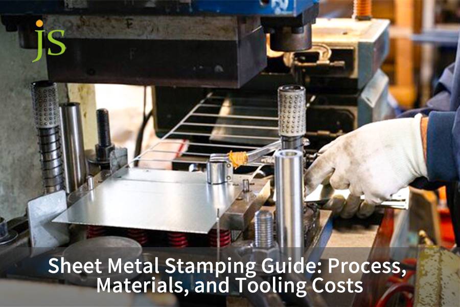

Sheet metal stamping uses cold forming techniques to convert coils of flat sheet metal into highly accurate component parts either through blanking punching bending or deep drawing processes. This cold-forming technology is instrumental in mass production because it achieves tolerances down to ±0.02 mm at high cycling speeds (30–500 SPM), and it helps bring new concepts to commercial scale.
Core Answer Summary Table
For metal stamping, once production surpasses the break-even point, batch sizes of about 5,000–10,000 pieces become economical when progressive dies are used. In the meantime, tolerances can be held within ±0.02 mm and the per-piece cycle time cut to under 1 second.
|
Evaluation Dimension |
Key Engineering Parameters / Industry Benchmarks |
Selection Rule / Decision Criteria |
|---|---|---|
|
Standard Tolerances |
±0.02mm to ±0.05mm (DIN 6930-2 precision class) |
Electronic connectors → progressive die; large deep-drawn enclosures → transfer die |
|
Economic Break-Even Volume |
5,000–10,000 pcs (vs. CNC/laser cutting) |
<1,000 pcs → laser bending; >5,000 pcs → open progressive die |
|
Tooling Cost & Lead Time |
$3,000–$35,000+; lead time 3–6 weeks (incl. T1 sample) |
Pilot run → soft tool; million-stroke production → DC53 progressive die |
|
Compatible Material Grades |
SPCC, SUS304, Al5052-H32, C2600 brass |
Deep drawing → SPCE; corrosion resistance → 304; lightweight → 5052 |
|
Tonnage Calculation |
P = L × t × τ (perimeter × thickness × shear strength) |
Machine rated tonnage must reserve 25%–30% safety margin |
Sources: Tolerance per DIN 6930-2: 2011; cost and lead time per JS Precision internal data (2025–2026); tonnage factor per industry practice with 25%–30% margin.
Want to assess whether your parts are suitable for stamping? Contact JS Precision, and our engineering team will provide you with a free DFM analysis and preliminary quote within 24 hours to help you make a quick decision.
What Is the Sheet Metal Stamping Process, and How Does It Scale for Mass Production?
The sheet metal stamping process is a cold-forming method where high-tonnage mechanical or servo presses force coiled strip into tool steel dies. By consolidating blanking, piercing, forming, and coining into continuous cycles operating at 30-500 SPM, it produces components with tolerances down to ±0.02 mm. Stamping dominates high-volume manufacturing because initial tooling expenses amortize over large production runs, reducing piece-part manufacturing costs to near raw material market value.
Stamping dynamics: Selection between mechanical and servo presses
The choice of driving force directly affects product quality and production efficiency. For beginners, a detailed sheet metal stamping guide can help understand the basic principles of different types of punching machines.
- Mechanical punch press (crank mechanism): it uses flywheel energy storage, has a fixed punch length and high stroke, it is suitable for simple high-speed punching and shallow drawing. The problem is that, the holding time at bottom dead center is short. Because of this, it is hard for springback of complex shapes to be controlled.
- Servo punch press: It is driven by servo motor with bottom dead center pressure holding, stroke curve programming and stepless speed adjusting, which can accurately control the flow of material and reduce springback and is suitable for high-strength steel and deep-drawing parts.
- Selection criteria: For accuracy of ±0.05 mm or better, mechanical punching is sufficient. Parts requiring stringent springback control or complex forming call for a servo press. Servo punch press would be a better choice.
The technical roots of mold price fluctuations: from materials to stiffness
The significant differences in mold pricing stem from several key technical factors.
- Coil thickness tolerance (Δt): The thickness of the coils supplied by steel suppliers is not a fixed value, for instance SPCC cold rolled sheet has a tolerance of ±0.05mm which is translated directly to the stamped parts to influence the bending angle and fit clearance. The lower this tolerance, the more expensive the material and the more difficult mold adjustment becomes.
- Seal mold frame differs in stiffness: the cast-iron mold base (HT300) absorbs vibration well, but its stiffness and fatigue strength are inferior to those of a 45# steel frame; a heat-treated 45# steel frame withstands larger eccentric loads and holds accuracy at high speed—at higher cost.
- Effect of stamping springback: The change of the thickness of the material and the elastic deformation of the die set can mean the actual forming force different from the theoretically calculated force, also lead to the springback unpredictably. For controlling the springback and make good quality parts, high-rigidity die set and tight tolerances for the materials are necessary.
Strip layout: The first hurdle to reducing costs
The sheet design has a decisive influence on the usage of raw material and is at the same time the most direct connection to control stamping costs. Within the whole process of sheet metal stamping,
- Standard utilization rate: when optimizing the arrangement of parts on strip (single row, double row, staggered row) in progressive die designing, the standard utilization rate can be kept in 75%-88%.
- Factors affecting utilization rate: Geometric shape of the part, value of overlap (width of the carrier), pitch of feed. Small utilization rates are common to have on complicated and irregular parts.
- Combine various designed parts through the adoption of zero waste layout or low waste layout or compose different parts on the same strip stamping through nesting technology can much improve the material utilization and reduce the unit cost.
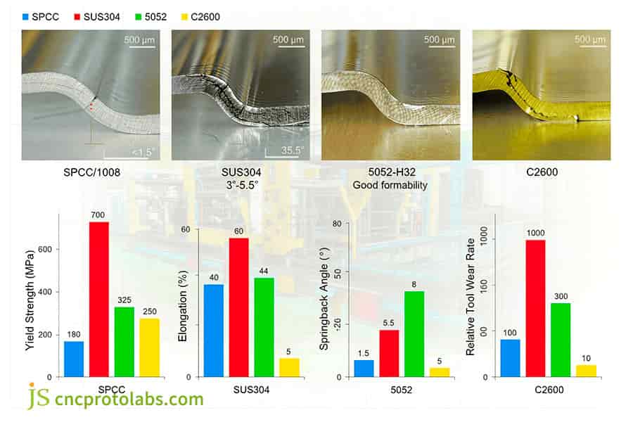
Figure 1: Diagram of sheet metal stamping press mechanism showing die set and components.

How Does Progressive Die Stamping Work Compared to Transfer and Stage Tooling?
Progressive die stamping feeds continuous coil stock through a sequential series of stations that incrementally cut, pierce, bend, and coin parts before final cutoff. In contrast to single-stage or transfer tooling that handles individual blanks, progressive dies run at 80-300 SPM, achieving positional tolerances within ±0.03 mm. Tool life routinely exceeds 1,000,000 strokes when configured with D2 or tungsten carbide inserts, minimizing labor-intensive secondary operations.
Differences in feed rate of three types of molds
Various types of mold are suitable for many production requirements and component features. The fundamentals of progressive die stamping must be understood before selecting the optimum mold.
Stage Tooling:
- Working principle: Only one of these operation (blanking punching bending etc.) is carried out at one stamping cycle.
- Features: Easy structure, low die cost(as low as around $2,500) though multi presses or multi stations are needed, this way low efficiency and high cumulative positional errors.
- Applicable Jobs: Small batch trial production and parts with extremely simple shapes (less than 5000 pcs).
Transfer Tooling:
- Working principle: robotic arm moves individual sheet metal blanks to and from separate tooling stations for multiple operations.
- Application: large parts (like automotive door panels) or parts that involve deep drawing. The tooling is quite flexible but the robotic arm system is complex and its speed is slower than progressive dies (around 15-40 SPM).
- Applications areas: Production of "large and "complex shapes" parts by deep drawing.
Progressive Die:
- Working principle: The rolled material was supplied into the die by a feeder. Inside a single die, a number of operations—such as punching, bending, and stretching—are performed. The final item is then cut away from the strip, which is known as separation.
- Characteristics: very high production efficiency (80-300 SPM), good positional accuracy (±0.03mm), low semi-finished product turnover. Yet the die structure is complicated and cost is very high (5,000−35,000+).
- Where can this be used: good for mass production (>10,000 pieces) of small to medium precision components (like electronic switch connectors terminals springs etc.)
Blanking clearance calculation: the golden rule that determines cross-sectional quality
The punching clearance is the gap on one side between the punch and die, it has a great influence on the cross-section quality, die life and punching force. The correct standards of the progressive die clearance may improve the cross-section quality effectively.
- Calculation: usually, blanking clearance is proportional to the sheet thickness t, C= (blanking clearance) =k t where k is a coefficient. For a normal cold-rolled steel, recommended value of is often 5%-12% t. For 1.0mm thickness SPCC steel sheet, the clearance on one side would be the blanking clearance 0.05mm.
- Impacts of oversize clearance: decreases of bright band on the cross-section, increase of fracture band, the height of burr is higher than 10% t, and decreases of accuracy parts.
- Results of too little clearance: second shearing, second bright band, increased punching force and die wear, and possible die chipping.
- Better solution: find the ideal value of clearance value following professional standards (see DIN 9866 for an example) or using finite element analysis(FEA) for some kind of material and its thickness.
Mold material configuration: from standard parts to high-performance coatings
Choosing the right mold material and surface treatment is key to extending mold life and ensuring product quality.
- Standard parts selection: Under normal working conditions, SKD11 or D2 mold steel is usually used as the working parts of the mould. The hardness can be increased to 58-60 HRC after heat treatment, with good toughness and wear resistance;
- High-wear stations: stations that punch thick plates or stainless steel need higher-grade materials such as DC53 (high wear resistance and toughness) or cemented carbide (WC-Co, very high wear resistance but very low toughness) as the tips.
- PVD titanium coating: it brings a PVD coating (TiAlN, CrN etc) to the mold surface which can lower the coefficient of friction, enhance surface hardness, offers anti-adhesion and anti-scratch features. It's used under the situation of stamp on stainless steel and aluminum alloy.
How Does Sheet Metal Stamping Material Selection Affect Formability and Tool Wear?
Sheet metal stamping material selection dictates forming limits, required tonnage, and die degradation rates through physical properties like yield strength, elongation (A80), and work-hardening exponent (n-value). High-ductility alloys such as SPCE deep-drawing steel (>35% elongation) facilitate complex draws without tearing. Conversely, high-strength materials accelerate tool friction and amplify angular springback (2°-7°), requiring predictive finite element compensation (FEA) and specialized die steel metallurgy.
Key forming parameters: Deciphering the forming code of materials
Having a clear conception of 4 design parameters before the correct choice of material can be made. For the complete procedure of sheet metal stamping material selection, a careful consideration of these indicators is equally important.
- Yield strength(Rp): The stress corresponding to the initiation of plastic deformation. The larger yield strength, the larger forming force applies and the worse springback occurs.
- Tensile strength (Rm): The maximum stress of a material before failure, which influences the punching force and the stress limitation of the die.
- Plastic strain ratio (r-value): an index of a material's resistance to thinning during drawing. The larger the value is, the higher toughness of material.
- Work hardening index (n-value): Represents the rate of increase in strength of the material with deformation. The greater the n-value, the greater the uniform deformation. Conversely, the increased n-value also increases mold wear.
Forming performance and selection criteria for four types of substrates
|
Material |
Yield Strength (MPa) |
Tensile Strength (MPa) |
Elongation A80 (%) |
n-value |
Springback Angle |
Key Application Notes |
|---|---|---|---|---|---|---|
|
SPCC / 1008 Cold Rolled Steel |
140 - 280 |
270 - 410 |
> 35 |
~0.20 |
< 1.5° |
Excellent formability, low cost, suitable for general stamping. |
|
SUS304 Austenitic Stainless Steel |
205 - 310 |
520 - 720 |
> 40 |
~0.45 |
3° - 7° |
Rapid work-hardening, high tonnage needed, prone to galling. |
|
5052-H32 Aluminum Alloy |
130 - 230 |
210 - 290 |
12 - 22 |
~0.16 |
< 2° |
Good corrosion resistance, moderate formability, suitable for bending. |
|
C2600 Cartridge Brass |
110 - 220 |
330 - 480 |
> 46 |
~0.35 |
< 1° |
Excellent ductility, good electrical conductivity, but prone to edge burrs. |
Sources: ASTM A1008/A1008M-21 Standard Specification for Steel, Sheet, Cold-Rolled, Carbon, Structural, High-Strength Low-Alloy, and High-Strength Low-Alloy with Improved Formability; ASM International Metals Handbook, Vol. 2.
Rebound Compensation: From Experience to Science
Springback is an unavoidable occurrence during metal stamping in particular for high-strength steel and stainless steel. Reliable sheet metal material properties data are the foundation for springback compensation.
- Springback mechanism: the releasing of residual stress occurs after a bend, the shaped features of the part change from the shape of the mold to the slight difference.
- Conventional compensation: 'Over-bending' is the die angle is intentionally increased beyond the target product angle based on experience. Over-bending compensations for low carbon steel are of 0.5°-1.5° and for SUS304 stainless steel are of 3.0°-5.5°.
- Feeding method: Using finite element analysis (FEA) software to perform precise numerical simulation mostly forming process; Using FEA to simulate the forming process, the springback amount is predicted accurately and corrected at the die-design stage, which significantly shortens the trial-production cycle and improves first-time yield.
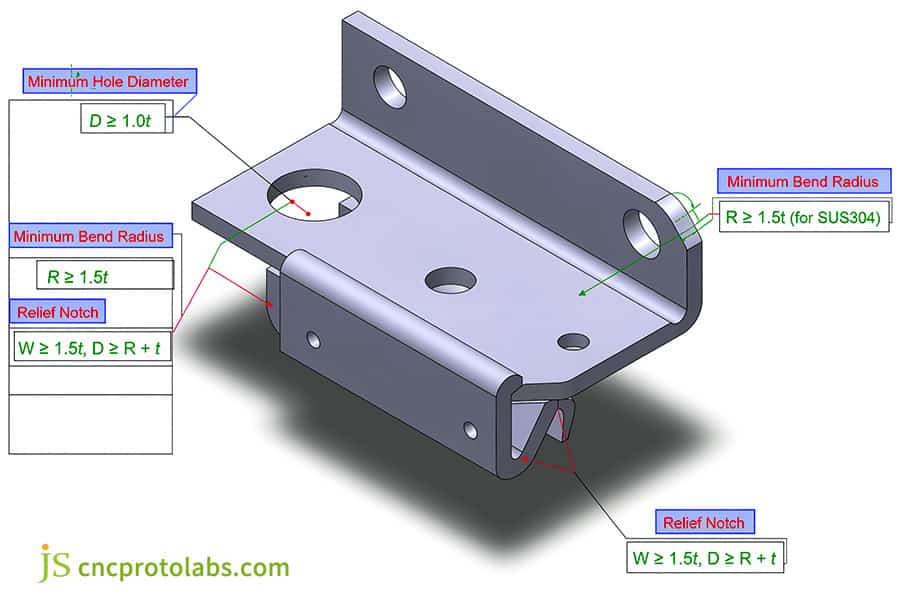
Figure 2: Chart analyzing stamping materials formability, yield strength, and tool wear rate.
Carbon Steel vs Stainless Steel Stamping: What Are the Key Engineering Differences?
In carbon steel vs stainless steel stamping, mechanical and wear behaviors diverge sharply due to stainless steel's rapid work-hardening rate (n-value ~0.45 vs ~0.20). Stainless steel (SUS304) demands 40%-60% higher tonnage, tight clearance control (8%-10% t), and PVD-coated carbide dies to prevent severe galling. Carbon steel (SPCC/1010) offers superior drawability, minimal springback (<1.5°), and 3x longer punch lifespans before regrinding, significantly reducing maintenance overhead.
Strain hardening mechanism and edge quality
A big difference can be seen between carbon steel and stainless during stamping. Knowing what to compare in the carbon steel vs. stainless steel stamping comparison will aid in choosing the proper process parameters.
- Martensitic transformation: strain-induced martensitic transformation occurs on deforming austenitic stainless steel (like SUS304) at room temperature. A large amount of the austenite is transformed to martensite. This process raises the steel's strength and hardness substantially, but at the expense of brittleness.
- Larger fracture zone at cut edge stainless steel is mechanically work-hardening than carbon steel in a very high rate. The fracture zone in stainless steel is wider and the cross-section quality is lower than in carbon steel in the punching processes. To produce a good cross section, smaller punching clearance, (8%-10% t ) and sharp die edge are needed.
- Countermeasures: install the PVD-coated mold to lower friction, or optimize the lubricant formula, or provide the shaving process into the shape of mold to get rid of rough fracture zone.
Mold Wear Comparison: A Trade-off Between Lifespan and Cost
Drawing from practical experience of precision terminal stamping by JS precision, material effect on die life is a key thing in choosing process route, and when dealing with the difficulty of deep drawing with stainless steel, increasing the die material becomes critically important.
- Stamping SPCC carbon steel: The punch is made of D2 die steel, whose grinding cycle is about 150,000 - 250,000 strokes, and can operate stably for some weeks before being repaired.
- Stamping any SUS304 stainless steel: using the same D2 punch, the regrind interval drops to only 30,000–50,000 strokes due to high hardness and high work hardening rate of stainless steel which causes rapid die wear.
- Solution: use a better material for the STS die making. Using DC53 or powder high speed steel (e.g. ASP23) with PVD coating can bring the punch life back to above 100,000 strokes and the die cost will be 30%–50% higher.
Springback Angle Compensation Difference: A Key Design Parameter
During the bending process, the springback behavior of the two materials differs greatly, and precise compensation must be made in the mold design.
- Low carbon steel (SPCC): Lower yield strength and lower modulus of elasticity, which means less springback. When designing benddies, only 0.5°-1.5° overbending compensation should be used.
- SUS304-Typical stainlesssteel: high yield and fast work hardening causes heavy springback, design may have to be for 85°, or even less to produce 90°, corresponding to 3.0°-5.5° over-bending compensation.
- Mathematical importance: neglecting this difference will result in parts out of tolerance in the angles and an unsuccessful assembly. As a result, it is required for the exact estimation of spring back amount, either through FEA simulation or empirical formulas then on to take into account in the mold design system in the initial phase of mold design.
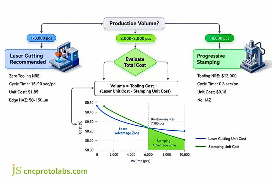
Figure 3: 3D model of stamped bracket showing DFM guidelines for minimum bend radius.
Metal Stamping vs Laser Cutting: What Is the Cost Break-Even Volume?
The economic division in metal stamping vs laser cutting hinges on production volume versus tooling amortization. Laser cutting requires zero tooling investment ($0 NRE) and fast setup, dominating low runs from 1 to 3,000 parts. However, progressive metal stamping slashes cycle times from 45 seconds to 0.3 seconds per piece. For production volumes exceeding 5,000-8,000 units, stamping's ultra-low per-unit processing cost fully amortizes the die tooling expenses, generating substantial compound savings.
Processing Cycle Time and Cost Structure: The Efficiency Gap
These two processes have entirely different costs structures that define each process' economic range of production. When the comparison is made between metal stamping process and laser cutting, the most obvious difference between the two processes is in the cycle time.
- Laser cutting: No mold cost (NRE=0), but high processing time for each part.For a part requiring an average complexity, it takes between 15 and 90 seconds with a fiber laser cutting, the charge being mainly the depreciation, the gas with the processing time.
- Progressive stamping: Heavy initial investment for molds (5,000-35,000) but very short process time per part, cycle time being only 0.2-1.5 seconds. Cost mainly depends on the amortization of the mold and the material used.
Cost Break-Even Point Calculation: A Real-World Case
Let's calculate the cost break-even point using a specific example. This metal stamping cost comparison clearly reveals the decisive impact of batch size on total cost.
Case parameters:
- Laser cutting fee per piece: $1.85
- Progressive die cost: $12,000
- Stamping unit processing fee (including materials): $0.18
Balanced batch point calculation:
Volume = Mold cost ÷ (Laser unit price − Stamping unit price) = $12,000 ÷ ($1.85 − $0.18) ≈ 7,185 pieces
This means that when the order quantity exceeds 7,185 pieces, the total cost of stamping will be lower than that of laser cutting. Thereafter, stamping saves $1.67 per additional piece produced. For an order of 100,000 pieces, stamping will saving more than $150,000 versus laser cutting.
Edge morphology differences: functionality and aesthetics
Beyond cost, there are also differences due to the edge conditions on the two processes which influence subsequent processes and performance.
- Laser-cut edges: A heat-affected zone (HAZ) of 50–150 µm is created. This changes the microstructure and hardness of the material. For components that will be welded, or subjected to dynamic loading, the HAZ may become the weak point leading to failure. In addition the edges contain slag and need to be ground, a second operation.
- Stamping edge: includes a bright band, a fracture band and micro burr. The bright band has excellent flatness, which makes it desirable mating surface. Despite the burr, its height can be controlled within 0.03 mm by controlling die clearance and machining in time, so it often does not require secondary trimming.
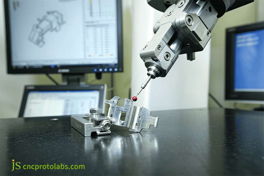
Figure 4: Flowchart and cost chart comparing progressive stamping and laser cutting volume.
What Are the Key Stamping DFM Guidelines for Minimum Bend Radius and Sheet Thickness?
What is the minimum bend radius and thickness for sheet metal stamping? Minimum sheet thickness typically ranges from 0.1 mm for precision micro-stamping to 6.0 mm for structural brackets. The internal bend radius (R) should never fall below 1.0X t for ductile metals (SPCC/5052) or 1.5x-2.0xt for high-strength steel and SUS304 to prevent tensile outer-fiber micro-cracking and excessive punch wear.
Minimum hole diameter and hole edge distance for punching: to avoid "bulging" and deformation.
Incorrect punching design may cause a deformation of the material surrounding the hole which distort the dimensions of the part. When answer question like ' What is the minimum bend radius and thickness for sheet metal stamping? ' we also need to take consideration of the punching process.
- Minimum diameter of punch: To maintain the strength of the punch, punch diameter D is not allowed to be too small. For ordinary steel, say SPCC, D ≥ 1.0 t. For SUS304 (a grade of stainless steel), considering the high strength, D ≥ 1.2 t.
- Minimum hole edge distance: distance L from the center of the hole to the edge of the part shall be sufficiently large to avoid edge material squeezing out during punching. Usually, the minimum hole edge distance shall be L ≥ 2.0 t.
- Hole spacing: The hole spacing (hole edge-to-edge) between two contiguous holes is normally greater than 2.0 t to prevent excessive deformation of material between the two holes while punching.
Bending pressure relief groove design: prevents corner tearing
If the area near the edge of a bent component is not designed properly, it can cause a huge stress concentration at the corner, leading to tearing.
- Problem: When the bending line intersects with the edge of the part, the material is stretched during the bending process, and there is no material to flow at the edge, which makes it very easy for cracks to occur.
- Solution: Design a relief cut at the end of the bend line.
- Slot width (W): at least 1.5 times the plate thickness, i.e. W ≥ 1.5 xt.
- Groove depth (D): at least equal to the inner radius of the bend R plus the plate thickness t, i.e., D ≥ R + t.
- Design principle: Ensure that the root of the pressure relief groove is rounded rather than sharp, in order to further disperse stress.
Mold cost reduction design: simplified structure and unified direction
Die costs are one of the major costs in stamping projects, for these costs can be quite a bit saved by minimizing part design changes. Using the bend radius and K-factor rule of thumb will minimize rework during the initial design stage.
- Standardise bending direction: when designing parts, standardise all bending direction to prevent complex use of lateral sliders(Cam Slides). Simplify the structure of mold, and decrease the cost and failure rate.
- Getting rid of lateral motion: the lateral slider system will complicate the mold and make it more difficult to maintain. When feasible, eliminate the slider motion by modifying the design of the piece (e.g. Replacing lateral holes with vertical punches).
- Use standardized design: every design mold parts (mold base guides punches) must be intended to avoid customized designed for decreasing mold manufacturing cycle and cost.
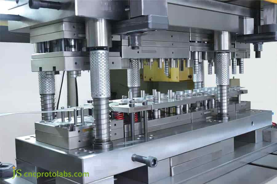
Figure 5: CMM machine inspecting precision stamped metal bracket part in factory.
How Much Does Metal Stamping Tooling Cost, and How Is Press Tonnage Calculated?
Metal stamping tooling cost varies widely based on part complexity and production volume. Progressive stamping dies range from $5,000 for small 4-station tools up to $35,000+. For complex multi-action automotive tooling, with typical lead times spanning 4 to 7 weeks including T1 pilot sampling. Tonnage requirements are calculated using P = L × t × τ (thickness × shear strength), adding a 25% safety buffer to prevent press stalling and die fracture.
Tooling NRE (Non-Recurring Engineering) Breakdown
Having knowledge where to mold costs contributes for techniques and suitable cost talks with suppliers. An analysis of cost of metal stamping tools can help the purchasing roles to prepare correct budgets.
- Mold base and guide pillars/sleeves (standard pieces): comprise 20%-25% of the total, and have relatively significant fixed costs, shaped by mold size, and precision requirements.
- Cutting edge and mold core forming parts: accounting for 15%-20%, are key to the cost variability rate, depends on the mold steel grades used (D2 DC53 cemented carbide).
- Wire EDM and CNC machining: representing 35%-45% of the total cost, it is the biggest cost item of mold manufacturing. It is closely related to the complexity of the mold, precision and machining time.
- Fitter assembly, grinding, and trial molding (T1–T3): 15%–20% of total cost. This stage is essential to the mold's dimensional life and fastening reliability; a more experienced fitter yields a faster cycle and higher quality. The more experienced the fitter, the faster the cycle, and the higher the quality.
Calculation logic and safety factor for total stamping tonnage
Accurately calculating the required press tonnage is a prerequisite for avoiding press overload damage and die breakage. Regarding the question, "How much does progressive die tooling cost, and what is the typical lead time?", tonnage calculation directly impacts the scale and cost of die design.
- Shear force formula for punching: F = L × t × τ
- F: Cutting force (unit: Newtons N)
- L: Perimeter of the blanking profile (unit: millimeters mm)
- t: Sheet thickness (unit: millimeters mm)
- τ: Shear strength of the material (unit: megapascals, MPa), usually 0.8 times the tensile strength.
- Total Tonnage Setting: After calculating the theoretical punching force, the unloading force, ejection force, clamping force, and possible off-center loads must also be considered. Total tonnage = F × 1.3 (safety factor). A safety margin of 25%-30% prevents instantaneous overloads caused by material thickness fluctuations, die dulling, etc.
Mold grinding and maintenance cycle: the lifeline for maintaining precision
|
Mold Type |
Expected Life (Strokes) |
Material |
Typical Price Range |
Regrinding Cycle |
|---|---|---|---|---|
|
Soft / Prototype Tool |
1,000 - 5,000 |
Aluminum / Mild Steel |
$2,500 - $5,000 |
Not applicable |
|
Production Hardened Tool |
500,000 - 1,000,000 |
SKD11 / D2 (58-60 HRC) |
$8,000 - $20,000 |
Every 100k - 200k strokes |
|
High-Life Carbide Tool |
2,000,000 - 5,000,000+ |
Tungsten Carbide (WC-Co) |
$20,000 - $35,000+ |
Every 300k - 500k strokes |
Sources: Tool steel grades per ISO 4957:2018; regrind intervals per JS Precision production logs (2025–2026).
The grinding and maintenance of the mold is very important to the part precision and the mold life. Because each grinding need only a micro-grinding about 0.02-0.05mm of the cutting edge to makes it again sharp. The time of grind is directly connected with the mold design quality and the material quality, and a clear stamping tooling cost condition can let enterprises plan the mold investment and maintenance budget naturally.
How Do ISO 9001 and IATF 16949 Stamping Certifications Guarantee Part Quality?
ISO 9001 and IATF 16949 stamping protocols ensure zero-defect consistency across mass production runs via structured APQP, PPAP Level 3 document submission, and real-time Statistical Process Control (SPC). By deploying automated vision inspection, optical non-contact profile projectors, and continuous Cpk monitoring (Cpk ≥ 1.67), certified stamping service facilities eliminate dimensional drift from coil thickness variations, burr accumulation, and tool micro-wear.
Quality documentation and process control: traceability from source to shipment
To be a good sheet metal stamping supplier, the provider should have a good quality management system. Selecting a trustworthy sheet metal stamping service supplier with good quality management system is the key to steady parts eventually.
Advanced Product Quality Planning (APQP): suppliers and customers collaboratively create a quality plan, identify risk points, and devise preventive actions in the beginning of the project.
Production Part Approval Process (PPAP): After the first sample production, the supplier submits a PPAP Level 3 documentation package, including:
- Design Record
- Process Flowchart
- Process Failure Mode and Effects Analysis (PFMEA)
- Control Plan
- Full-size measurement results (FAI)
- Material/performance test results
- Initial process capability study (Ppk/Cpk)
Process control: First article inspection (FAI) and patrol inspection ensure that the production process is under control, and all inspection records and material batch information are traceable.
Statistical Process Control (SPC): Let the Data Speak
SPC is one of the most effective tools and methods in defect prevention and improvement. The supplier who can doing the custom precision manufacturing process can implement the SPC in process to monitor the key dimensions and make the process in stable condition constantly.
- Cpk (Process Capability Index): Indicates the capability of a process within tolerances of the specifications. The higher the Cpk value, the narrower the process variation and the more stable the process.
- Minimum standard requirement: Critical dimension Cpk target value ≥ 1.33.
- High standard of demands: For Automotive, medical industries for "safety/critical characteristic" (like terminal contact force) it needs a Cpk of ≥ 1.67.
- Burr height control: if the burr height (usually controlled to < 0.03mm) is monitored regularly then trends in mold wear can be identified earlier and serviced before it impacts on part functionality.
Project Case: From Pain Point Solving to Cost Optimization
Based on JS Precision's practical experience in providing stamping services to industrial sensor manufacturers, systematically solving problems is the core of demonstrating a supplier's value.
Original pain point
Customer has been using CNC punching machine to punch, as well as bend the material to form the SUS304 (0.40mm thickness) sensor housings. Processing cost per part ranged as high as $1.65, with angular tolerance variation of ±1.5° and an 8.5% assembly defect rate.
Solution
DC53 die steel was selected by JS Precision engineering team as the die material with TD (Thermal Diffusion) surface coating to enhance its wear resistance. Additional fine-tuning bending process was introduced to the critical bending operations to control the spring back accurately.
Quantitative Results
- Dimensional tolerances are stable to within ±0.025mm.
- The assembly defect rate decreased from 8.5% to 0.15%.
- The processing fee per piece decreased from 1.65 to 0.14.
- The customer recovers all mold costs when 12,000 pieces are produced.
This case clearly demonstrates how professional mold design and process optimization can simultaneously solve quality problems and achieve significant cost savings.
If you are looking for a reliable stamping partner, feel free to send your drawings to JS Precision. We will provide you with a one-stop service from mold design to mass production, ensuring the optimal balance between quality and cost.
Figure 6: Progressive die stamping press machine with tooling for mass production.
FAQs
Q1: What is sheet metal stamping used for?
Bending and flanging are most often used to mass-produce high-precision, complex 3D hardware components by sheet metal stamping. The major fields of various applications include automotive structural brackets, copper busbars of power batteries, electronic shielding covers, airplane latches, and medical apparatus vamps. It holds a stable tolerance of ±0.02 mm at 30–500 SPM.
Q2: What is the minimum bend radius (can be related to sheet thickness) for sheet metal stamping?
The thickness of common used stamping plates for metal pressing is from 0.1mm to 6.0mm. The minimum bending inner radius on material elongation: an excellent plasticity of 5052 aluminum or SPCC cold rolled steel, the minimum bending radius can be set to 1.0 t; for the high-strength or work-hardening material (like the SUS304 material), the bending radius should be set to 1.5-2.0 t to reduce the cracking of outer surface.
Q3: Sheet metal stamping vs CNC machining: which is more cost-effective for 10,000 parts?
If production demand is about 10,000 pieces, sheet metal stamping is far cheaper than CNC machining. Although the CNC production process does not include initial mold manufacturing costs, the unit price is high due to relatively high per piece minimum cutting time ranging from a few minutes to tens of minutes. The stamping requires tooling costing $5,000–$15,000. Yet the stamping time per piece is only around 1 sec. It can be shown that after exceeding the 5000-piece mark, the amortized cost per stamping piece can be over 60% lower than the CNC machining counterpart.
Q4: Progressive die stamping vs transfer die: which should I choose?
For small-to-medium parts with annual demand above 20,000 pieces, progressive dies running a continuous strip at 80–300 SPM are advisable. For deep-drawn, irregular, or closed-section parts, transfer dies with robotic handling should be chosen.
Q5: What is the cost of a progressive die tooling, and how long it takes to do this?
A set of progressive dies costs approximately 4,500 (small 3-4 station dies) to 35,000+ (precision automotive grade multi-station carbide dies) with a typical delivery cycle of 4-7 weeks including DFM analysis, 3D die design, wire EDM and CNC machine cut, die assembly and fit, full size inspection and part verification of first piece.
Q6: How is the materials selection affecting the overall cost of the metal stamping?
Materials directly influence the procurement cost, scrap rate and frequency of mold wear and maintenance. High Tensile Strength alloy such as SUS304 leads to 3-5 times heavier mold cutting edge wear compared with SPCC carbon steel, which led to more use of high-cost mold steel (e.g. DC53) and more frequent grinding process. In addition, the strip layout design determines the use of raw material. Other than the cost of acquiring the raw material, poor layout design would contribute to 15%-25% of material wastage.
Q7: which QA documentation do JS Precision provide with custom sheet metal stamping?
JS Precision offers complete shipment quality documentation on all custom stamped parts. Standard shipments will include a full size first article inspection report, raw material 3.1 quality assurance certificate, electroplating salt spray test data, and RoHS/REACH reports. Automotive and medical grade orders will include a PPAP Level 3 documentation package including PFMEA, control plans, and Cpk process capability test data.
Q8: are prototypes stampable without the requirement of costly advanced hard tooling?
Yes, for prototypic verification or small batch trial production (100 pcs to 2,000 pcs), there is no need to afford the expensive progressive hardening steel dies. In engineering cycle domestically simple soft dies, universal quick change-dies basis or laser preblanking integrated with CNC bending was utilized frequently. This can cut initial tooling cost by 65%–80% and deliver samples in 10–14 days.
Summary
Moving from prototyping to mass production stamping is the core path to reducing unit cost. Strictly adhering to DFM rules, setting reasonable clearances and inner radii, and combining this with material selection can stabilize tolerances within ±0.02mm. By leveraging tonnage calculations and mold maintenance planning, NRE costs can be amortized across production runs of 5,000 or more units, achieving low unit prices, short cycle times, and zero-defect delivery.
Ready to optimize part structure and obtain mold budget? Leverage JS Precision stamping services to go straight from 3D CAD to mass production.Our engineering team provides DFM analysis, layout utilization assessment, and mold amortization calculation within 24 hours. Get a Free Quote & DFM Review immediately and communicate one-on-one with senior mold engineers to ensure high consistency mass production of metal stamping parts while controlling the mold opening budget.
Disclaimer
The contents of this page are for informational purposes only. For JS Precision Services, there are no representations or warranties, express or implied, as to the accuracy, completeness, or validity of the information. It is the buyer's responsibility to identify specific technical requirements and request a formal parts quotation. Please contact us for more information.
Resource

