 English



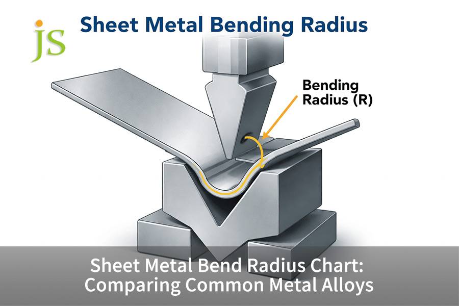

A sheet metal bending radius chart shows the minimum inside bend radius a blank can withstand without tensile fracture when air-bent on a press brake. Most shops use a baseline inside radius equal to the material thickness (1.0T), but the true engineering limits range from 0.5T to 6.0T depending on alloy elongation, temper, and rolling-grain orientation. Soft, ductile 5052-H32 aluminum can be bent to sharp radii of 0.5T–1.0T, whereas structural 6061-T6 aluminum and work-hardening stainless steels require 2.0T–4.0T bend radii.
Core Answer Summary Table
|
Alloy & Temper |
Elongation (%) |
Longitudinal Bend R_min (With Grain) |
Transverse Bend R_min (Across Grain) |
Typical Springback |
|---|---|---|---|---|
|
5052-H32 Aluminum |
12 |
1.0T |
0.5T |
1° - 2° |
|
6061-T6 Aluminum |
8 - 10 |
3.5T - 4.0T |
2.0T - 2.5T |
2° - 3.5° |
|
304/316 Stainless Steel |
40 - 50 |
1.5T - 2.0T |
1.0T |
3° - 6° |
|
1018 Cold Rolled Steel |
15 - 20 |
1.0T |
0.5T - 0.75T |
1° - 1.5° |
Elongation values from ASTM E8/E8M-22 and minimum bend radii from ASTM E290:2022.
Transverse bending across the rolling grain reduces fracture risk by 30% to 50%; high-strength alloys such as 6061-T6 must never have inside radius set below 2.0T.
How to Use a Sheet Metal Bending Radius Chart to Compare Alloy Limits?
A sheet metal bending radius chart matches raw alloy elongation against tensile strain on the outer boundary of a bend. Ductile alloys like 5052-H32 and 1018 steel support a minimum bending radius of 0.5T to 1.0T, while high-yield alloys including 6061-T6 and 304 stainless require 2.0T to 4.0T clearances and increased press-brake tonnage.
Calculation of external fiber strain and fracture mechanism
The equation for the tensile strain of the outer fiber is ε = 1 / (2R/T + 1). When the inner radius of the part is lesser than the critical threshold for the elongation of the material, the concentration of micropores at grain boundaries leads to macroscopic cracking. This is why 6061-T6 fractures when bent below roughly 2.0T (transverse) to 3.5–4.0T (longitudinal), while 5052-H32 survives bends down to 0.5T (transverse).
Multidimensional Alloy Comparison Matrix
|
Dimension |
5052-H32 Aluminum |
6061-T6 Aluminum |
304 Stainless Steel |
1018 CRS |
|---|---|---|---|---|
|
Recommended R/T Threshold |
0.5T - 1.0T |
2.5T - 4.0T |
1.0T - 2.0T |
0.5T - 1.0T |
|
Springback Compensation |
1° - 2° |
2° - 3.5° |
3° - 6° |
1° - 1.5° |
|
Tonnage Multiplier |
0.5x - 0.6x |
0.8x - 0.9x |
1.5x - 1.8x |
1.0x |
|
Failure Modes |
Surface indentation |
Through-thickness cracking |
Work hardening fracture |
Scale flaking |
304 stainless steel requires at least 1.5 times the tonnage; 6061-T6 is a high-fracture-risk alloy, and the 1T rule of thumb for low-carbon steel should never be used.
JS Precision Project Data (2025) — Internal press brake trials across 500+ bends on 2.5mm 5052-H32 and 6061-T6 verified the 0.5T and 3.5T thresholds respectively, with scrap rates 0.3% vs 14.2% when deviating from chart limits.
Reverse Failure Mode Analysis
- Surface indentation: if a very high press is used, this may cause the punch's tip to dig into the soft aluminium of the upper surface. You may either reduce force or use a larger punch radius to correct that.
- Thick-penetration brittle fracture: 6061-T6 will probably develop if R/T is < 2.5 and a minimal radius specification must be adhered strictly.
- Delayed cracking: Strengthening of 304 stainless steel leads to internal strain that can exceed 1,000 MPa, so an extra stress relief treatment is mandatory.
- Burr jamming: this can be the result of oxide-scale flaking from a sheet (1018 CRS). A polyurethane coating should be put on top of the blank.
Explore our Metal Bending Service for precision forming solutions covering all alloys.
How Does Bending Direction Determine the Minimum Bending Radius?
Bending direction directly governs the minimum bending radius by aligning grain boundaries either parallel or perpendicular to applied stresses. Transverse bending across the rolling grain allows uniform tensile strain distribution, enabling tighter inside radii. Longitudinal bending parallel to the grain channels strain along weak inclusions, increasing outer-surface cracking risk by up to 40%.
Microstructure Grain Orientation Effect
The elongation of the grains occurs during cold rolling process. On bending, the outer fibers go up tension: if the stress is parallel to the elongated grains (parallel to the grain), then the micropores propagate along the inclusion chains; if the stress is perpendicular to the grains (cross-grain), then strain is localized on multiple grain boundaries, and the ductility increases by 35%.
Quantitative test data of directional bending
The cold bending process of 6061-T6 and high-strength steel demonstrates that the longitudinal bending diminishes the effective elongation by 25% to 40%. cold bending 5052-H32 in the cross-grain direction permits very sharp radii, with an R/T as small as 0.5T, while in the longitudinal direction of bending at least 1.0T is needed.
Nested Strategy for Multi-directional Bending
The sheet blank rests at a 45° angle with the rolling direction. It is advisable to match the grain angles along the bending directions so that the bending stress is equally distributed along the grain. This practice can reduce directional scrap from complex enclosures by up to 60%.
Transverse bending can handle 35% higher external surface strain than longitudinal bending. Even so, in longitudinal bending, the minimum radius safety factor should be increased by 1.5 to 2.0 times to avoid fracture.
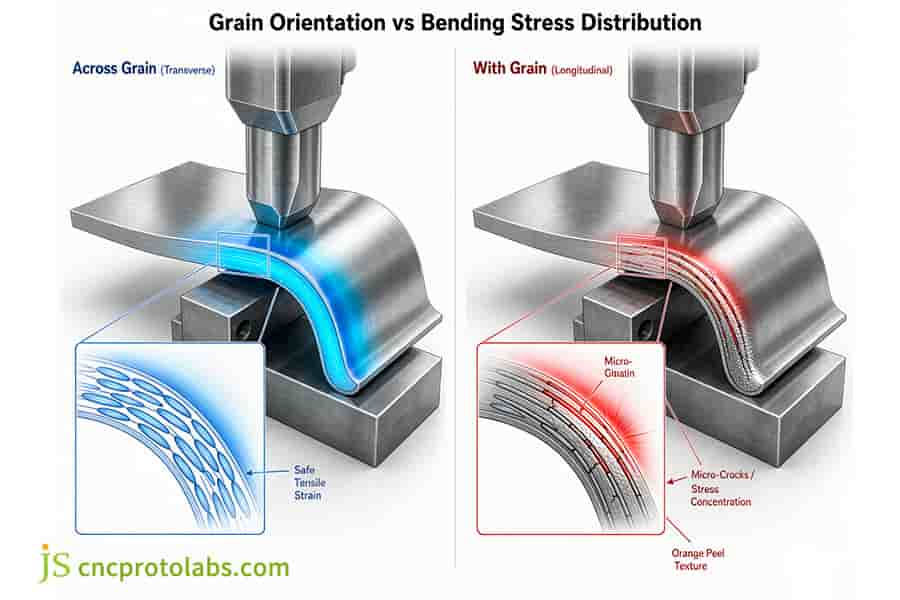
Figure 1: Diagram comparing across grain and with grain bending stress distribution on sheet metal.
Aluminum vs Stainless Steel: Which Is the Best Aluminum Alloy for Bending?
When evaluating aluminum vs stainless steel for forming limits, identifying the best aluminum alloy for bending depends on balancing ductility against strength. While 5052-H32 delivers tight, crack-free radii down to 0.5T with minimal springback, austenitic 304 stainless steel demands 1.0T to 2.0T clearances and generates intense work hardening, requiring nearly double the press-brake tonnage.
Comparison of elongation and crack sensitivity
304 stainless steel reaches an elongation level of 45% or even more. Still, a martensitic phase change occurs during cold forming or bending operation, which results in major work hardening. 5052-H32 aluminum alloy reaches approximately 12% elongation. A low yield strength enables its smooth plastic deformation; also, it has very low sensitivity to external fiber micro-tears (less than 0.5T).
Springback Dynamics and Compensation
- Use a linearity compensation model where a springback after forming of the aluminum alloy is 1-2 degrees.
- A springback of 3-6 degrees with austenitic stainless steel calls for the use of CNC closed-loop angle control.
- High-resilience steel requires stroke correction via a real-time feedback system.
Cross-process substitution boundaries
When one part is quite thick (over 6mm), the forming radius is less or equal to material thickness R ≤ 1.0T and the component needs good rigidity, cold forming will cause a load limit on the sheet metal press brakes. Under this situation, 5-axis CNC milling directly from sheet metal block is a suitable alternative solution.
Why Avoid Bending 6061 T6 Aluminum for Tight Enclosure Brackets?
Engineers must exercise caution when bending 6061 t6 aluminum for compact electronic brackets, as its low 9% elongation triggers severe outer-radius fractures under sharp radii. Substituting the profile with 5052-H32 permitted an exact 1.0T bend radius, dropping part scrap from 14.2% to 0.3% during precision sheet metal bending at JS Precision .
Initial Design Bottlenecks
- A customer came up with a 2.5 mm load carrying bracket and went with 6061-T6 to endure 40kg cyclic loads.
- The internal DIN-rail clash constrains the inside radius to R = 3.0 mm (1.2T), which is far below the recommended 2.0T safety factor.
- The first test item showed continuous microcracks running along the fold, so they ended up scrapping 14.2%.
Trade-off Analysis
|
Parameter |
Original (6061-T6) |
Revised (5052-H32 + Stiffening Ribs) |
|---|---|---|
|
Design Inside Radius |
3.0mm (1.2T, over-limit) |
2.5mm (1.0T, compliant) |
|
Scrap Rate |
14.2% |
0.3% |
|
Springback Variation |
3.2° ± 0.8° |
1.5° ± 0.2° |
|
Relative Cost |
100% |
81.5% |
Contact a JS Precision engineer for a free DFM feasibility analysis . Explore more Sheet Metal Enclosure Manufacturing and DFM Case Studies .
How Does Bending Steel Sheet Differ from Bending Stainless Steel Sheet Metal?
Bending steel sheet like 1018 cold-rolled steel shows about 1° of springback and work nicely with radii from 0.5T to 1.0T. Versus that, bending stainless steel sheet metal will result in a great work hardening and springback that can be even 3 to 6 degrees. Stainless steels typically require 1.5-1.8 times more shaping tonnage and larger V-die openings ranging from 8T to 10T.
V-die opening selection
|
Material |
Recommended V-Die Opening |
Natural Inside Radius (Air Bend) |
Springback Range |
|---|---|---|---|
|
1018 CRS |
6T - 8T |
R ≈ V/6 |
1.0° - 1.5° |
|
304 Stainless Steel |
8T - 10T |
R ≈ V/5 |
3.0° - 6.0° |
Smaller mold openings on stainless steel can exceed the contact stress limit, accelerating wear and causing die biting.
Rebound Pre-compensation
- The 1018 CRS has a springback of 1.0° to 1.5°, which can be compensated for by fixing the bending amount.
- Stainless steel requires 3.0° to 6.0° of bending travel compensation, which needs to be dynamically adjusted.
- An 85° or 80° punch is typically used to achieve the final 90° angle.
Surface Contamination Control
- A polyurethane film interlayer must be used to isolate the carbon steel mold from the stainless steel surface.
- Alternatively, use chrome-plated special tools to prevent iron particles from embedding.
- This prevents the passivation layer from being damaged and inducing corrosion.
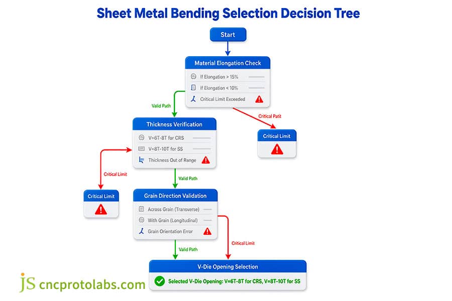
Figure 2: Sheet metal bending selection decision tree for calculating bend radius.
How Does a Bending Radius of Sheet Metal Chart Guide Calculating Bending Radius?
Referring to a bending radius of sheet metal chart gives you the basic geometry you need in bending radius calculations to get your K-factors right. As the inside radius to thickness ratios (R/T) go from 0.5 to 3.0, the position of the neutral axis changes, which means K-factors will change too from 0.30 to 0.48.
Derivation of unfolded dimensions
Formula: BA = (π / 180) × A × (R + K × T). When R < 1.0T, the coefficient K shrinks to 0.30 - 0.35; when R ≥ 3.0T, the coefficient K stabilizes at 0.46 - 0.50.
Level 4 Selection Engineering Branch
- Limit of ductility: Calculate R/T to obtain minimum threshold from elongation of material.
- Grain direction Check: the effect of parallel vs. cross grain on cracking and springback is identified.
- Mold of free formed comparison: Check if the mold opening corresponds to the inner radius.
- Fixation of CAD unfolded dimensions: the actual K coefficient is measured, used for reverse calculation.
Experimental K-Factor Expanded Quick Reference Matrix
|
Material |
K at R/T = 0.5 |
K at R/T = 1.0 |
K at R/T = 2.0 |
K at R/T ≥ 3.0 |
|---|---|---|---|---|
|
5052-H32 |
0.33 |
0.38 |
0.42 |
0.46 |
|
6061-T6 |
Not recommended |
0.36 (fracture risk) |
0.40 |
0.45 |
|
304 Stainless |
0.32 |
0.37 |
0.43 |
0.48 |
|
1018 CRS |
0.35 |
0.40 |
0.44 |
0.48 |
The K coefficient must be calculated by reverse calculation using the natural inner radius of the actual mold in the workshop.
ISO 7438:2020 — Metallic materials — Bend test specifies test piece dimensions and punch diameters for verifying ductility.
SME Technical Paper (2024) — Neutral Axis Shift in Air Bending of High-Strength Alloys quantifies K-factor variation across R/T ratios.
Visit the Sheet Metal K-Factor&Flat Layout Calculation Guide to master accurate K-factor calculation methods and improve your sheet metal unfolding efficiency.
FAQs
Q1: What happens if the bend radius is smaller than the minimum limit?
When the outer-fiber tensile strain exceeds the material elongation, micro-voids coalesce along grain boundaries, progressing from orange-peel rippling to fracture. Micro-cracks let plating or acid solutions penetrate and cause deep-layer corrosion failure.
Q2: Can 6061-T6 aluminum be bent with a 1T inside radius without cracking?
Cold bending 6061-T6 at 1T causes brittle fracture. If a 1T radius is a design requirement, order 6061-O temper, form at 1T, then solution-heat-treat to T6—or use 5052-H32 with stiffening ribs.
Q3: Why does stainless steel exhibit significantly greater springback than mild steel?
304/316 austenitic stainless steel is characterized by very low yield-to-tensile strength ratio, work hardening rate is extreme and they have a relatively high elastic modulus. The elastic strain energy stored during the bending process is a lot greater than in mild steel leading to springback of the order of 3° to 6° against the mild steel springback of 1° to 1.5°.
Q4: What is the standard V-die opening ratio for air bending sheet metal?
For mild-steel sheet and soft-aluminum sheet the V should equal 6T to 8T. For stainless-steel sheet and high-strength-aluminum V should be 8T to 12T. For thick plate (T ≥ 6mm) V should be ≥ 10T to keep the press brake loading moderate.
Q5: How do I choose between 5052 and 3003 aluminum for sheet metal bending?
3003-H14 allows for easier very sharp-radius forming but offers the poorest indentation resistance. 5052-H32 has highest corrosion resistance, the strongest structural properties and it is capable of 1T bending, this material has become the standard in manufacturing industrial enclosures.
Q6: How does grain orientation affect bend angle consistency?
Longitudinal bending increases elastic recovery scatter due to yield point variation, widening batch angle tolerance from ±0.5° to ±1.5°, degrading automated assembly accuracy.
Q7: Is a zero inside radius (sharp bend) practical in modern precision sheet metal bending?
Sharp bends physically don't happen. Forcing the metal to zero radius ruins the punch tip, tears apart the outer most grain layers at the outer bend, and causes cracks. Modern manufacturing standards strictly forbid zero-radius design.
Q8: How do I calculate bending tonnage when enlarging the bend radius?
With larger radius punches the contact area is greater which implies deeper stroke and more force is needed. Counteract with enlarging the V-die opening proportionally to keep the tonnage under the bending press brake power and at the same time, overcoming material flow stress.
Summary
Precisely setting the inner bending radius of sheet metal is a key step in balancing structural rigidity, surface quality, and production yield. By considering material elongation, rolling crystal orientation, and tool geometry during blanking, over 90% of external fiber cracking and springback deviations can be eliminated.
Evaluating the feasibility and tolerance fit of bending complex structural components? Contact our technical team to obtain free DFM feasibility analysis and batch forming solutions. For complex industrial enclosures requiring tight dimensional tolerances across high-strength aluminum or stainless alloys, explore precision sheet metal bending at JS Precision to validate tooling setups and eliminate structural production scrap.

Disclaimer
The contents of this page are for informational purposes only. For JS Precision Services, there are no representations or warranties, express or implied, as to the accuracy, completeness, or validity of the information. It is the buyer's responsibility to identify specific technical requirements and request a formal parts quotation. Please contact us for more information.
Resource

