English



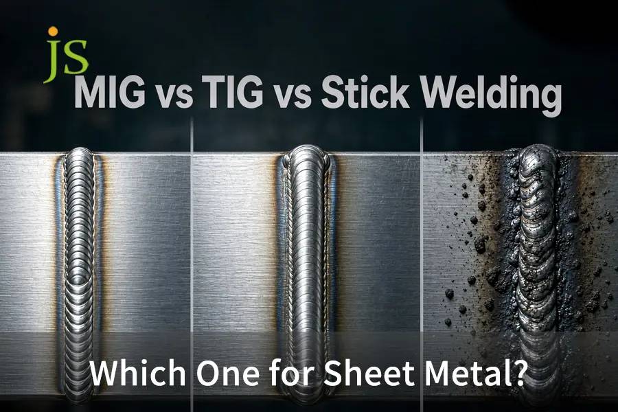

For sheet metal fabrication under 3 mm (11 Gauge), TIG welding is preferred for high-precision, visually appealing, and thin-gauge joints down to 24 Gauge (0.6 mm). Pulsed MIG welding offers strong cost-effectiveness and fast mechanical performance on structural assemblies from 18 to 11 Gauge. Stick welding (SMAW) is not suitable for precision thin gauges because its high heat input (>1.2 kJ/mm) leads to immediate burn-through and significant warping.
In precision manufacturing, MIG vs TIG vs Stick welding represents the core trade-off among deposition rate, heat input density, and thermal distortion for cold-rolled steel, aluminum, and stainless steel assemblies.
Sheet Metal Welding Process Selection Matrix
Engineering Takeaway: TIG welding provides the greatest geometrical accuracy and no post-weld grinding on decorative and thin workpieces, while pulsed MIG welding provides the least cost per unit for structural fasteners, Stick welding should be eliminated from thin sheet metal manufacturing owing to uncontrollable burn-through problems.
| Welding Process | Thickness Range | Heat & HAZ Control | Travel Speed | Primary Failure Mode on Thin Sheet |
| TIG (GTAW) | 0.5–3.0 mm (24–11 Ga) | Foot-pedal arc tuning, HAZ ≤1.5 mm | 80–200 mm/min, Slow manual run | High labor cost, Rejects joint gaps >0.2 mm |
| MIG (GMAW) | 1.0–6.0 mm (19–3 Ga) | Pulsed control, HAZ 2.0–4.0 mm | 300–600 mm/min, Fast production | Burn-through <1.0 mm, Spatter cleanup needed |
| Stick (SMAW) | ≥3.2 mm (≥10 Ga) | Coarse arc transfer, HAZ ≥5.0 mm | Interrupted by slag chipping | Instant blowout, Warpage, Slag pockets |
Stick (SMAW) applies only above ~3.2 mm (plate range), so it is listed here as the process to exclude from thin-sheet work.
MIG vs TIG vs Stick Welding: Which Is the Best Welding for Sheet Metal?
When evaluating MIG vs TIG vs Stick welding to identify the best welding for sheet metal, the selection will depend on the thickness, cosmetic considerations, and part tolerances. While TIG welding is second to none in terms of thin material less than 1.5 mm without any spatter, pulsed MIG will excel at structural welding of 1.5 mm to 3.0 mm.
The Physics of Heat Input and Sheet Metal Distortion
Thin sheets cannot dissipate excess heat quickly. The energy transferred to the workpiece follows the heat input formula:
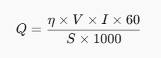
- Q: Net heat input (kJ/mm)
- η: Thermal efficiency factor (GTAW: 0.6, GMAW: 0.8, SMAW: 0.85)
- V: Arc voltage (Volts)
- I: Welding current (Amperes)
- S: Linear travel speed (mm/min)
SMAW (Stick) combines a high efficiency factor (η= 0.85) with slow travel speeds, concentrating destructive energy into thin sections. This results in a very uneven thermal expansion, sheet buckling (oil-canning), and dimensional scrap. Technical fundamentals about arc physics can be found in our article about how metal welding works.
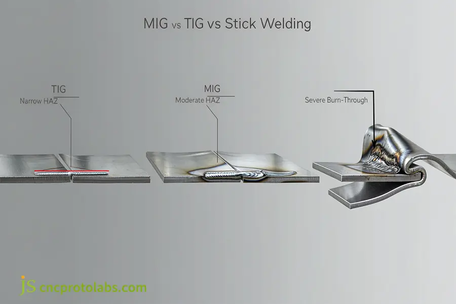
Cross-sectional analysis of heat-affected zones (HAZ) during mig vs tig stick welding on thin sheet metal.
Base Material Sensitivity Across Common Alloys
The various sheet alloys exhibit different behaviors during localized heating cycles:
Cold-Rolled Mild Steel (SPCC / AISI 1018)
- Gauge Range: 22 Ga to 12 Ga (0.8 mm to 2.5 mm).
- Thermal Properties: Expansion of 12.0 μm/m·K; conductivity of 50.0 W/m·K.
- Welding Behavior: According to ASTM A1008/A1008M-21a, consistent chemical composition and surface cleanliness allow for easy welding of mild steel. This material is able to bridge joints without pulsing during short-circuit MIG.
Austenitic Stainless Steel (AISI 304 / 316)
- Gauge Range: 24 Ga to 14 Ga (0.6 mm to 2.0 mm).
- Thermal Characteristics: Expansion of 17.3 μm/m·K; conductivity of 16.2 W/m·K.
- Fabrication Performance: Welding Characteristics: Due to conductivity being one-third of that of carbon steel, heat gets localized at the puddle. Due to the high rate of expansion, severe distortion and carbide precipitation will result without use of pulsed TIG welding process.
Wrought Aluminum Alloys (5052-H32 / 6061-T6)
- Gauge Range: 20 Ga to 10 Ga (0.9 mm to 3.2 mm).
- Thermal Characteristics: Thermal expansion of 23.8 µm/m.K, thermal conductivity of 138.0 W/m.K.
- Fabrication Performance: Native surface oxidation (Al2O3) melts at 2072°C, the interior alloy melts at 660°C. Welding thin aluminum needs a quick burst of high-frequency AC at the start, followed by a fast drop in current to prevent burnouts.
When Does MIG Welding Sheet Metal Maximize Production Efficiency?
MIG welding sheet metal provides superior deposition rates and productivity (300-600 mm/min) on gauges from 18 to 11 Ga (1.2-3.0 mm), reducing time consumption by 60% as compared to TIG. When comparing Stick welding vs MIG for sheet metal, the use of short arc and pulsed GMAW allows precise control over drop transfer without burn-through hazards.
Arc Transfer Modes: Short-Circuit vs. Pulsed Spray
Standard spray transfer is too hot for sheet metal. Production shops use two controlled transfer modes:
- Short-Circuit Transfer (GMAW-S): Contact between the wire and molten puddle causes a drop in voltage and spike in amps, releasing 50 to 200 drops per second. With ER70S-6 wire measuring 0.023 in (0.6 mm) or 0.030 in (0.8 mm), it joins gaps with minimal spatter in 18 Gauge (1.2 mm) steel.
- Pulsed-Spray Transfer (GMAW-P): A pulsed inverter switches between low background and high peak currents to produce one droplet without contacting the material. It decreases the heat input on average by 35% when compared with short circuiting, allowing fast joining of 16 Gauge (1.5 mm) aluminum and stainless steel. For mechanical limitations of MIG welding across varying gaps, consult the comparative analysis of laser vs MIG weld strength.
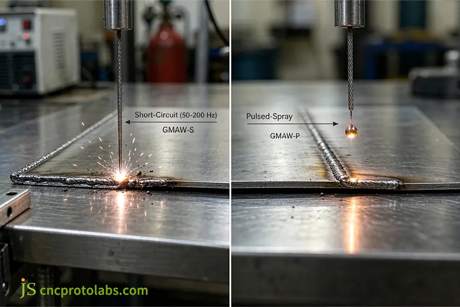
Arc transfer modes utilized during precision mig welding sheet metal operations.
Breakdown of Total Welding Cost: TIG vs. MIG
Although pulsed MIG tools are more expensive upfront, the saving on labor is the biggest factor in production costs. When considering the TIG vs MIG cost per hour sheet metal, the arc time, gas used and final grinding are what affects the overall amount of money spent. See our detailed welding fabrication cost breakdown to compare the operating costs.
| Cost & Speed Metric | TIG (Manual, 16 Ga Steel) | MIG (Semi-Auto, 16 Ga Steel) | Shop-Floor Impact |
| Travel Speed | 100–150 mm/min | 350–500 mm/min | MIG runs 2.5× to 3.5× faster on straight seams |
| Shielding Gas | 100% Argon (8–12 L/min) | 75/25 Ar/CO2 (12–15 L/min) | MIG gas mixes cut bottle costs by ≈25% |
| Grinding Labor | 0.05 hr/m (Spatter-free) | 0.25 hr/m (Chipping/sanding) | TIG eliminates surface cleanup and blending steps |
| Labor Cost (10m Pass) | High ($60–$90) | Low-to-Moderate ($25–$45) | MIG lowers overall piece price on structural parts |
Why Is TIG Welding Sheet Metal the Superior Choice for Thin Precision Parts?
TIG welding sheet metal is the benchmark for gauges under 1.5 mm (16 Ga) because non-consumable tungsten electrodes decouple arc heat from filler metal feeding. Often referred to as precision welding, high-frequency pulsed TIG limits the heat-affected zone to under 1.5 mm, answering why is TIG or MIG better for thin metal when requirements mandate zero spatter, minimal distortion, and aerospace-grade cosmetic finish.
Decoupled Thermal Regulation Mechanism
In MIG and Stick, higher current deposits more wire automatically. TIG separates heat input from material addition:
- Independent Arc Heat: The arc strikes between a non-consumable tungsten electrode (AWS EWTh-2 or EWLa-1.5) and the workpiece under argon, creating a puddle without adding filler.
- Manual Wire Addition: The welder introduces cold wire into the puddle edge only after verifying base fusion.
High-Frequency Inverter Pulsing (100–500 Hz)
To weld thin sheet without burnouts, inverter power supplies alternate output between two current levels:
- Peak Current Phase: A short high-amperage burst penetrates the seam, cleans surface oxides, and fuses the joint without overheating surrounding metal.
- Background Current Effect: The current instantly reduces to a lower constant level, cooling down the puddle in microseconds, but maintaining the arc alive.
- Thermal and Metallurgical Results: The arc cone is compressed and the HAZ is confined to 1.5 mm. No warpage, grain growth or burnouts on substrates thinner than 1.0 mm. For thermal comparison data, see our review of the laser vs TIG welding (HAZ).
Joint Fit-Up Requirements and Aesthetic Standards
TIG beads can comply with AWS D17.1 / D17.1M (Specification for Fusion Welding for Aerospace Applications). To do this, you have to have a very TIGht fit-up:
- Root Gap Limits: Edges should be 10% of sheet thickness (t). For 18G stock, edges should be ≤0.15mm. Larger edges are more likely to cause blowouts and melting.
- Edge Preparation: Joint edges shall be degreased and free from mill scale and oxides.
- Aluminum Cleaning: Mechanical stainless wire brushing must be carried out to remove oxides on the surface before welding.
Why Does Stick Welding Sheet Metal Often Result in Severe Burn-Through?
Stick welding sheet metal thinner than 18 Gauge (1.2 mm) is technically impractical because minimum arc strike currents (typically >40 A) concentrate uncontrolled energy on thin cross-sections. On questions like can you weld 20 gauge sheet metal with Stick, the process immediately results in thermal burn-through, high spatter, and slag inclusions that penetrate the dimensional and structural limits.
Physical Electrode Constraints and Minimum Current Thresholds
SMAW operates with flux-coated consumables rods needing lower current to maintain arc stability:
- AWS E6013 (1/16 in / 1.6 mm): Will take 40–55 A. Calls for at least 16 Gauge (1. 5 mm) sheet with copper chill bars.
- AWS E7018 (3/32 in / 2.4 mm): Needs 70–100 A. Unsafe under 12 Gauge (2. 7 mm).
- AWS E6010 (3/32 in / 2.4 mm): Requires 60–85 A. Very strong arc force makes tiny holes in thin sheets.
Arc drawing 45 A current on 20 Gauge (0.9 mm) sheet delivers energy faster than the metal can dissipate it, making holes in the joint.
Slag Entrapment and Secondary Post-Processing Effects
Despite the use of DCEN polarity on 16 Gauge plate, Stick causes damage to the structure:
- Slag Inclusions: The low temperature is incapable of floating off molten slag, resulting in entrapment of brittle slag pockets within the joint.
- Chipping Damage: Chipping with the help of chipping hammers or needle scalers causes dents to the thin metal sheets.
- Parent Metal Thinning: Grinding of irregular welds causes thinning of sheet metal below the designed tolerance limit.
Welding rod will only be practical for repairing outdoor structural work. When assessing heavy assemblies where welding is impractical, consider choosing between welding and casting for structural alternatives.
How Should Engineers Balance MIG vs TIG for Sheet Metal Fabrication?
Balancing MIG vs TIG for sheet metal requires evaluating sheet gauge, structural integrity, and secondary finishing overhead. In considering technical differences between MIG and TIG and Stick welding, TIG is better in precision and heat control under 1.5 mm sheet, while pulsed MIG is more efficient in assemblies greater than 1.5mm.
MIG vs TIG vs Stick Shop-Floor Selection Matrix
Engineering Takeaway: TIG gives the TIGhtest dimensional accuracy and lowest reject rate on thin visible panels, pulsed and short-circuit MIG offers the lowest overall fabrication cost on structural hardware over 1. 2 mm, Stick is not structurally acceptable for precision sheet metal.
| Evaluation Vector | TIG (GTAW) | Pulsed MIG (GMAW-P) | Short-Circuit MIG (GMAW-S) | Stick (SMAW) |
| Tolerance (GD&T) | Superior (±0.25 mm), Low wave warp | High (±0.50 mm), Low buckling | Moderate (±0.80 mm), Needs stitch runs | Unusable (>±2.0 mm), Severe warp |
| Deposition & Speed | Low (0.2–0.5 kg/hr), Slow line runs | High (2.0–4.0 kg/hr), Fits cobots | Very High (1.5–3.5 kg/hr), Fast manual | Low-to-Moderate, Interrupted run |
| Cosmetics & Cleanup | Clean ripple, Zero spatter, No grind | Clean, Light spatter, Quick polish | Moderate spatter, Needs chiseling | Heavy slag, Rough seam, Heavy grind |
| Shop Failure Points | High skill barrier, Rejects gap >0.2 mm | High machine cost, Needs torch angle | Lack-of-fusion risks on heavier tabs | Instant blowouts, Slag pockets |
A 4-Step Workflow for Determining Welding Routes in the Workshop
Part processes on the manufacturing shop floor can be effectively scheduled with the four-step screening process:
- Step 1: Evaluate the thickness of the material if your material is less than 1.2 mm (18 Ga) then TIG weld it, if larger then move on to step 2.
- Step 2: Look for visual weld requirement. If the weld shows and surface has a coating, TIG it to prevent grinding marks, else proceed to Step 3.
- Step 3: Assess production quantity and weld length. If the quantity is greater than 500 parts and weld length is longer, use pulsed MIG (with automation or collaborative robotic help), otherwise, use manual short-circuit MIG or manual TIG.
- Step 4: Determine the alloy. For aluminum below 2.0 mm (14 Ga), use AC pulsed TIG (for oxide breakdown and avoiding melt pool collapse), for steel and stainless steel above 1.5 mm, use MIG welding.
Structural differences are covered in our MIG vs TIG welding guide. When doing contract manufacturing runs, qualified sheet metal welding services make sure parts hold drawing tolerances and inspection specifications.
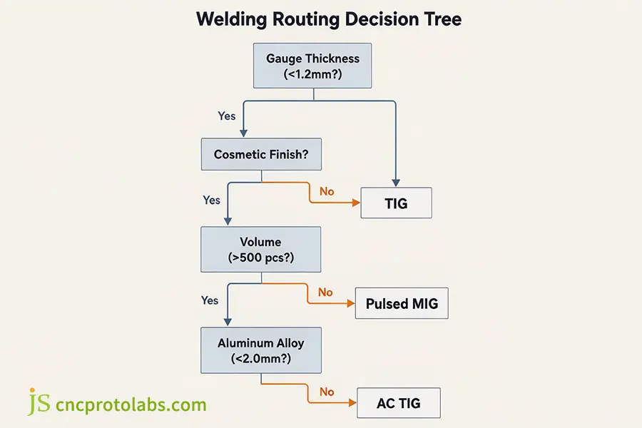
Shop-floor decision tree for optimizing sheet metal welding process routing.
FAQs
Is TIG or MIG better for thin metal?
TIG is clearly superior when working with thin metal less than 1.5 mm (16 Ga) since non-consumable tungsten electrodes facilitate independent amperage control using a foot pedal and avoid burn-throughs. Short circuit MIG can be employed on 16-18 Ga metal, but it carries greater risks of burn-throughs and spatter with very thin metals, while TIG will maintain the quality of the joints down to 0.5 mm.
What is the best method for welding aluminum sheet metal?
AC TIG with high-frequency arc stabilization is the premier method for thin aluminum sheet (<2 mm) to effectively clean the refractory aluminum oxide layer (Al2O3) without overheating the core. For panels thicker than 2.5mm pulsed MIG with a push-pull gun gives an even more efficient result as the heat is managed.
Can you weld 20 gauge sheet metal with Stick?
Stick welding 20 gauge (0.9 mm) sheet metal is strictly not recommended in production environments because standard flux-coated electrodes operate at currents that immediately burn through thin sheets. It causes severe burnouts and heavy slag, precision pulsed MIG or TIG should always be specified instead.
Can Stick welding ever be used on sheet metal assemblies?
Stick is only used on heavy-gauge (>10 Ga / 3.2 mm) structural sheet metal or less critical outdoor field repair work in which shielding gas is lost to wind. In precision sheet metal enclosure or chassis work, Stick is precluded to preserve GD& T geometry.
How do TIG and MIG compare in cost per hour for sheet metal fabrication?
TIG has higher direct labour costs from lower feed speeds (~100mm/min), so 40-50% more expensive per linear metre for initial welding. Yet, due to zero spatter, cleaner ripples and better aesthetics, as well as no need for secondary grinding, net cost for high cosmetic components is less than MIG.
Conclusion
Selecting the right welding process for sheet metal balances gauge thickness, cosmetic requirements, and volume. TIG is preferable for thin enclosures and precision hardware below 1. 5 mm to maintain the close tolerances and avoid burnouts, while structural assemblies ranging from 1. 5 mm to 3. 0 mm can be produced at lower unit cost through pulsed MIG technology. Stay away from Stick welding for precision thin-gauge fabrication to avoid distortions and rejected parts.
Assessing welding processes, material thicknesses, or stress-related distortion risks of parts at the early design stage will save costly redesigns in later phases. Send your 3D CAD models and tolerance requirements directly to the experts at JS Precision for an engineering DFM, joint fit-up, and process review.
Resource