 English



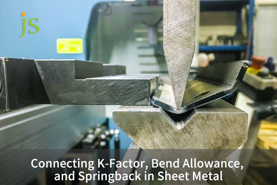

In precision sheet metal manufacturing, three values decide whether a formed part matches the drawing. The K-factor is a dimensionless constant (K = t/T) that describes how far the neutral layer — the plane that neither stretches nor compresses — has moved from the inside face. Bend allowance (BA) is the developed arc length of that neutral layer, added to the flange lengths to get the flat blank. Springback (Δθ) is the angle the part opens back up by, caused by elastic recovery once the punch releases. These three factors, along with sheet thickness, inner corner radius, and material elastic modulus, form a complete closed loop for predicting unfolded dimensions.
Core Answer Summary Table
The accuracy of the dimensions of the unfolded sheet metal mainly comes from the computation of unfolding compensation based on neutral layer offset and the geometric correction of the material unloading springback through overbending.
|
Core Parameter |
Physical Definition |
Typical Engineering Range |
Core Control Objective |
|---|---|---|---|
|
K-Factor (K) |
Ratio of neutral layer depth to sheet thickness (t/T) |
0.30 to 0.50 (Nominal 0.44 for mild steel) |
Determine the location of the neutral layer with zero tensile/compressive stress. |
|
Bend Allowance (BA) |
Developed arc length of the material's neutral layer along the bend |
Calculated based on inside radius, sheet thickness, and bend angle |
Determine the flat pattern blank size for CAD/CAM. |
|
Springback (△θ) |
Elastic angular recovery after punch pressure is released |
0.5° to 4.0° (depending on material yield ratio) |
Determine tooling design and overbend compensation. |
Sources: general tolerances per ISO 2768-1:1989; cold-bending K baselines per DIN 6935:2011.
How Do You Calculate the Neutral Axis in Sheet Metal Bending?
Sheet metal bending calculations determine the developed flat blank length by tracking the neutral axis. During plastic deformation, the neutral axis shifts inward from the material centerline (0.50T) toward 0.33T to 0.44T as the inside bend radius tightens relative to thickness. Calculating exact bend allowance requires factoring in the inside radius, bend angle, sheet thickness, and dynamic K-factor to prevent dimensional expansion errors after forming.
How Do Tension and Compression Distribute Through the Sheet Thickness?
- Outer surface gets stretched under biaxial tensile strain: material on the outside of the bend elongates, so the spacing between fibres increases. Tensile strain rises through the thickness toward the outer face.
- Inner surface is strained in biaxial compression: material on the inside shortens. Because of this, the neutral layer — the plane that carries zero stress and zero strain — migrates inward.
- The shift is dynamic: as R/T decreases, the neutral axis moves from 0.50 T toward 0.33 T, which shortens the developed (flat) length. This occurrence is called the neutral axis shifting under plastic deformation and it is one of the major variables whose quantitative determination is essential in bending calculation for sheet metal.
Standard expansion calculation formula and parameter analysis
Core formula:
BA = (π/180) × A × (R + K × T)
Where:
- A = bend angle in degrees
- R = inside bend radius (mm)
- K = K-factor (dimensionless)
- T = sheet thickness (mm)
- Units: keep every parameter consistent — for example, T = 2.0 mm, R = 2.0 mm, A = 90°.
- Engineering implication: the neutral layer position directly sets the blank size, so the laser-cutting kerf width has to be reconciled with the developed length before nesting the flat pattern.
For the definition and derivation of K itself, see What Is K Factor in Sheet Metal Bending?.
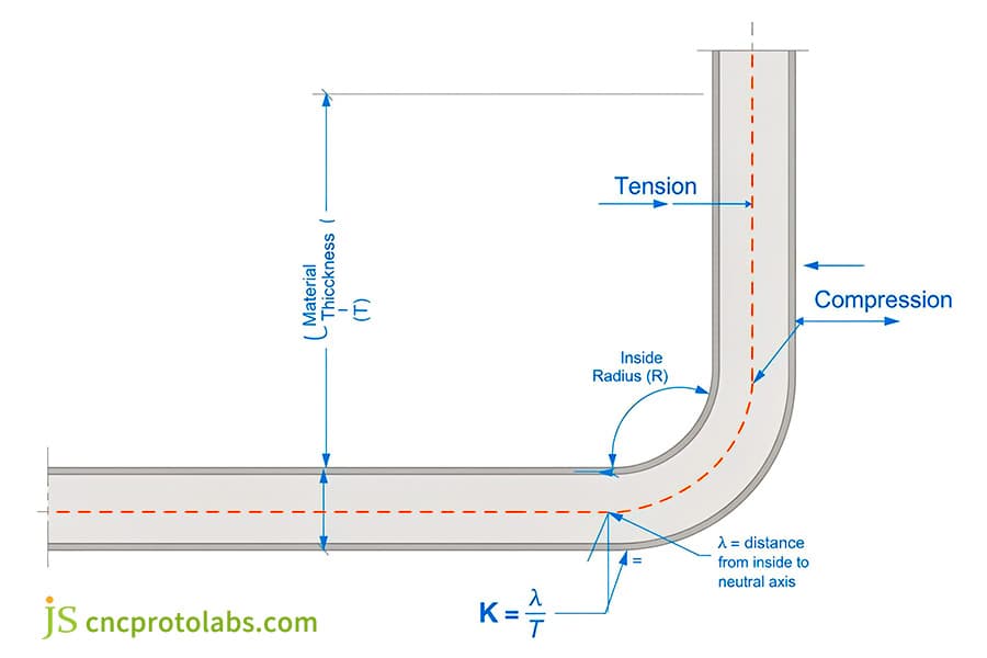
Figure 1: Schematic diagram of strain distribution in sheet metal section.
What Is the Difference Between Bend Allowance and Bend Deduction?
Bend allowance adds the exact length of the neutral axis arc to the flat lengths of the two flanges. Conversely, bend deduction subtracts the geometric apex expansion from the sum of the overall outside dimensions. Both methods yield identical flat patterns when calibrated against verified bending allowance charts, differing only in whether CAD operators measure from internal tangent points or external virtual apexes.
Geometric datum differences between addition logic and subtraction logic
- Bend allowance (BA): the neutral plane arc length is simply added to the flange lengths; the measurement reference is at the inside tangent point.
- Bend deduction (BD): starts from the summed outside dimensions and subtracts the outside setback (OSSB = R + T) at the virtual apex where the two outer faces would meet.
- The two are equivalent: when BA and BD are derived from the same K-factor, they produce exactly the same flat length. Knowing which method your CAD system uses tells you which numbers to enter.
Measurement tolerance effects of 90° and obtuse/acute angle bends
- 90° bend: BD = 2 × (R + T) − BA. This case is the least sensitive to measurement error.
- Obtuse-angle bends: outer-contour measurements amplify angular error, so use the BA (addition) method.
- Acute angle bending: the inner tangent point is hard to locate, so the BD (subtraction) method keeps the part centred in the die more reliably.
Limitations of the Bending Compensation Quick Reference Table
- Depends on the die opening (V width): for the same material, the measured K value shifts by ±0.03 across different V openings, so any quick-reference table has to state the V width it was measured at.
- Depends on the punch tip radius: the BA values here assume R_punch = 1.0 T. Change the punch radius and you have to recalibrate.
- Air bending only: the values apply to air bending. Bottoming needs an extra 0.04–0.08 on K. Rather than trusting a chart, run a test coupon and measure — that is the only calibration that survives a material batch change.
These are calculation starting points, not a substitute for a test bend. Your die opening, punch radius, material batch and rolling direction will all shift them — expect ±0.03 on K and ±0.5° on springback between batches.
|
Material |
Thickness T (mm) |
Punch Radius R (mm) |
Empirical K-Factor |
90° BA (mm) |
90° BD (mm) |
|---|---|---|---|---|---|
|
SPCC Cold Rolled Steel |
1.0 |
1.0 |
0.44 |
2.26 |
1.74 |
|
SPCC Cold Rolled Steel |
2.0 |
2.0 |
0.42 |
4.46 |
3.54 |
|
5052-H32 Aluminum |
1.5 |
1.5 |
0.41 |
3.32 |
2.68 |
|
304 Stainless Steel |
2.0 |
2.0 |
0.37 |
4.30 |
3.70 |
|
6061-T6 Aluminum |
3.0 |
3.0 |
0.39 |
6.55 |
5.45 |
Worked example (row 1): R + K × T = 1.0 + 0.44 × 1.0 = 1.44 mm; BA = (π/180) × 90 × 1.44 = 2.26 mm; BD = 2 × (1.0 + 1.0) − 2.26 = 1.74 mm. All rows assume air bending, A = 90°, R/T = 1.0. BD = 2 × (R + T) − BA.
Flat-pattern development should be dimensioned and toleranced per ASME Y14.38-2020 (Dimensioning and Tolerancing), with general tolerances taken from ISO 2768-1:1989. Both are referenced here only for drawing convention — the BA and BD values above are calculated, not standardised.
Before releasing a drawing, check the formed dimensions against JS Precision's sheet metal tolerance guide to confirm that the forming dimensions comply with ISO 2768-m.
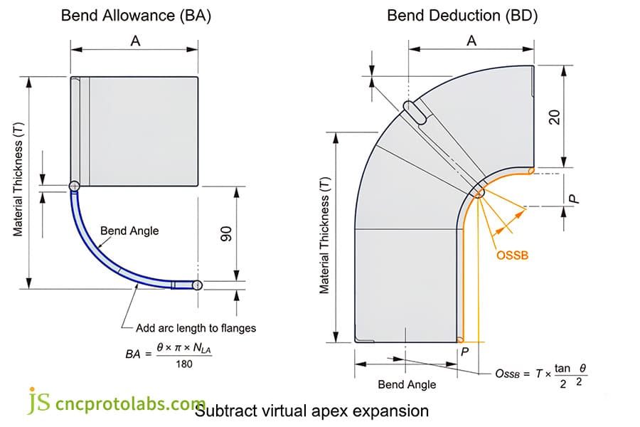
Figure 2: BA and BD measurement geometry diagram.
How Does Air Bending Sheet Metal Counteract Material Springback?
Air bending counteracts springback by overbending the workpiece past the target angle, so the part relaxes to the design angle when the punch retracts. High-yield metals such as 6061-T6 aluminium spring back by up to 4° because of their high yield-to-modulus ratio, so they need adaptive stroke-depth programming and careful V-opening selection to hold the finished angle.
How Do Air Bending, Bottoming, and Coining Differ in Springback?
- Air bending: the workpiece touches only the punch tip and the die shoulders, so springback after unloading is large and has to be compensated. In air bending, punch depth (stroke) is the variable that controls this compensation.
- Bottoming: the high tonnage forces the material to flow into the die shape, which reduces springback to 0.5°–1.0° but shifts the effective K-value up by 0.04–0.08.
- Coining: localized plastic flow at the tool–part interface removes almost all elastic strain, leaving negligible springback — but at the cost of much higher die wear and required tonnage.
How Does the Yield-to-Modulus Ratio (σ_y/E) Govern Springback?
- Yield strength σ_y: the stress at which the material begins to deform plastically, in MPa.
- Elastic modulus E: the material's resistance to elastic deformation, in GPa.
- Elastic recovery ratio (σ_y/E): the higher this ratio, the more severe the springback. See the table below for values —— note that σ_y is in MPa and E in GPa, so the ratio is on the order of 10⁻³, not 10⁻¹.
How Do Grain Direction and R/T Affect Cracking in 6061-T6?
- Bending parallel to the rolling direction: plasticity drops, the K-value falls by 0.02–0.03, and springback can reach 3.0°–4.0°.
- Bending perpendicular to the rolling direction: ductility is better and springback is 2.5°–3.5°, but keep R/T ≥ 1.5 to avoid micro-cracking on the outer surface.
- Overbend strategy for 6061-T6: use an 86°–87° punch with a V = 8T die opening, and let the CNC control correct the bottom dead centre dynamically. Because 6061-T6 springs back 2.5°–4.0°, the punch angle has to be set 2.5°–4.0° beyond the target angle.
|
Alloy & Temper |
Yield Strength σ_y (MPa) |
Elastic Modulus E (GPa) |
σ_y/E ×10⁻³ |
90° Air Bending Springback (△θ) |
Recommended Overbend Angle |
|---|---|---|---|---|---|
|
SPCC Cold Rolled |
370 |
210 |
1.76 |
0.5°-1.0° |
89.0°-89.5° |
|
5052-H32 Aluminum |
172 |
70 |
2.46 |
1.5°-2.5° |
87.5°-88.5° |
|
6061-T6 Aluminum |
276 |
70 |
3.94 |
2.5°-4.0° |
86.0°-87.0° |
|
304 Stainless Steel |
205 |
200 |
1.03 |
2.0°-3.0° |
87.0°-88.0° |
|
C26000 Brass (Half Hard) |
300 |
110 |
2.73 |
1.0°-2.0° |
88.0°-89.0° |
According to AWS D1.1/D1.1M:2020, structural welding code requirements indirectly influence bend allowance calculations in fabricated assemblies.
Complex bending and forming processes require systematic knowledge; it is recommended to consult the precision metal fabrication guide for complete process guidance.
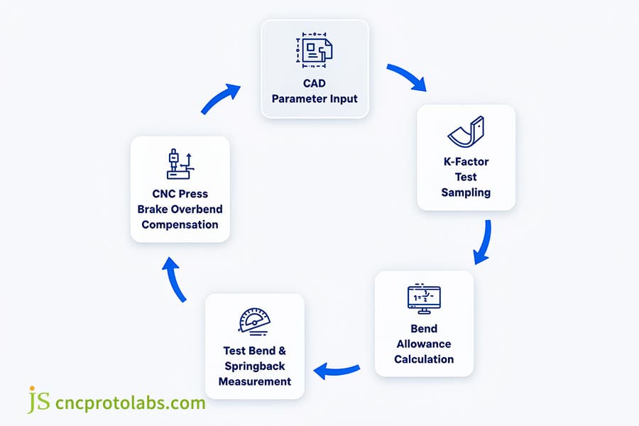
Figure 3: The engineering closed-loop flowchart of CAD drawing parameter input → K-Factor test sampling calibration → bending compensation calculation → test bending rebound angle → CNC bending machine punch stroke over bending compensation.
FAQ
Q1: How to calculate k-factor in sheet metal bending?
Calculate K by running a test bend in reverse. Prepare a coupon of known thickness T and bend it 90° at room temperature. Measure the two outer flange lengths and the inside radius R, derive the true bend allowance BA from the measured total length, then solve: K = (BA / (90 × (π/180)) − R) / T.
Q2: Why does sheet metal springback occur after bending?
Bending produces elastic and plastic deformation at the same time. Material well away from the neutral layer yields and flows plastically, but a thin band of metal near the neutral layer never reaches yield — it only deforms elastically. When the punch retracts, that stored elastic strain is released and the flange opens back up. That opening is springback.
Q3: How do you compensate for springback in air bending?
Set the bend angle deeper than the target. The punch drives slightly past the reference angle — for example, bending a 90° part to 88° — so the material springs back **by** about 2° and lands on the nominal 90°. Use an 86°–87° punch with a V = 8T die opening to keep the result repeatable.
Q4: What k-factor should be used for aluminum bending?
The K-factor of aluminum alloys depends on their annealing state and alloy composition. For soft-annealed aluminium such as 1100-O or 5052-H32, use K = 0.40–0.43. For precipitation-hardened alloys such as 6061-T6, use K = 0.38–0.42 — their higher flow resistance increases internal compression and pulls the neutral axis inward.
Q5: Can bend deduction be a negative number?
Bend deduction is positive in most cases. But in large-radius bending — where the inside radius R exceeds about five times the sheet thickness T — the neutral-layer arc becomes longer than the distance between the two virtual tangent apexes. The summed outside dimensions then fall short of the true flat length, and the calculated BD comes out negative.
Summary
Simply put, these three values form one closed loop. The K-factor sets where the neutral layer sits, bend allowance turns that into a flat blank size, and springback compensation determines the final forming accuracy through die selection and bottom-dead-centre control. Get any one of them wrong and the other two inherit the error. The close integration of these three factors is the cornerstone for ensuring no assembly interference in various precision metal sheet metal parts. When discussing actual factory production and bending forming control, custom sheet metal bending services can be used to translate theory into stable mass production.
Next step: read CNC Sheet Metal Bending DFM Guide: How to Design Accurate Flanges for tool selection and bend-sequence rules, then confirm your K-value on a test coupon before releasing production blanks.
Disclaimer
The contents of this page are for informational purposes only. For JS Precision Services, there are no representations or warranties, express or implied, as to the accuracy, completeness, or validity of the information. It is the buyer's responsibility to identify specific technical requirements and request a formal parts quotation. Please contact us for more information.
Resource

