 English



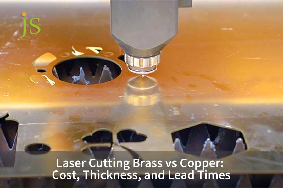

Laser cutting brass vs copper presents distinct manufacturing trade-offs in per-part machining cost, maximum thickness capability, and overall production lead times. Brass (C26000/C36000) cuts faster, reaches up to 12 mm, and ships in 2–4 days; pure copper (C11000) reflects over 95% of the beam, conducts heat at 400 W/m·K, is limited to 8 mm, ships in 5–9 days, and costs 35%–55% more. The choice comes down to balancing conductivity requirements against budget.
Core Takeaway Table: Laser Cutting Brass vs Copper
Material definitions: C11000 is electrolytic tough pitch (ETP) copper, ≥99.9% pure, with a thermal conductivity of about 400 W/m·K and ~100% IACS electrical conductivity. C26000 (cartridge brass, 70% Cu / 30% Zn) and C36000 (free-cutting brass, ~61.5% Cu / 3% Pb) have roughly 28% IACS conductivity but machine and cut far more easily.
|
Evaluation Dimension |
Brass (C26000/C36000) |
Copper (C11000) |
Key Technical Parameters & Physical Drivers |
|---|---|---|---|
|
Cost |
Baseline (1.0x) |
+35%–55% |
1.064 μm absorptivity: Brass 15% vs Copper 5%; Feed rate: 8.5 vs 5.5 m/min (3 mm) |
|
Thickness |
Max 12 mm (±0.10 mm) |
Max 8 mm (±0.12 mm) |
Thermal conductivity: Cu 400 W/m·K vs Brass 115 W/m·K; Taper >0.15 mm beyond limits |
|
Lead Times |
2–4 days (prototype/batch) |
5–9 days |
Piercing time: Cu 0.35–1.2 s vs Brass 0.1–0.3 s; Leapfrog toolpath mandatory for Cu |
Pure copper's 5% absorptivity and 400 W/m·K thermal conductivity directly explain three outcomes: processing cost is more than 35% higher, the effective thickness limit is 8 mm, and lead time runs about 40% longer than for brass.
According to ASTM B36/B36M-18 (Standard Specification for Brass Plate, Sheet, Strip, and Rolled Bar) and ASTM B152/B152M (Standard Specification for Copper Sheet, Strip, Plate, and Rolled Bar), the chemical composition and dimensional tolerances of C26000 brass and C11000 copper sheet are defined, supporting the material and thickness data in this table.
What Is the Difference Between Laser Cutting Brass vs Copper?
The primary difference in laser cutting brass vs copper comes down to beam reflection and how fast each alloy dissipates heat from the cut kerf. Brass contains zinc, which reduces its thermal conductivity to 115 W/m·K and allows it to absorb roughly 15% of fiber laser light at room temperature to sustain a stable cutting melt pool. Pure copper reflects more than 95% of the laser beam and draws heat away at 400 W/m·K. This rapid heat dissipation makes copper far more susceptible to edge dross, requiring specialized pulse controls to prevent catastrophic back-reflection damage to optical cutting heads.
Solid-state reflection and molten pool absorption mechanism
- In the solid state, pure copper reflects over 95% of the light from a 1.064 μm fiber laser. Only after a molten pool forms does its absorptivity rise above 15%. In addition, zinc in brass boils at 907°C, producing a micro-explosion effect that helps the high-pressure nitrogen jet expel slag from the kerf.
- Brass (C26000) melts between 915°C and 955°C and flows smoothly, whereas pure copper melts at a much higher temperature (1,083°C) and is highly viscous when molten because of strong surface adhesion. As a result, copper often leaves solidified slag on the bottom edge of the cut.
Optical protection and equipment safety
Any shop cutting copper should use a cutting head fitted with a back-reflection isolator that blocks abnormal reflections within milliseconds, preventing burnout of the fiber laser source.
On the machine side, that isolator is paired with real-time power feedback that compensates for batch-to-batch variation in sheet reflectivity and thickness, keeping the kerf width stable across an entire nest.
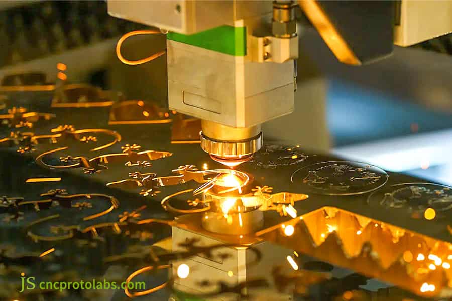
Figure 1: Laser cutting brass and copper sheet with sparks.
What Are the Maximum Thickness and Tolerance Limits for Brass and Copper?
Thickness and cutting tolerances depend directly on available laser wattage and continuous melt-pool control during the cut. With an industrial 12 kW fiber laser, laser cutting brass achieves burr-free edges up to 12 mm while holding tolerances within ±0.10 mm. In contrast, copper laser cutting thickness reliably maxes out at 8 mm for precision electrical assemblies. Cutting copper past 8 mm causes the bottom of the kerf to freeze prematurely, resulting in cutting in an edge taper over 0.15 mm and heavy dross that requires costly secondary machining.
Performance limits of 6 kW and 12 kW laser machines
- Brass holds a stable ±0.05 mm tolerance on thin 0.5–3.0 mm sheet, and 12 mm plate meets the ISO 9013 Range 2 perpendicularity requirement. Pure copper holds ±0.05 mm only up to 4.0 mm.
- Between 6.0 mm and 8.0 mm, the copper kerf widens to 0.35 mm and the single-side bevel taper on the cut face becomes significant. Beyond 8.0 mm, the piercing blowout rate rises sharply, so we do not recommend laser cutting at that thickness.
Alternative Processes for Ultra-Thick Plates (Beyond 8 mm)
- When copper exceeds 8.0 mm and the mating face must stay perpendicular, switch to waterjet cutting or CNC milling. Relying on laser at that thickness drives scrap rates out of control.
- In JS Precision's 2025 conductive busbar project, laser-cut copper 8 mm and thicker showed a taper deviation of up to 18%, versus roughly ±0.10 mm achievable with waterjet cutting.
|
Material Grade |
Thickness (mm) |
Recommended Power (kW) |
Cutting Speed (m/min) |
Dimensional Tolerance (mm) |
Edge Taper / Perpendicularity |
|---|---|---|---|---|---|
|
Brass C26000 |
0.5–3.0 |
6 |
8.5 |
±0.05 |
ISO 9013 Class 2 |
|
Brass C26000 |
4.0–12.0 |
12 |
6.0 |
±0.10 |
ISO 9013 Class 2 |
|
Copper C11000 |
0.5–3.0 |
6 |
5.5 |
±0.05 |
ISO 9013 Class 3 |
|
Copper C11000 |
4.0–8.0 |
12 |
3.8 |
±0.12 |
Taper ≤0.15 mm |
According to ISO 9013:2017, Thermal cutting — Classification of thermal cuts — Geometrical product specification and quality tolerances defines the 2-class perpendicularity standard referenced for 12 mm brass cutting.
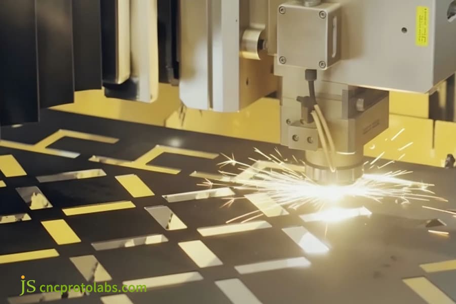
Figure 2: Laser cutting precise shapes on metal sheet.
How Do Cutting Speeds and Materials Drive Brass vs Copper Laser Cutting Cost?
The brass vs copper laser cutting cost variance is driven by raw material market pricing, cut feeds, and auxiliary gas consumption rates. Pure copper raw sheet carries a 20% to 30% price premium over standard yellow brass. On the cutting table, pure copper processes roughly 35% slower than brass of identical thickness to prevent bottom dross formation. Combined with continuous 2.2 MPa high-pressure nitrogen consumption, custom laser cutting service quotes for copper parts average 35% to 55% higher than brass speed parts.
Quotation Calculation Formula and Work Hour Breakdown
Total quote = Net raw material cost + Laser machine time cost + Auxiliary gas consumption cost + Post-processing deburring and polishing time.
For batch production of 3.0 mm thick parts, the feed speed for brass is 8.5 m/min, whereas for pure copper it's only 5.5 m/min, which accounts for more than 50% extra machine time.
Piercing holes in pure copper requires multi-pulse drilling, so each hole takes 3 to 4 times longer than in brass — a major machine-time cost on parts with dense hole patterns.
Gas consumption and lens depreciation
Once the cost of 2.2 MPa high-purity nitrogen (consumed at 45–55 m³/h) and the frequent replacement of protective cover slides are included, finished copper parts carry a 35%–55% price premium over brass.
JS Precision's 2025 cost analysis found that piercing accounted for 15% of total processing time. When a single copper part contains more than 200 holes, that share rises to 40%.
|
Cost Component |
Brass (per part) |
Copper (per part) |
Cost Difference |
Physical Driver |
|---|---|---|---|---|
|
Raw Material |
$1.00 |
$1.25 |
+25% |
Copper sheet premium 20%–30% |
|
Machine Time |
$0.80 |
$1.20 |
+50% |
Feed rate 8.5 vs 5.5 m/min |
|
Assist Gas |
$0.30 |
$0.55 |
+83% |
2.2 MPa N₂ consumption 45–55 m³/h |
|
Deburring |
$0.10 |
$0.20 |
+100% |
Manual nylon wheel finishing |
|
Total |
$2.20 |
$3.20 |
+45% |
Systemic cost driver |
The cost differentials above come from JS Precision's 2025 internal cost model for 3.0 mm C26000 brass and C11000 copper parts, with gas consumption measured on our 12 kW fiber laser cells. Edge quality classes referenced elsewhere in this article follow ISO 9013, which classifies thermal-cut geometry independently of cost — no external standard is cited for the price multipliers themselves.
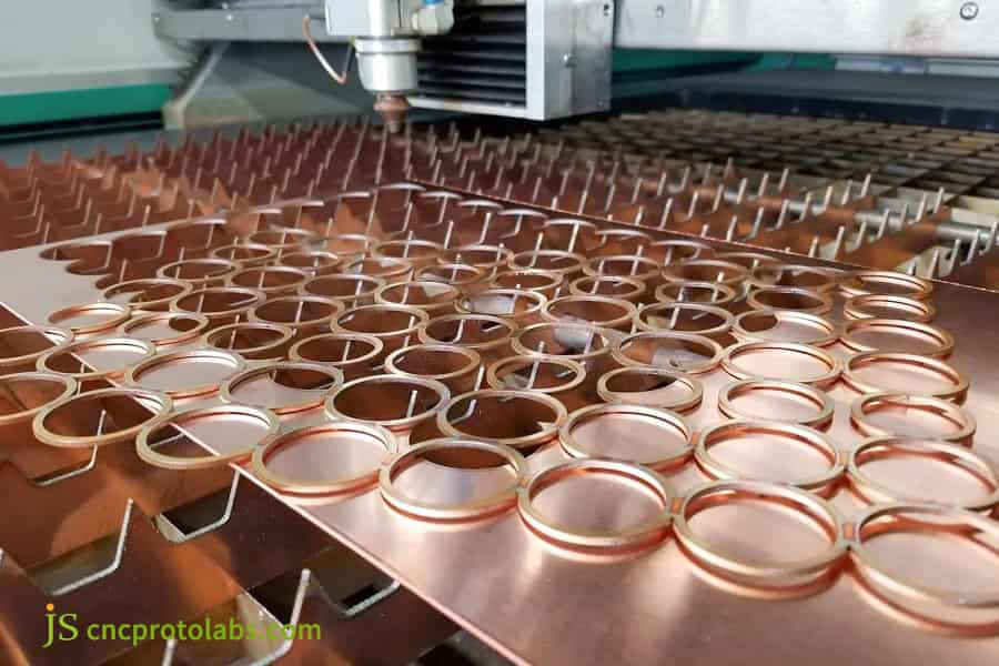
Figure 3: Laser cutting numerous copper ring parts.

How Do Auxiliary Gases Impact Cutting Thickness and Processing Cost?
Auxiliary gas selection directly governs maximum cut thickness, edge oxidation, and processing cost in laser cutting reflective metals. Laser cutting brass universally relies on 1.6 to 2.0 MPa high-pressure nitrogen, producing oxide-free, weld-ready edges that eliminate secondary deburring costs. For pure copper over 4.0 mm, manufacturers choose between 2.2 MPa high-pressure nitrogen to preserve electrical conductivity at a higher gas cost, or 0.8 to 1.2 MPa oxygen to penetrate thicker plates faster while accepting post-cut oxide removal expenses.
Economic efficiency of nitrogen cutting of brass
For brass, 99.999% pure nitrogen at 1.6–2.0 MPa cuts cleanly through 12 mm plate while keeping the metal surface color unchanged. Because no mechanical polishing is needed afterward, post-processing labor cost drops sharply.
Eliminating pickling and polishing also means brass parts can go straight to welding, removing the queuing time those secondary steps would otherwise add.
Electrical conductivity and cost tradeoffs for pure copper gas selection
- Conductive busbars for new energy applications must be cut with 2.2 MPa ultra-high-pressure nitrogen. This consumes a large volume of gas and carries a high setup cost, and it caps thickness at 8 mm. For general structural parts, switching to 0.8–1.2 MPa oxygen raises cutting speed substantially through the exothermic oxidation reaction and pushes penetration depth beyond 10 mm.
- During oxygen gas cutting, there is a formation of a 20–40 μm black oxide film on the cut surface. The customer must determine at the drawing stage the need for acid-washing additional expenses as the second step for oxide removal.
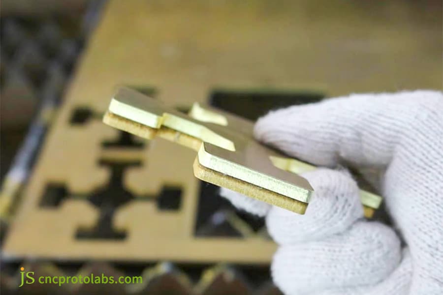
Figure 4: Hand holding cut brass sheet metal parts.
What Are the Lead Time Differences in Brass and Copper Laser Cutting?
Lead-time variations in a custom laser cutting service for brass and copper stem from raw material readiness, surface preparation, and specialized deburring workflows. Standard brass sheets (C26000/C36000) are widely stocked in common gauges, allowing rapid-prototyping orders to ship in 2 to 4 business days with automated cutting nesting. Pure copper components require 5 to 9 business days because raw sheets require chemical deoxidation, slower leapfrog cutting toolpaths to prevent thermal warping, and careful manual deburring.
Brass workshop turnover efficiency
- We maintain stock for brass sheets at our factory of 0.5–10 mm thickness. Laser cutting takes care of removing the burrs before the sheets are sent for vibratory grinding. The products get packed and shipped after passing the quality control check.
- The sampling process takes 2–3 days and bulk ordering 4–6 days. Material utilization can be increased through the use of automatically-nested software, thereby minimizing production time per piece to a greater extent.
Time consumption of pure copper pretreatment and skip-step cutting
- Copper oxidizes and discolors easily, so degreasing and a light acid wash are added before cutting to ensure a consistent surface finish and prevent localized arcing at the pierce point. A leapfrog (skip-step) toolpath must then be used; because of the frequent long idle traverses it requires, cycle time for a single sheet increases by 20%–30%.
- Pure copper is very soft, so deburring must be done manually by skilled operators using a nylon fiber wheel. These steps are the main reason the lead time for copper is 5–9 days.
|
Production Stage |
Brass Lead Time (days) |
Copper Lead Time (days) |
Copper Delay Driver |
|---|---|---|---|
|
Raw Material Prep |
0.5 |
1.0 |
Chemical deoxidation required |
|
Nesting & Cutting |
1.0 |
2.0 |
Leapfrog toolpath + slower feed |
|
Deburring |
0.5 |
1.5 |
Manual nylon wheel finishing |
|
QC & Packaging |
0.5 |
0.5 |
Full inspection for dross |
|
Total |
2–4 |
5–9 |
Extended by 3–5 days |
According to ISO 9001:2015, Quality management systems — Requirements provides the audit framework for production lead-time tracking and process-control documentation in precision manufacturing.
How Do You Maintain Flatness and Tolerances in Thin Brass and Copper?
Maintaining flatness and dimensional tolerances in laser cutting thin brass vs copper requires distinct heat-dispersion strategies and mechanical sheet-retention methods. Brass sheets between 0.5 mm and 2.0 mm maintain planar stability relatively well, achieving flatness within 0.2 mm/m under standard high-pressure nitrogen parameters. Pure copper sheets of identical gauge are far more susceptible to severe thermal buckling due to rapid heat dissipation and low yield strength. A professional sheet metal laser cutting service counters this distortion by deploying scattered leapfrog toolpaths, calibrated micro-joints, and optical sensors that prevent thermal runaway.
Mechanism of Thin Plate Thermal Warping Control
- Brass has good strength against deformation; the residual internal stress produced by machining and firing will not lead to an overall warp, and flatness can be easily maintained to 0.2 mm/m.
- Pure copper is quite soft and heat-conducting. When a part of a sheet is heated up locally, the whole plate becomes very susceptible to wavy thermal buckling.
This physical occurrence directly leads to a conclusion that in thin plate processing, a scattered skip-step cutting approach must be used to limit deformation from heat accumulation.
Three methods of workshop quality control
- In CAD/CAM nesting continuous machining process is totally replaced by a heat island skip-step machining that allows dispersal of heat. To lock the part's edge and this way prevent curling of a hot part from scraping the tool a 0.2–0.3 mm micro joint will be added on the part edge after cutting. The light spot grinding will make it smooth when the part is removed.
- Stabilization of laser output in real time helps prevent heat runaway. For long, thin plate parts the gaps between the perforations must be at least two times the plate thickness. This will ensure no secondary manually flattening is needed.
JS Precision Case Study: Eliminating Slag on Custom Laser-Cut Copper Busbars
JS Precision developed an optimized procedure for 5 mm C11000 copper electrical busbars to eliminate heavy dross and dimensional taper under tight schedules. An automotive customer required 15,000 units of custom laser copper parts with a hole tolerance of ±0.05 mm and zero dross for automated cutting ultrasonic welding. By switching from oxygen cutting to a 12 kW ring-mode fiber laser with 2.2 MPa nitrogen, JS Precision eliminated secondary edge milling and delivered the completed order within 6 business days.
The Customer's Challenge
The original supplier of the customer used a 6 kW laser machine in conjunction with oxygen cutting to cut a 5 mm C11000 pure copper busbar, with a hard slag thickness of up to 0.2 mm attached to the edge and a unilateral taper of 0.12 mm on the end face, resulting in a high virtual welding rate of 18% in subsequent ultrasonic lap welding and facing the risk of delivery default.
The supplier tried a faster cutting rate of 4.5 m/min and as a result, the copper plate internal stress was abruptly released and led to the whole plate warping by 3 mm. The anti-collision module of the cutter suddenly braked and broke the nozzle and ceramic ring that cost the supplier over $1,200.
JS Precision Solution
- We switched to a 12 kW ring-mode spot laser with 2.2 MPa high-purity nitrogen (99.999%) as the assist gas. This improves the fluidity of the molten copper: the outer ring beam preheats while the center beam delivers deep penetration. Combined with CAM parameter optimization and a three-stage ramp low-frequency piercing technique, single-hole piercing time dropped from 1.2 s to 0.35 s without spatter.
- We reordered the skip-cutting path and added 0.3 mm micro-tabs inside the part contour to prevent deformation from thermal stress release. Cutting speed was held at a stable 3.8 m/min, and a localized water-mist cooling system was added. This practice is now a shop-floor SOP.
What Failed: Lessons Learned From the Trial Run
During the first 50-piece trial run, we raised the cutting speed to 4.5 m/min to accelerate delivery. Taper was initially acceptable, but the release of internal stress caused the entire sheet to warp suddenly by about 3 mm. The anti-collision module then braked, damaging the nozzle and ceramic ring at a cost of over $1,200.
The lesson is clear: for highly reflective metals such as copper, numerical compensation alone cannot recover cut quality once large deformation has occurred. Cutting speed must stay below the material's thermal-stress threshold, and micro-tabs plus water-mist cooling are mandatory.
Final result
- Dross thickness at the cut edge was reduced to below 0.02 mm, making the parts ship-ready without grinding.
- End-face taper was reduced to 0.03 mm, with dimensional deviation held at ±0.04 mm.
- First-pass yield of ultrasonic welding rose to 99.7%, saving the customer 32% on secondary deburring costs.
- All 15,000 pieces were fully inspected and delivered within 6 working days. The method has been formally adopted as the standard operating procedure (SOP) for laser metal cutting at JS Precision.
Want to replicate this successful pure copper busbar case? Contact JS Precision engineers now to get the same 12 kW annular spot zero-slag solution and make your parts right the first time!
FAQs
Q1: Why is laser cutting pure copper significantly more expensive than brass?
Pure copper has a room temperature reflectivity exceeding 92%, necessitating a reduced cutting speed to prevent damage; the cutting speed is 30%–40% slower than that of brass. Combined with the consumption of 2.2 MPa high-pressure nitrogen and a 20%–30% premium in raw material costs, the overall machine time and auxiliary material costs increase the quoted price by 35%–55%.
Q2: What causes blackened cut edges and excessive dross on laser-cut brass parts?
Blackened brass edges are usually caused by low nitrogen purity or insufficient pressure. Brass requires 99.999% nitrogen at 1.6–2.0 MPa to expel slag and shield the cut zone from oxygen. If pressure is too low, zinc oxidizes and blackens, leaving hard deposits on the underside of the cut.
Q3: What is the maximum reliable thickness limit for laser cutting copper in volume production?
For large-scale production, the reliable upper limit for pure copper laser cutting with a 12 kW fiber laser is 8 mm. Going over that limit will trigger the underlying layer to cool and solidify rapidly due to heat conduction, which will result in the severe deposition of slag and the taper exceeding 0.15 mm. In those cases, we recommend switching to waterjet cutting or CNC milling.
Q4: What critical DFM guidelines should engineers follow when designing laser-cut brass and copper parts?
Keep the inner hole diameter at ≥1.0× the sheet thickness (0.8× is achievable only on thin gauge); keep the distance from hole edge to part edge at >1.5× the sheet thickness — 2× for thin, slender parts — to prevent heat distortion. For copper thicker than 4 mm, reserve a 0.1 mm taper compensation allowance on the end face.
Q5: Can JS Precision handle rapid prototyping or low-volume custom laser cutting orders for copper busbars?
JS Precision stocks C26000 brass and C11000 copper sheet in common gauges, so we can handle small-batch prototyping without material lead time. The design team guarantees a Design for Manufacturing (DFM) review in two hours after getting drawings, while a small-batch prototype can be delivered as fast as 48–72 hours from the time drawings were delivered to JS Precision including cutting, deburring, and inspection.
Q6: How does laser cutting compare to Wire EDM for processing copper parts?
Laser cutting is faster and more economical, making it the preferred choice for 0.5–8 mm copper plate in volume. For plates over 10 mm, or where tolerances approach ±0.005 mm, wire EDM still delivers superior straightness and precision.
Q7: Should engineers choose high-pressure nitrogen or oxygen assist gas for cutting thick copper plates?
For electrically conductive parts, 2.2 MPa high-pressure nitrogen must be selected, as the cut surface is free of oxidation and has excellent conductivity; for structural parts with a plate thickness of more than 4 mm and subsequent machining, 0.8–1.2 MPa oxygen can be selected to speed up the cutting speed, but a dark oxide scale will be attached to the surface.
Q8: What exact details are required to get an accurate custom laser cutting quote from JS Precision?
Send the unfolded engineering drawings (DXF/DWG/STEP) specifying also material grade (C11000 or C26000), sheet thickness, edge tolerances, and batch number. Our engineering team will generate a formal quotation within 2 hours.
Summary
The choice between laser-cut brass and pure copper essentially boils down to a trade-off between optical and physical properties, maximum thickness, end-face tolerances, and production budget. Brass offers high cutting speed, a thickness of up to 12 mm, and eliminates the need for secondary polishing, making it a cost-effective option. Pure copper, due to its extremely high thermal conductivity and strong reflectivity, has a slag-free cutting limit of 8 mm and requires advanced laser spot modulation and 2.2 MPa nitrogen gas. Clearly balancing conductivity requirements and taper tolerances in the initial design phase can avoid unnecessary manufacturing costs.
JS Precision is equipped with a 12 kW ring-spot fiber laser system, featuring millisecond-level back-reflection protection sensors and ultra-high-pressure nitrogen piping. Upload your DXF or STEP drawings now and receive an authoritative DFM assessment and itemized quote within 2 hours, ensuring you get the job right the first time with challenging brass and pure copper parts!
Disclaimer
The contents of this page are for informational purposes only. For JS Precision Services, there are no representations or warranties, express or implied, as to the accuracy, completeness, or validity of the information. It is the buyer's responsibility to identify specific technical requirements and request a formal parts quotation. Please contact us for more information.
Resource

