 English



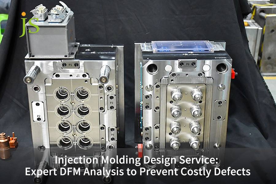

Injection molding design service is an early phase manufacturing feasibility review of plastic part CAD models before the first steel cutting. It is performed to check wall thickness drafts location and size of gates and other mold flow aspects with a view to avoiding tooling problems. JS Precision DFM analysis service detects possible warping, depressions, and air trapping through the mold rework cost reduction up to 85% and the time to market reduction by 2 to 3 weeks.
Overview of Injection Molding DFM Service Core Information
| DFM Focus Area | Common Defect | JS Precision Standard | Cost & Quality Impact |
| Wall thickness | Warpage, sink, voids | Nominal ±10%, 3:1 transition ratio | 18% shorter cycle, zero structural voids |
| Draft angle | Scuff, drag, ejection lock | Base ≥1.5°, +1° per 0.025mm VDI 24 texture | Eliminates surface damage, extends mold life |
| Ribs & bosses | Base sink, cosmetic flaw | Rib ≤60% wall, root radius R=0.5t | Zero sink on Class-A surfaces |
| Gate & runner | Weld line, air trap, shear | Shear rate <100,000 s⁻¹, sequential valve gate | +35% mechanical strength & pressure resistance |
Key Takeaways
- Detect and Remove Issues: One approach to save on mold rework is early DFM for plastic injection molding.
- The Power of Rules: Ensuring an even wall thickness, beyond a reasonable minimum 1.5° draft angle, will prevent dimensional instability and facilitate easy part ejection.
- Simulations: Perform professional injection molding manufacturability assessment and eliminate high stress zone weld lines through filling simulation.
- Work with a Manufacturer from the Start: Working with a custom precision injection molding service vendor like JS Precision at the early stages of design might reduce project lead times by 14 days.
Why Trust JS Precision’s Injection Molding Design Service To Avoid Mold Rework?
According to market research, 70% of manufacturing costs are set during the product design stage. In a real-life development project for a car sensors PPS+40% GFR housing product, the first few trials with the mold led to 0.45mm warpage. A single CNC mold fix ranged in cost from $2,500 to $8,000 and the project schedule was pushed by 10-21 days.
By putting the DFM at the front of the design process, we have lowered the warpage down to 0.015mm, cut the cycle time from 42 seconds to 29 seconds, and raised the pass rate (99.8%).
The standard ISO 294-3:2020 specifies very clearly that injection-molded specimens shall be prepared per carefully controlled processing conditions, and the main process parameters (holding pressure, mold temperature, shear rate) shall be recorded and checked.
To fully meet these regulations and the customer needs, JS Precision's engineering team calculates heat transfer and fluid dynamics during CAD. We deliver a DFM report that lists the top 22 factors in molding: for example, we optimize wall thickness, runner design, and clamping force parameters.
Want to systematically master DFM optimization parameters and cost-avoidance strategies? Download JS Precision's Injection Molding DFM Defect Prevention White Paper to access wall-thickness transition templates and ejection force calculation formulas.
Why Is Injection Molding Design Service Critical Before Mold Fabrication?
Injection molding design service identify flow bottlenecks and interference risks before mold fabrication, reducing mold modification costs by 85%. Upfront analysis allows for the early elimination of potential issues-such as sink marks, warpage, flash, and demolding difficulties-that might otherwise arise during mold trials.
Cost of going through mold making without DFM review:
- Cost for each modification of the mold: 2,500-8,000 given complexity.
- Delay delivery of the product: each change of the mold will require 10-21 days, seriously cutting down the product launch time.
- Cumulative risk: 70% of total manufacturing cost is determined during the design stage. Marginal benefit of each subsequent change of design quickly decreases.
JS Precision's 22 DFM checklist items:
- Geometric dimensioning: Wall thickness distribution, draft angle, rib ratio, and undercuts.
- Process settings: Position of gates, runner balance, clamping force, and holding pressure profiles.
- Material characteristics: Shrinkage anisotropy, glass fiber orientation, and post-shrinkage compensation.
- Inspection requirements: Critical dimension tolerance area, coordinate measuring machine (CMM) inspection datum point, and assembly clearance.
Multiple-level tolerance setting:
- Surfaces without mating: General tolerances of the 0.1mm range are applied without tightening, to avoid unnecessary tight tolerance requirements.
- Normally mating surface: Follow the ISO 20457 TG6 guideline.
- Sealing/bearing surfaces of high importance: Tolerance set to control at ISO 20457 TG4 level of precision.
In the field of injection molding defect prevention, setting multiple levels of tolerances is one of the major cost-saving techniques. By assigning a level of precision suited for the feature rather than aiming to attain the tightest possible tolerances everywhere, customers are able to reduce the mold machining costs by 20% to 35%.
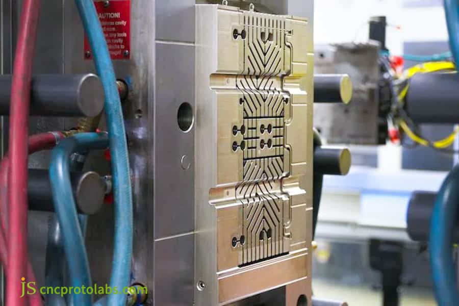
Figure 1: Industrial injection mold with cooling channels and ejector pins.
How Does Plastic Part DFM Optimization Prevent Warpage and Sink Marks?
Plastic part DFM optimization mandates uniform wall thickness and gradual transitions, keeping sudden changes to minimal ±10% to avoid problems such as warpe and sink marks. We check material properties and geometry standards against each other to confirm that internal stress distribution during the melting-solidifying process is even.
Strict Control Standards for Wall Thickness Transitions
- Gradual Transition Ratio: The adjacent wall thickness transition ratio shall be less than 3:1.
- Ramp Length: The transition ramp length shall be more than three times the wall thickness difference.
- Local Upper Limit: Should a localized area exceed by more than 120% the standard wall thickness, the core slow cooling causes inward tensile stress resulting in the surface sink marks.
Recommended Wall Thickness and Shrinkage Rates for Common Engineering Plastics
| Material | Recommended Wall (mm) | Shrinkage Rate | Draft Angle (Base) | Typical Application |
| ABS | 2.0–3.5 | 0.4%–0.7% | 1.0° smooth / 1.5°+ textured | Consumer electronics housings |
| PC | 2.4–3.8 | 0.5%–0.7% | 1.5° smooth / 2°+ textured | Optical & transparent parts |
| PA66+30%GF | 1.5–2.8 | 0.3%–0.8% (flow) / 0.7%–1.2% (cross-flow) | 1.5°+ | Automotive structural parts |
| POM | 1.5–3.0 | 1.8%–2.5% | 1.5°+ | Precision gears, bearings |
| PPS+40%GF | 1.0–2.5 | 0.2%–0.4% | 1.5°+ | Sensor housings, high-temp parts |
Optimization Benefits
- Shortening of Cycle Time: Through optimized wall thickness design, the injection molding cycle time is estimated to decrease by 15% to 22%.
- The Elimination of Fault: This completely tackles sink mark issues while enhancing part surface quality.
- Material Cost Saving: Equal distribution of wall thickness minimizes hot spot areas in a localized manner and lessens the amount of wasted materials.
The core value of DFM analysis service lies in data-driven decision-making. Our professional team at JS Precision delivers sink mark risk evaluation within 30 minutes, allowing changes to be made and preventing the need of going into the mold making process.
Submit your design to receive a wall thickness optimization analysis from JS Precision and have your part evaluated for sink mark risks within 30 minutes.

Figure 2: Assortment of blue and white precision plastic parts.
Why Does Proper Draft Angle Design Prevent Surface Scuffs and Ejection Failure?
In DFM, applying a draft angle of at least 1.5° minimizes mold release friction, preventing drag marks and deformation. The minimum necessary draft angle is determined for each vertical side by calculating the mold release resistance.
Engineering formula for ejection force:
Feject = E × α × ΔT × A × μ
Variable definitions:
- E: Material modulus of elasticity (MPa)
- α: Coefficient of thermal expansion (1/℃)
- ΔT: Temperature difference (℃)
- A: Gripping area (mm²)
- μ: Coefficient of friction
ISO 1:2016 stipulates: The standard reference temperature for geometric and dimensional specifications is 20℃.
In order to strictly implement this standard, JS Precision calculates all draft angles and demolding forces for DFM for plastic injection molding at a benchmark of 20℃, ensuring that the slope values marked in CAD are consistent with the calculated clamping force under actual injection molding conditions, and preventing demolding failure caused by temperature benchmark confusion.
Draft angle classification standards:
- Polished surfaces: the minimum draft should be 1.0°, to be safe, 1.5°-2.0° is a good choice for deep cavity parts.
- Surface with texture (VDI 3400 / Mold-Tech): For every 0.025mm increase in texture depth, the draft angle must go up by 1°.
- Core surfaces (inner side of flutes): A minimum of 0.5°, 1.0° is best.
- Shut off surfaces: At least 3.0° should be used to prevent the wear on the tools before time.
CAD review items:
- Mark of no-draft area: Spot in the CAD model all the areas where there is no draft or there is a risk of reverse drafting.
- Deep Rib Mold Release Check: The minimum side draft angle should be 0.5° for 20mm deep ribs to have a clean demolding.
- Texture Depth Match: A 3.0° draft angle is applied by default before the texture is finalized, this prevents flash due to the later depth increase caused by texturing.
In the evaluation of injection molding manufacturability, draft angle is the first hurdle that affects the success rate of demolding. A simple 1 ° slope adjustment can reduce the ejection damage rate from 5% to below 0.1%.
Contact JS Precision experts for a free draft angle analysis report to ensure that every vertical surface in your CAD model meets the requirements for safe demolding.
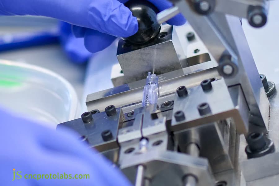
Figure 3: Worker assembling clear plastic parts on machinery.
How Does Mold Flow Simulation Predict and Eliminate Weld Lines and Air Traps?
Mold flow simulation during DFM is accurate at predicting melt impingement and air traps. Besides, by optimizing the gate and venting setups, it improves structural integrity. The advanced simulation capability of Moldflow software brings down tensile strength loss of weld line segments from as high as 50% down to below 5%.
Hot Runner Sequential Valve Gating
- Gate Opening Sequence: The order in which gates are opened is modified to direct the melt front to intersect away from load-bearing areas.
- Weld Line Relocation: Welds are moved to areas that are either hidden to the user or where structural loads are minimum.
- Dead Zone Elimination: This removes any convergence dead zones altogether to avoid burning or short shots that might be a result of gas trapping.
Micron-level Venting Slot Design
- Venting Slot Depth: 0.015mm to 0.025mm.
- Placement: Located at the final melt convergence points.
- Venting Efficiency: Ensures rapid gas evacuation without causing flash.
Mold Flow Simulation Output List
- Fill Balance Map: Adjusts filling time disparities between cavities to less than 0.02 seconds.
- Weld Line Strength Map: Locates each weld line's site of strength reduction and shows it by percentage.
- Air Trap Prediction Map: Indicates all of the potential air trap spots.
- Warpage Deformation Map: Forecasts deformation for X, Y, and Z.
The key to injection molding defect prevention lies in simulation first. JS Precision's injection molding DFM service offers the weld line angle as well as melt front temperature difference as the priorities of mold flow analysis, a convergence angle of more than 135°, and a temperature difference of less than 5℃ being the minimum standard we have for avoiding strength weakness.
Submit your 3D CAD drawings to have the JS Precision team conduct a mold flow analysis, and receive a simulation report along with gate optimization recommendations within 48 hours.
How to Balance Structural Strength and Flawless Surface in Rib and Boss Design?
Optimizing rib thickness to below 60% of the main wall thickness maintains rigidity while eliminating sink marks. JS Precision adheres to the following geometric rules to ensure structural integrity without compromising the appearance of visible surfaces.
Rib Geometric Parameters
| Parameter | JS Precision Standard | Physical Rationale |
| Rib base thickness | 50%–60% of main wall (Tw) | Exceeding 60% → sink mark on opposite surface |
| Rib height | ≤ 3 × Tw | Taller → filling resistance & cooling differential |
| Root radius (R) | 0.25 Tw ≤ R ≤ 0.4 Tw | Reduces stress concentration, prevents cracking |
| Rib spacing | ≥ 2 × Tw (center-to-center) | Allows cooling water access, prevents thermal bridging |
| Rib draft | 0.5°–1.0° per side | Ensures clean ejection of tall, thin features |
Boss Geometric Controls
- Outer Diameter: Make it double the inner diameter so that the hoop stress can be resisted adequately.
- Height Limit: Breaking the bar beyond three times the diameter of the outer circle is not allowed, very tall bosses must be provided with triangular gussets.
- Root Gussets: Four gussets at 90° intervals around the wall acting as reinforcements to the main wall and preventing it from bursting when the self-tapping screw is inserted.
- Inner Wall Thickness: Kept between 50% and 60% of the thickness of the main wall.
Performance Comparison: Before vs. After
| Metric | Before Optimization | After DFM Optimization |
| Sink mark on Class-A surface | Visible 0.15mm depression | Zero depression |
| Structural stiffness | Baseline | 80% stiffness at 40% weight |
| Rib-to-rib intersection volume | 3.5 × nominal wall | 1.0 × nominal wall (cored out) |
Plastic part DFM optimization in this case mainly revolves around a couple of changes - instead of thick walls, use ribs and for sharp corners, turn to the use of fillet radii that soften the angles. JS Precision's custom precision injection molding service will check the thickness ratio and fillet radius of each rib one by one when reviewing your CAD to ensure that there will be no shrinkage caused by local excessive thickness.
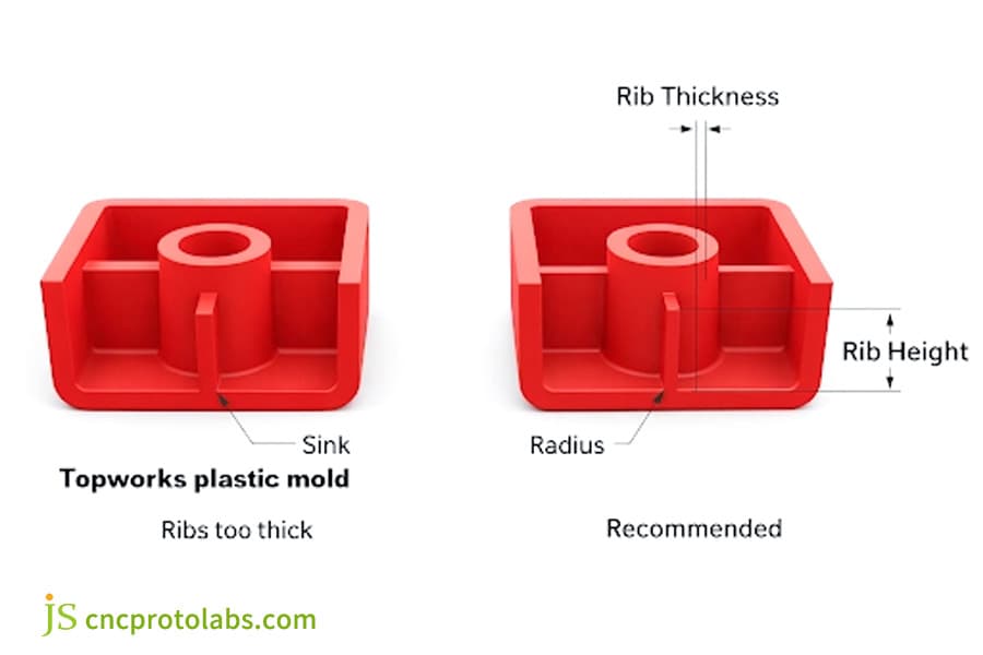
Figure 4: Diagram showing recommended vs thick rib design.
How Do Smart Undercut and Parting Line Designs Reduce Tooling Cost and Complexity?
Smart undercutting plans eliminate redundant side-action cores through the use of pass-through and shut-off structures, thereby decreasing mold intricacy and machine expenses. JS Precision relies on three fundamental structural optimization methods to lower tooling costs by 20%-40%.
Three Key Cost-Reduction Structural Optimization Strategies
| Strategy | How JS Precision Executes | Cost Impact |
| Pass-through cores | Openings below snap-fits, steel-to-steel shutoff forms undercuts. | Zero added mechanism cost |
| Flat parting line layout | 3D curved parting lines converted to 2D planar, reduces CNC difficulty. | Saves 15%–25% machining hours |
| Bump-off design | For elastic materials (PP, PE), forced ejection when undercut <5% of wall thickness. | Eliminates $1,800–$4,500 slider cost |
Mold Cost Distribution
- Side-action core (Slider): One hydraulic side-action core will increase the mold costs by $1,800 - $4,500.
- Lifter: $2,000 - $5,000 approximately is the lifter cost based on its structure.
- Collapsible core: This type of core alone is very expensive. The cost of its full assembly is going to be around $6,000 - $14,000.
Undercut Reconfiguration
- Identifying undercut: During the design phase CAD software will automatically identify any undercut features present.
- Comparing the different solutions: Three options, pass-through, bump-off, and slider will be evaluated from a cost and feasibility standpoint.
- Making an optimal suggestion: Recommend a zero-slider solution while making sure that product functionality remains intact.
DFM analysis service makes a difference of a cost auditor. JS Precision's injection molding design service will clearly indicate in the DFM report which buckles can be replaced with insertions, which ones must have sliders, and provide corresponding cost savings.
JS Precision Medical-Grade Automotive Part DFM Optimization Case Study: Reduced Costs by 35%
JS Precision offers injection molding facilities for medical-grade automotive components. By using upfront DFM (Design for Manufacturability) the company gets rid of air pockets and distortion which results in 35% lower cost of the product. Using the project data of a sensor housing made of material PPS+40%GF we have done a full engineering analysis.
The Client's Problems
It was a Tier-1 automotive parts manufacturer who experienced the breakdown of the PPS+40%GF sensor housing (with a tolerance of ±0.02mm). The first mold trials showed a warpage of 0.45mm and weld lines in high-stress areas, the result being a 28% pressure test failure rate.
Solutions offered by JS Precision
- Wall Thickness Alteration:
The original design had irregular 3.5mm wall thickness walls which were hollowed out to a constant 2.2mm wall thickness. These were also strengthened by four 1.2mm reinforcing ribs. The base of each rib gets R0.3mm fillets to prevent cracking through stress concentration.
- Runner and Gate Rework:
The submerged gate was replaced with a three-point needle-valve hot runner system. This lowered the flow ratio from 180:1 to 110:1 and the temperature uniformity of melt-front improved by 15℃.
- Holding Pressure and Temperature Fine-tuning:
Conformal cooling channels were produced by SLM 3D printing, a distance of 2.5mm kept from the cavity surface. Combined with a gradient-controlled holding pressure of 85MPa, it is the temperature variation of the mold within ±1.5℃ that is ensured.
Lessons Learned from Initial Failures
The very first simulation run was done hoping that the mold lines would disappear merely by increasing the mold temperature (from 130℃ to 160℃) the outcome had resin thermal degradation and mold sticking / molding surface tearing on it. The team later decided to concentrate on changing the gates' position and runner shape to confront the physical design principles unlike using process variables simply to hide the design limitations.
Final Results
| Parameter | Original Supplier | JS Precision | Improvement |
| Warpage | 0.45mm | 0.015mm | Meets ±0.02mm tolerance |
| Cycle time | 42s | 29s | -31% |
| Pressure test failure rate | 28% | 0.2% | -99.3% |
| Tooling & production cost | Baseline | -35% | Significant saving |
This project clearly brought out the advantages of custom precision injection molding service via a complete step-by-step intervention that was taken from design through mass production. JS Precision's injection molding design service was successful not only in changing wall thickness and gate placements but also in introducing the best possible conformal cooling and holding pressure gradients. They completely changed an earlier impossible process window into a steady mass-production scenario.
If you are facing similar bottlenecks in the manufacturing of complex engineering parts, please contact JS Precision's expert team for a free customized solution and cost assessment.
Why Partner with JS Precision as Your Custom Precision Injection Molding Service Manufacturer?
By opting for JS Precision you will be getting an enterprise-class DFM service. As a top-tier injection molding manufacturing company, we provide our worldwide clients with accurate manufacturing. Our custom precision injection molding service, tightly integrated, help you maintain total process control from CAD to full-scale production.
Manufacturing Capabilities & Specifications
- Certification: Our manufacturing unit is ISO 9001:2015 certified medical-grade projects have strict compliance with ISO 13485 requirements.
- Equipment: 50+ High-Precision Electric Injection Molding Machines Clamping Force Range from 50 to 1200 tons.
- Inspection: Keyence CMM, spectral analyzers, 100% compliance with dimensional tolerances.
- Industries: Focus on industrial and automotive businesses. We provide competitive engineering plastic processing services.
Four Reasons to Choose JS Precision
- Free Detailed DFM Report: Submit the CAD file and receive the DFM report including Moldflow analysis within 24 hours at no extra cost.
- Quick Prototyping & Clear Quotation: Clear tiered pricing (tooling & per-part costs) with prototype molds ready in as soon as 7 days.
- Advanced Quality Inspection System: Use of Keyence CMM and spectroscopy instruments to guarantee 100% adherence to the specified dimensions.
- Full Custom Manufacturing: Offer one-stop, factory-direct manufacturing of ultrasonic welding painting laser engraving, and assembly services to components.
Service Closed-Loop
- DFM Review: CAD submission → Report generated within 24 hours
- Mold Making: CNC machining → Mirror-finish EDM → Assembly
- T1 Mold Trial: Moldflow validation → Sample delivery
- Mass Production & Assembly: Injection molding → Secondary processing → Full inspection → Shipment
FAQs
Q1: What should be included in an Injection molding design service Professional report?
DFM report is a professional document, it will include wall thickness map, draft analysis report, gate design, and Moldflow Simulation. It may correctly foresee molding defects and recommend optimization solutions besides it offers transparent quotations for mold opening within 24 hours.
Q2: How does design-for-manufacturing analysis reduce the total cost of custom plastic injection molding?
The process starts by identifying design errors during the design phase before mold creation, this action will help the company save money on mold modification which in many cases is very costly together with delivery delays. Also, structural optimization helps in minimizing molding cycle, mold complexity, and ultimately helps in lowering the cost of the bulk production of the parts.
Q3: What is the minimum draft angle required for precision plastic parts?
The minimum draft angle required for precision plastic parts is 1.0°-1.5° for basic parts and for deep cavity parts, respectively. Deep cavity parts may need more than that to get proper ejection. Also, the draft angle will increase according to the depth of the texture of the textured area to prevent demolding scratches on part and deformation due to ejection.
Q4: What factors does JS Precision Mold take into account when pricing your Injection Molding services?
Price and quotation of injection molding are determined by mold complexity, resin material, parts quantity, and molding cycle. The quotation will be issued after engineers have checked drawings and all DFM requirements. You just need upload drawings to get the quotation.
Q5: Can DFM optimization fix cosmetic sink marks on Class-A plastic parts?
Yes, in DFM optimization we strictly control the wall thickness ratio at the base of the ribs. When combined with a uniform cooling layout, it helps to get rid of localized thermal shrinkage and also effectively eliminate shrinking and sink marks on Class-A surfaces.
Q6: What kind of plastic materials do JS Precision use in custom precision injection molding?
JS Precision is able offer general-purpose, engineering, and high-performance plastic materials. Through the DFM process review, engineers are able to identify the best material with the most suitable shrinkage rate and core mechanical property parameters.
Q7: How does gate location affect injection molding producibility and part strength?
Gate location is a very important factor as it decides the filling path and weld line distribution. By putting the gate optimally in non-core thick-walled regions, it will be able to do good pressure keeping and by the means of mold flow simulation avoid high stress regions. This will be a very effective way of enhancing the overall part strength.
Q8: What are the main benefits of sending your 3D CAD files to JS Precision for an free of charge DFM consultation?
To get a professional free DFM report simply send over your file. You will be able to have your processing risks accurately assessed and make an informed decision, you will also be able to compare quotes and ensure fast prototyping.
Summary
Conducting a comprehensive, in-depth DFM analysis is the most critical investment for mitigating mold-related risks. By optimizing wall thickness, draft angles, rib geometry, and mold flow dynamics, engineers can effectively prevent warpage, sink marks, and air traps before mold fabrication begins. Early design adjustments transform technical concepts into high-quality plastic components that ensure high yields and mass-production readiness.
Don't let unoptimized CAD designs jeopardize your product launch budget or development schedule. Upload your 3D CAD models today to receive a detailed DFM engineering report and a competitive factory-direct quote within 24 hours! Contact JS Precision's expert engineering team to kickstart a smooth and efficient mold manufacturing process.

Disclaimer
The contents of this page are for informational purposes only. For JS Precision Services, there are no representations or warranties, express or implied, as to the accuracy, completeness, or validity of the information. It is the buyer's responsibility to identify specific technical requirements and request a formal parts quotation. Please contact us for more information.
JS Precision Team
Custom manufacturing solutions. With over 15 years of experience serving more than 1,000 customers, we specialize in high-precision CNC machining, sheet metal fabrication, 3D printing, injection molding, and metal stamping. Having successfully delivered over 300,000 precision parts, we maintain a 99.2% on-time delivery rate across all custom projects.
Our facility is equipped with over 100 state-of-the-art 5-axis machining centers and is ISO 9001:2015 certified. We deliver fast, efficient, and high-quality manufacturing solutions to B2B clients across 150 countries. Whether you require low-volume prototyping or large-scale customization, we support your project with lead times as short as 24 hours. Choose JS Precision for unparalleled efficiency, quality, and professionalism.
To learn more or submit your RFQ, visit our website: www.cncprotolabs.com
Resource

