 English



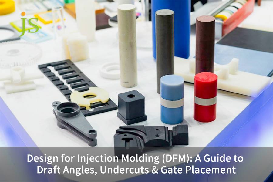

Design for injection molding (DFM) optimizes part geometry (e.g. Draft angles undercuts gate placement) so that tooling risk is minimized, defects are eliminated, and the unit cost is controlled.
By setting 1°-3° draft, eliminating multi-cavity sliders mechanisms, and accurately gate locating, tooling cost is reduced by 20%-35% and first-pass success rate becomes as high as >98%. Read on for JS Precision engineering team's summary of the rigorous DFM rules.
Design for Injection Molding (DFM) Critical Technical Parameters Matrix
|
DFM Dimension |
Standard Recommendation |
Defect Control Target |
Cost & Cycle Impact |
|---|---|---|---|
|
Draft Angle |
Plain surface: 0.5°–1.0°. SPI-B3 texture: 1.5°–2.0°, add 1° per 0.013mm etch depth |
Drag marks, ejection white, pull damage, ejection deformation |
15% fewer ejection mechanism failures & trial costs |
|
Undercut Design |
Bump-off strain < 5%, slider stroke 5–50mm, prioritize cross-over cores |
Cracking, flash, mechanism jamming |
Removing sliders saves $1,500–$4,500 tooling cost |
|
Gate Placement |
Gate thickness 50%–80% of nominal wall, locate at thickest wall, away from stress points |
Sink marks, weak weld lines, air traps, warpage |
20% shorter pack & cycle time |
Key Takeaways
- Draft Angle & Texture Matching: If SPI/MT surface texture is deep, draft angles have to be modified, deep-cavity structures should be provided with at least a 1° draft increment for every inch of depth.
- Prioritizing Pass-through Structures for Undercuts: To economize and prolong mold life, pass-through cores should be prioritely considered instead of mechanical slides.
- Gate-Driven Flow Balance: Gates should be placed in the thickest wall sections, so the melt runs from thick to thin, use Moldflow analysis to eliminate weld lines and shear stress.
- Early DFM Integration: Invoving the JS Precision team in DFM analysis before CAD designs are fully completed can get rid of more than 90% of estimated rework costs later on.
Why Trust JS Precision’s DFM Injection Molding Service To Optimize Part Design?
According to industry best practices, DFM's value extends beyond merely checking drawings. It is actually about getting the manufacturing risks cleared up before the steel cutting phase starts. Using the high-frequency pneumatic controller housing project as a reference, the original design incorporated four deep-lateral cavity undercuts and a main wall thickness of 4.2mm with extremely varying thickness. In such a situation, we would have been facing a mold cost 35% over the budget if we just followed the original design.
After the intensive DFM optimization (uniform reduction of the main wall thickness to 2.2mm, replacement of three hydraulic slides with pass-through cores, implementation of the dual-point submarine hot runner gate system), we succeeded both in cutting down the mold costs by 30% (saving $6.8 thousand), and in speeding up the molding cycle from 45 seconds to 32 seconds. Also, we passed the 1-million-cycle high-frequency vibration fatigue test with no problem.
The ISO 9001:2015 standard demands of the entities, not only to have and run a quality management system but at all times to develop and improve this system by establishing implementing maintaining, and continuously improving a quality management system.
In its DFM injection molding services, JS Precision strictly follows the mentioned standard by deploying a fully traceable, comprehensive closed-loop quality control system. The system also includes process capability verification with Cpk≥1.33.
Want to eliminate 90% of potential post-production rework costs before finalizing the CAD design? Download JS Precision’s DFM Checklist to access detailed verification criteria for draft angles, undercuts, and gate locations.
Why is Draft Angle Design Critical for Smooth Part Ejection in Injection Molding?
Draft angle design creates a slope along the mold-opening direction on the sidewalls, thereby eliminating vacuum suction and frictional resistance during the moment of ejection. Proper draft angle configuration prevents surface scuffing and reduces sidewall friction by over 80%, serving as the foundation for smooth, automated ejection.
The relationship between surface texture and draft angles
Understanding the physics of the draft angle design process means matching them to certain surface roughness grades. In design for injection molding review, SPI Standard Surface Texture has a hard draft requirement:
|
SPI Finish |
Surface Texture |
Roughness Ra (μm) |
Min. Draft Angle |
|---|---|---|---|
|
SPI A1 |
Diamond buff (high gloss) |
0.012–0.025 |
0.5° |
|
SPI A2 |
Diamond buff (semi-gloss) |
0.025–0.050 |
0.75° |
|
SPI B1 |
#600 grit paper |
0.05–0.10 |
1.0° |
|
SPI B2 |
#400 grit paper |
0.10–0.20 |
1.25° |
|
SPI C1 |
#600 stone |
1.0–2.0 |
1.5° |
|
SPI C2 |
#400 stone |
2.0–3.2 |
2.0° |
|
SPI D1 |
Dry blast glass bead |
3.2–5.0 |
2.5° |
|
SPI D3 |
Heavy dry blast |
6.3–12.5 |
3.0°+ |
Material Shrinkage and Draft Angle Calculation
- Crystalline materials (PA66, POM): These materials show a high shrinkage (1.5%-2.5%), it is wise to have a draft angle of 1.5°-2.0° so that after ejection, there is no scuffing, as an excessive gripping force was used.
- Amorphous rigidd materials (PC, ABS): These materials have low shrinkage rates (about 0.4%-0.7%) and the minimum draft angles are 1.0°-1.5°. But, polycarbonate (PC) will need 1.5 because it is stress-sensitive.
- How draft works with textures: The more the texture depth, the bigger the draft angle. For every 0.013 mm increase in texture depth, you can give an extra draft of 1°. Deep cavity structures should at least have a draft that increases by 1° per inch.
Failure Modes Due to Insufficient Draft
If the injection mold designer makes a draft angle too small on the blind holes and deep cavity ribs of the mold part it can cause vacuum induced whitening, scratching & dragging, or in the extreme case, halt of the production. Injection molding: Sidewall friction is exponentially related to draft angle:
F_friction ∝ μ × cos(α) × P_vertical
Where α is the draft angle, μ is the coefficient of friction, and P_vertical is the gripping force. Increasing α from 0.5° to 2.0° reduces friction by more than 80%.
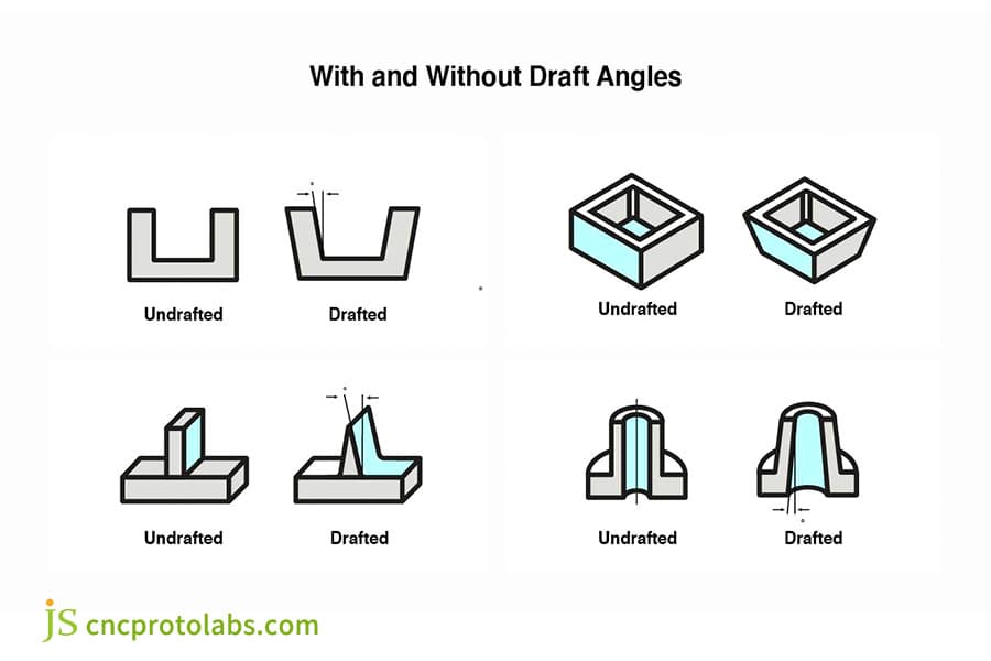
Figure 1: Diagram comparing undrafted and drafted plastic parts.
How Can Optimizing Undercut Molding Design Reduce Injection Mold Tooling Costs?
Optimizing undercut molding design can reduce or eliminate expensive side-action mechanisms (side cores) in the mold. By converting complex undercuts into features molded directly at the parting line, mold manufacturing costs can be reduced by 20%-40%, and molding efficiency significantly improved.
Comparison of Undercut Solutions
A systematic overview of geometric solutions for undercut molding design, the four common methods used in custom injection molding service are compared below:
|
Solution |
Tooling Cost |
Applicable Geometry |
Lifespan Limit |
Tolerance Range |
|---|---|---|---|---|
|
Slider |
Base + $1,800–$4,500 |
External undercuts, stroke 5–50mm |
500k+ shots |
±0.02mm |
|
Lifter |
Base + $1,200–$3,000 |
Internal undercuts, limited stroke |
300k shots |
±0.03mm |
|
Pass-through Core |
Base + $200–$600 |
Through-thickness features |
1M+ shots |
±0.05mm |
|
Bump-off |
Base only |
Flexible materials only |
200k shots |
±0.10mm |
Allowable Strain for Bump-off (Forced Ejection)
Suitability for forced ejection varies significantly by material:
- Flexible materials: PE and PP can tolerate up to 5% elastic deformation which qualifies them as bump-off design materials.
- Semi-rigid materials: ABS and PC can only deform elastically up to a very small extent below 1%, so their use in bump-off design is discouraged due to the high risk of breaking during ejection.
- Strengthened materials: PA66+30%GF and POM become highly brittle after the glass fiber reinforcement or the increased crystal content, so any forced ejection of the part is totally prohibited and only mechanical ejection is allowed.
Cost-reduction strategies
- External undercuts: Use snap-fits and shut-off cores instead of hydraulic slides.
- Internal undercuts: Transfer features to the parting line with overlapped recess-cutouts, use lifters instead of exterior hydraulic slides that are costly.
- Advantages in cost reduction: Removing one slide reduces mold tooling costs by 1,500-4,500 and increases service cycle.
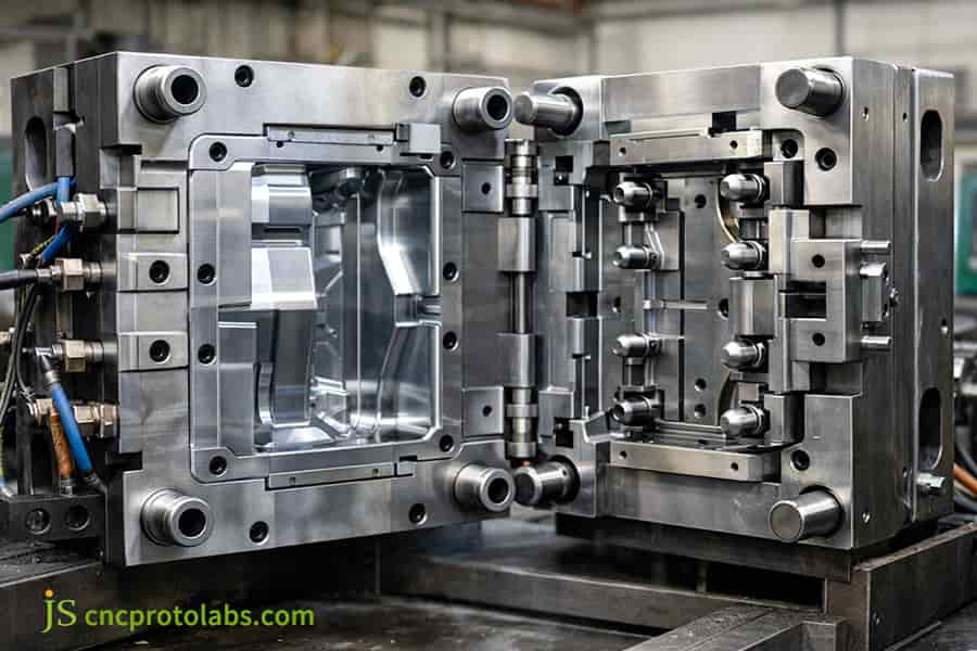
Figure 2: Precision mold with undercut features.
How Does Gate Placement Directly Impact Injection Molded Part Quality and Aesthetics?
Filling the cavity with a gate, a small opening, controls how molten plastic flows in, how pressure is transmitted and even controls cooling/crystallization. A correctly designed gate can make a part free of sink marks, decrease warping, and direct weld lines to such places that they neither support load nor show.
Type comparison between gates
For injection molding service, the gate types are decided based on part requirements:
- Edge Gate: In edge gates, thickness of the gate is typically 50-80% of the nominal wall thickness, although trimming costs are low, the cosmetic surface is marked.
- Submarine (Sub) Gate: The gate is situated in a non-aesthetic area where gate shearing is automated, it is recommended for glass-fiber-reinforced materials like PA66+30%GF.
- Hot Runner Valve Gate: It saves cold runner waste and gate marks, a great match for visually appealing parts, with a break-even point at 3-6 months.
Gate-driven flow balance
In DFM for injection molded parts, follow the packing principle of flow from thick walled to thin walled sections:
Shear Rate = (6 × Q) / (w × h²)
Where Q is the volumetric flow rate, w is the gate width, and h is the gate thickness. If h is too small and the shear rate exceeds 100,000 s⁻¹, jetting marks will occur.
Precision Control for High-End Cosmetic Parts
JS Precision takes the use of submarine hot gates for their premium injection molding service to the next level by not leaving any trace at all on the surface of the parts. Their high-strength parts, undergo Moldflow analysis not only to anticipate anisotropic molecular shrinkage but also to tackle the challenge of part warping resulting from that shrinkage.
Concerned about visible gate marks on your product's cosmetic surfaces? Upload your drawings, and JS Precision will tailor a concealed gating solution for you.
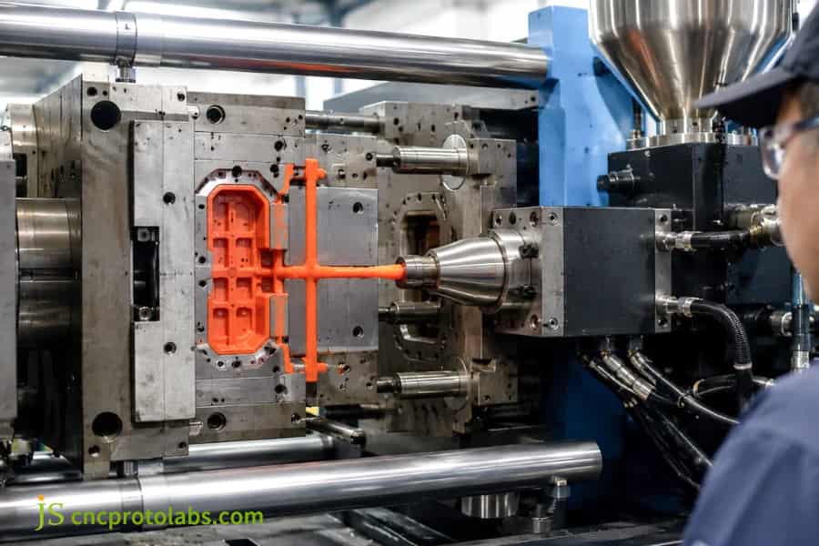
Figure 3: Gate location affects injection molded part aesthetics.
How to Balance Wall Thickness and Tolerances in an Injection Molding Design Guide?
The injection molding design guide stresses that keeping the wall thickness uniform is the main rule to avoid sink marks, internal voids, and severe warpage of plastic parts. Sticking to tolerances compatible with what manufacturing can realistically deliver helps reduce mold costs caused by adding unnecessary features.
Engineering Plastic Wall Thickness and Tolerance Capabilities
As a core supplement to a comprehensive injection molding design guide, the parameters for common engineering plastics are as follows:
|
Material |
Nominal Wall (mm) |
Rib Ratio |
Commercial Tol. (mm) |
Precision Tol. (mm) |
|---|---|---|---|---|
|
ABS |
1.5–3.5 |
50%–60% |
±0.10 |
±0.025 |
|
PC |
1.5–3.0 |
50%–55% |
±0.12 |
±0.030 |
|
PA66+30%GF |
1.2–3.0 |
40%–50% |
±0.15 |
±0.040 |
|
PEEK |
1.0–4.5 |
50%–60% |
±0.10 |
±0.025 |
Three Golden Rules for Wall Thickness Design
Adhere to the following principles in design for injection molding:
- Uniform wall thickness: The nominal wall thickness is around 1.5-4.5 mm, the thickness transition ratio should not exceed 3:1, for thickness changes, use gradual transitions.
- Ribs instead of thick walls: The base thickness of a rib should be 50%-60% of the thickness of a standard wall, the height shouldn't exceed 5 times the thickness, root radius (fillet) ≥0.5T.
- Rationalize tolerances: There is a great difference in the costs of mold-making between commercial-grade (±0.10 mm) and precision-grade tolerances (±0.025 mm), you should not put precision tolerances on all parts of the drawing if non-mating surfaces are considered.
Cost Impact
Uneven wall thickness can lead to sink marks, voids, and weld lines. Optimizing wall thickness distribution through DFM can reduce material consumption and cooling time by 20%-30%.

Figure 4: Automated production line with quality control.
How Does Moldflow Analysis Prevent Manufacturing Defects in DFM Injection Molding Service?
The DFM injection molding service uses Moldflow simulation to see melt flow, cooling, and stress distribution before mold steel machining begins. It identifies perfectly air pockets, trapped air, and weld lines enabling design changes to be made during the digital phase avoiding major financial burden.
Four Main Modules of Moldflow Analysis
The total DFM injection molding service is based on these simulations:
- Fill Analysis: Foreseen short shots, weld line locations, and melt front temperatures in a targeted fill time of 0.5-2.0 sec.
- Pack Analysis: Shrink sink and volumetric shrinkage are the main factors that the calculation takes.
- Cool Analysis: By optimizing the cooling channels, one can make the mold core surface temperature difference less than ±2℃ and reduce cooling time by 15%-25%.
- Warp Analysis: Warp deformation measurement as well as optimization of the gate placement by the limitation of deformation within ±0.1 mm.
Guiding Physical Manufacturing with Simulation Data
To prevent defects efficiently, the pressure drop data gained from Moldflow analysis needs to be converted into injection molding machine setting parameters.
As ISO 294-1:2017 regulation, the injection speed shall be set so that the mould fills in 0.5 to 2 seconds.
To comply strictly with this norm, JS Precision correlates Moldflow pressure drop information (e.g. End-of-fill pressure drop ≤15 MPa) with the machine's injection profile settings. This is to make sure that the fill time is within 0.5-2.0s range to avoid such defects as flash or incomplete filling.
Eliminate risks before mold cutting! Send your CAD drawings to JS Precision to receive a professional Moldflow analysis report.
How to Select the Right Plastic Resin and Surface Finish for Your Molded Parts?
In custom injection molding service, the compatibility between the resin material and the surface texture directly determines the plastic part's mechanical strength, temperature resistance, and ease of demolding. Scientific material selection and surface treatment specifications are key to enhancing the product's overall performance and aesthetic quality.
Material Properties and SPI Surface Finish Matrix
Material selection matrix for DFM (Design for Manufacturability) in custom injection molding service:
|
Material |
MFI (g/10min) |
Mold Shrinkage (%) |
Recommended SPI |
Min. Draft Angle |
|---|---|---|---|---|
|
ABS |
10–25 |
0.4–0.7 |
SPI A2–B2 |
1.0° |
|
PC |
5–15 |
0.5–0.7 |
SPI A1–A3 |
2.0° |
|
PA66+30%GF |
10–30 |
0.3–0.6 |
SPI B1–C2 |
2.5° |
|
PEEK |
5–20 |
1.0–1.5 |
SPI B1–C3 |
1.5° |
|
PMMA |
2–10 |
0.2–0.6 |
SPI A1 |
3.0° |
Impact of Surface Finish on Demolding
- Polished Mirrors (SPI A1-A3): Ra ≤0.025μm, although these achieve the lowest friction, materials like PC, for example, will require a release angle of ≥2 to prevent stress cracking.
- Semi-gloss (SPI B1-B3): Ra 0.05-0.50μm, can be used for exposed parts of structural elements.
- Matte and Sandblasted (SPI C1-D3): For every 0.013mm increase in texture depth, you need to add 1° to the release angle.
- Fiber-reinforced materials: The direction of the fiber will cause the material to shrink irregularly, this problem has to be anticipated and solved by Moldflow simulation.
Special Considerations
Custom injection molding service that work with UV-resistant and fiber-reinforced materials have certain DFM aspects that they need to consider: fiber-reinforced materials are not allowed to be squeezed out of the mold, and proper gate design is an important element that can help avoid jetting marks.
How Did JS Precision Resolve DFM Issues for an Industrial Pneumatic Controller Enclosure?
In a project, the original design had serious shrinkage marks and 4 deep cavity lateral anti-misoperation buckles, which caused the estimated quotation of the mould exceeded the standard and the fatigue resistance test failed to meet the standard. With the involvement of the JS Precision team, the processing challenge was successfully solved through deep optimization.
Challenges Faced by the Client
The pneumatic controller housing was a UL94-V0 flame-retardant PA66+30%GF (glass fiber reinforced nylon) for the explosion-proof factory automation environments. The original blueprint had wall thickness of 4.2mm with very big variation in wall thickness, which resulted in the major internal shrinkage cavities and 0.08mm of warpage.
On the top of that, the side wiring ports had four deep-cavity undercuts, so they required four completely different hydraulic side-action slides. So, it pushed the mold cost estimation over by 35% compared to the client's budget.
JS Precision’s Solution
- Wall Thickness Redesign and Coring:
The overall wall thickness was reduced to a uniform depth of 2.2mm. The wall had a internal intersecting 1.2mm honeycomb rib structure of 55% of wall thickness. This new structure decreased the weight while increasing the overall flexural modulus by 20% and at the same time getting rid of sink marks.
- Simplification Of Undercut:
Parting line design was intelligently changed to get rid of the four side (lateral) undercuts for the molding, by using staggered pass-through cores that would have required external hydraulic slides. Three sets of expensive external hydraulic slides could have been saved since lifters at angle were used during the ejection process.
- Gate and Runner Optimization:
Gate sub-gate (submarine) system (two-point gate), was implemented that had gates placed along the internal base, away from the visual surfaces. That means, it prevented shrink age due to fiber orientation that was causing glass fiber imbalance during filling.
Lessons Learned
In the first Moldflow test, poor airflow at the fill end caused the flame retardant to be released under high pressure which resulted in localized burning (air traps). Following this, the engineering team added high-precision vents (with 0.025 mm depth) at the cavity face of the mold, thereby removing the air entrapment and burning problems completely.
Final Results
|
Parameter |
Before JS Precision |
After JS Precision |
|---|---|---|
|
Tooling cost |
Baseline ($22,800) |
-30% ($6,800 saved) |
|
Pack & cycle time |
45 s |
32 s (-29%) |
|
Critical hole pitch tolerance |
Out of spec |
±0.015 mm |
|
Fatigue test |
Failed |
Passed 1,000,000 cycles |
Facing similar complex DFM challenges? Contact JS Precision for a DFM assessment and a complimentary, customized cost-reduction plan.
Why Choose JS Precision as Your Precision Injection Molding Service Partner?
With over 15 years of experience in precision mold making and injection molding production, JS Precision is dedicated to providing global clients with one-stop services-from free assessments to mass production delivery. We ensure the successful commercialization of every project through rigorous ISO quality systems and exceptional technical responsiveness.
Four Core Competitive Advantages
As your injection molding partner, JS Precision offers:
- Free DFM & Mold Flow Analysis: Technical analysis & optimization suggestions are offered after 24 hours from receiving the inquiry.
- Advanced Machining & Precision Tolerance Control: We have an imported high-efficiency CNC machine, mirror-finish EDM, CMM inspection system, mold machining accuracy ±0.005mm.
- Flexible Production & Manufacturing Capabilities: Support for a diverse range of services including rapid manufacturing and mold trials (T1 samples are available in 10 days) up to high-volume manufacturing runs of 100,000 units.
- Totally Transparent Process: The provision of material quality reports and 3D dimensional inspection data ensures full traceability of quality.
Customer Value Proposition
Choosing JS Precision means that your project achieves: 99.2% on-time delivery rate, 99.8% finished product qualification rate, and a process capability guarantee of Cpk ≥ 1.33. Each shipped product comes with a complete size traceability chain.
FAQs
Q1: What is the standard draft angle for injection molded plastic parts?
The conventional draft angle typically ranges between 1°-2°. A minimum of 0.5°-1° is needed for a smooth finish, whereas textured surfaces need an added 1° for every 0.013mm of texture depth to prevent the surface from scratching or appearing stressed during removal.
Q2: How can I remove undercuts from my plastic part design to lower tooling costs?
Dry holes and moving undercuts to the parting line can be methods to get rid of hydraulic sliders which in turn can reduce mold costs by a third of the time and also increase mold life.
Q3: Why is gate placement crucial for cosmetic and structural part quality?
The location of gates has a major impact on flow paths and how well-packed the material is. If the gate is placed at the part with the thickest wall, this not only helps in avoiding sink marks but also keeps weld lines out of the areas that will be visible to the customer or carry the weight of the piece.
Q4: How much does a custom injection molding service cost at JS Precision?
The cost of aluminum prototype molds begins at $1,500 whereas precision steel molds can be obtained at a cost between $3,000 and over $15,000. Also, JS Precision offers free DFM analysis to make your design as efficient and less expensive as possible right before the tooling process begins.
Q5: What plastic materials require the largest draft angles in DFM?
Largely because of their high hardness and high melting temperature, materials such as PC, PMMA, and glass-fiber reinforced plastics tend to need larger draft angles. As a general rule, JS Precision says that you should have a minimum of 2°-3° draft on vertical surfaces to limit mold damage through friction on ejection.
Q6: How does DFM optimization help avoid sink marks in thick sections?
By lowering wall thicknesses and using ribs as reinforcement sinks are minimized through DFM. Normally, the rib base thickness should be about 50%-60% of the main wall to be able to prevent surface defects from being produced by temperature differences and shrinkage.
Q7: How long does it take to receive a detailed DFM report from JS Precision?
JS Precision issues a complete DFM report 24 hours after we receive your 3D CAD files. The report discusses draft angles, wall thickness, undercuts, and gate placement, along the way including a competitive quote.
Q8: Can I manufacture complex plastic parts with undercuts without using expensive sliders?
Absolutely! Expensive slides can be substituted with lifters, collapsible cores, or segmented inserts. During the DFM design stage, the engineering department at JS Precision will identify the most economical structural solutions for you.
Summary
Designing injection-molded parts requires balancing functionality, aesthetics, and manufacturability. Implementing DFM principles early on-such as properly allocating draft angles, avoiding costly undercuts, and precisely positioning gates-can eliminate over 90% of defects at the source, significantly reducing mold lead times and costs. Mastering these principles is key to ensuring the smooth mass production of plastic parts.
Want to ensure your next injection molding project launches successfully? Send us your 3D CAD drawings today to receive a free 24-hour DFM assessment report-covering draft angle checks, undercut optimization, and mold flow analysis-along with a competitive quote, and start your high-precision manufacturing journey with JS Precision!

Disclaimer
The contents of this page are for informational purposes only. For JS Precision Services, there are no representations or warranties, express or implied, as to the accuracy, completeness, or validity of the information. It is the buyer's responsibility to identify specific technical requirements and request a formal parts quotation. Please contact us for more information.
JS Precision Team
Custom manufacturing solutions. With over 15 years of experience serving more than 1,000 customers, we specialize in high-precision CNC machining, sheet metal fabrication, 3D printing, injection molding, and metal stamping. Having successfully delivered over 300,000 precision parts, we maintain a 99.2% on-time delivery rate across all custom projects.
Our facility is equipped with over 100 state-of-the-art 5-axis machining centers and is ISO 9001:2015 certified. We deliver fast, efficient, and high-quality manufacturing solutions to B2B clients across 150 countries. Whether you require low-volume prototyping or large-scale customization, we support your project with lead times as short as 24 hours. Choose JS Precision for unparalleled efficiency, quality, and professionalism.
To learn more or submit your RFQ, visit our website: www.cncprotolabs.com
Resource

