 English




PC injection molding is hindered mainly by three problems: high moisture absorption, high melt viscosity and narrow process windows. Even a tiny ±5℃ drying deviation or moisture level in excess of 0.02% can result in non-reparable defects such as silver streaks, bubbles or stress cracks.
Derived from JS Precision's practical engineering knowledge, this handbook outlines step by step, the underlying causes and corrective measures of silver streaks, weld lines, internal stress, and mold surface defects, providing assistance for technicians and purchasing staff in identifying and minimizing quality risks when a custom clear part molding service is required.
A Quick Overview Of The Core Information Of Transparent PC Injection Molding Parts
|
Challenge Type |
Core Root Cause |
Key Control Standard |
Typical Consequence |
|---|---|---|---|
|
Silver Streaks / Bubbles |
Moisture > 0.02% |
Dew point -40°C dryer, 120-130°C × 4-6h |
Surface streaks, internal voids, scrap |
|
Short Shots / Weld Lines |
High melt viscosity, insufficient fill |
Mold temp 80-120°C, injection pressure 130-180MPa |
Incomplete fill, strength drop at weld line |
|
Warpage / Stress Cracking |
Uneven cooling, frozen residual stress |
Wall thickness 1.5-3.5mm, annealing at 120°C |
Dimensional deviation, post-assembly cracking |
|
Haze / Flow Marks |
Insufficient mold polish, poor venting |
SPI A-1/A-2 mirror finish (Ra ≤ 0.02μm) |
Optical transparency failure |
Key Conclusions
- Moisture level in the PC resin at injection should not exceed 0.02%. Overhydration results in 60% of PC molding issues and is the most common reason for defects in the molded parts.
- The cavity of the mold for transparent plastic PC parts must show a mirror finish up to SPI A-1 or A-2 grade.
- The mold temperature must be kept between 80 and 120 degrees Celsius. It should be considered that every 10 degrees increase from the recommended range will result in significant stress changes in product geometry.
- The minimum and maximum suggested wall thicknesses are 1.5-3.5mm, and transition fillets are required at those points where the material change is abrupt.
Why Trust JS Precision's Custom PC Injection Molding Service?
Leveraging over 15 years of precise PC plastic injection expertise within the automotive and medical supply chains, your custom clear projects can bypass common thermal defects from day one that to get a really good solution of PC injection molding problems, a custom clear part molding service, the capability of the machine must include moisture content control throughout the process, the ability to produce optical-grade molds, and process parameters optimization.
Based on 3 months of processing test data, we have seen that over 60% of all PC molding defects are due to improper drying. In fact, we have noticed that many suppliers only control drying time but pay no attention to the dew point.
Plastics, Injection molding specimens (ISO 20753:2023) explicitly states that the preparation of injection molded specimens shall be carried out under controlled conditions, and the moisture content of the material shall be determined and recorded before injection molding.
So the PC projects will be accompanied by dehumidifying dryers with a dew point ≤-40℃, and we have decided that the moisture content of the material will be tested by a moisture analyzer before the materials get into the dryer.
For a medical device with a PC transparent viewing window, the customer's previous supplier had a scrap rate of more than 70%. By redesigning through DFM, we switched to a fan gate instead of a single-point side gate, raised the mold temperature from 75℃ to 105℃, and also included 2h of heat-treatment at 120℃. We managed to bring the rejection rate down to below 4%.
Want to assess whether your PC injection molding project has defect risks? Contact our engineers to obtain the PC Injection Molding Defect Prevention Self-Checklist, covering drying parameters, mold temperature, and gate design.
What Are The Root Causes Of Silver Streaks And Bubbles In PC Injection Molding?
A main reason for silver streaks and bubbles in PC molding is the hydrolysis reaction triggered by moisture content beyond 0.02%. The hydrolysis reaction degrades the polymer chains, produces CO₂, and leaves imperfections visible on the transparent parts' surface.
Mechanisms Of Silver Streaks & Bubbles:
- Hydrolysis Reaction: The ester bonds in PC molecule chains are very water-sensitive. At a temperature around 280-310℃, PC reacts with moisture, the molecular weight falls followed by the release of a gaseous component. The root cause of polycarbonate molding challenges often begins with drying.
- Gas Sources: Water vapor, entrained air, thermal decomposition gases, and solvent gases are the gas sources. These four are the main gas types.
- Morphological Character: The silver streaks on plastic parts may usually be of a U-shape colorless streaks that are radiated outward by the parting line, vacuum bubbles are located on the thick-walled region, which is due to the lack of sufficient holding pressure that causes shrinkage in volume.
Solutions Summary
- Drying Standard: Drying at a temperature of 120-130℃ in a dehumidifier with a dew point of -40℃ for 4-6 hours.
- Moisture Content Checking: The material should have a moisture content < 0.02%. The first step in PC molding defects troubleshooting is always to measure the moisture content.
- Machine and Process Check: Test if the screw closes tightly, and check by cleaning the screw and barrel and avoid having degradation products.
- Process Modification: If the reason of the silver streaks is shear-induced overheating, decrease the screw speed (e.g. 50 to 100 rpm).
So the bottom line is, over 90% of the silver streaks on PC are due to high moisture content of the raw material, the measurement of moisture content is more powerful than other methods like changing production parameters.
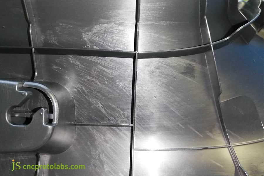
Figure 1: Silver streaks and bubbles on PC injection-molded part surface.
How To Resolve Short Shots And Weld Lines In Clear Polycarbonate Molding?
Clear polycarbonate molding with PC materials have high melt viscosity, resulting in difficult thin-walled filling (Mainly with wall thicknesses <1mm). Also, welded line strength can be about 14% weaker than the body. The fix is to go through optimization of gate design, mold temperature, and injection speed in an orderly manner.
PC Melt Behavior Characteristics
- Amorphousness: PC material is an amorphous thermoplastic which has no clearly defined melting temperature point since it softens slowly within the 230-320℃ range. Knowing its rheological properties is vital to solve common polycarbonate molding challenges.
- Viscosity Dependency: Melt characteristic similarity to Newtonian fluid means viscosity is mostly changed by temperature rather than by shear rate. This means that the effect of improving flow solely by increasing injection pressure is limited, and temperature control is the key.
- Thin-walled Parts: For wall thicknesses under 2mm it is suggested to use a melt temperature around 285-305℃.
Gating Methods and Processing Conditions
- Gating Type: Pin gates are a good choice for high-viscosity PC material since these can generate shear heat and reducing melt viscosity, film gates spread along the edge part and are fit for ultra-thin flat parts to achieve synchronized filling. The custom clear part molding service must be gating for part geometries.
- Mold temperture: 80-120℃, upper bound for thin-walled parts.
- Injection pressure: 130-180MPa (1300-1800bar).
- Segmentation: Segmented injection was applied where short speed increase was possible in the weld line zone.
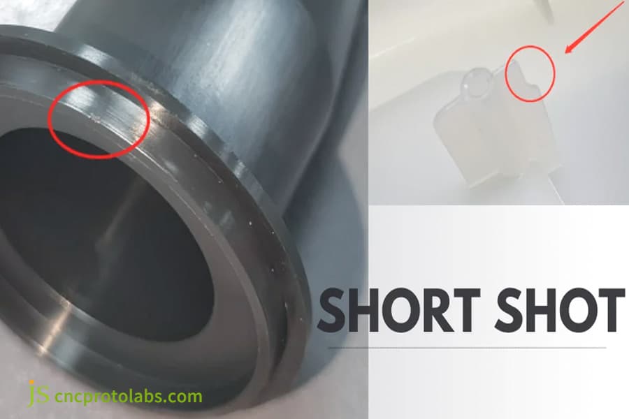
Figure 2: Short shot defect in clear polycarbonate molded part.
What Is The Mechanism Of Warpage And Stress Cracking Caused By Internal Stress In Clear PC Parts?
Polycarbonate has very poor thermal conductivity - only 0.19-0.22 W/(mK). As a result, even when the part surface is quite hot in some areas, there are still cold areas, so cooling is actually very uneven. During the mold filling stage, the polymer molecules get stretched, and before they get a chance to relax and return to their original configuration, the chain is frozen. This unrelaxed molecular orientation creates severe residual stress, which functions as the primary root cause for parts warpage and delayed cracking of PC injection molded parts.
The Hidden Nature and Detection of Internal Stress
- Delayed Cracking: The part looks very good when demolded but stress cracking is discovered days or weeks later after handling contact with chemicals (e.g. cleaners lubricants, threadlockers) or after assembling. The thing ESC is the most harmful of the major polycarbonate molding challenges.
- Source of stress: Excessive holding pressure leads to the freezing of the molecules orientation, excessively low mold temperature causes very quick cooling. Sudden differences in wall thickness cause difference in cooling rates.
- Detection Methods: Solvent immersion method (glacial acetic acid/ethyl acetate) and polarized stress meter detection.
Solution Key Points:
- Wall thickness Design: Aim for a consistent wall thickness of around 1.5-3.5mm - do not design a sudden change.
- Annealing Operation: The optimal time to perform annealing is 120℃ and the holding time is decided based on wall thickness. Annealing treatment can bring the tensile yield strength up by about 20 percent.
- Holding pressure Control: Switch holding pressure when the cavity is at 80-85% filling stage to reduce residual stress.
- Mold temperature Control: Do not make a temperature lower than 80℃.
What Are The Specific Requirements For Mold Surface Finish In Optical Clarity Injection Service?
With the optical clarity injection service, transparent PC parts are actually optical lenses. Each micrometer of roughness of the mold surface will cause either cloudiness or flow marks on the part surface. SPI A-1 mirror finish (Ra≤0.02μm) is the minimum requirement for transparent PC of optical-grade modeling.
Mold Surface Finish Standards
- SPI Grade: SPI grades the mold surface finish from grade 1 to 12. In transparent PC parts, cavities and cores should achieve SPI A-1 or A-2 standards at least. This requirement must be clearly stated in the mold specifications of clear plastic injection molding service.
- Polishing Process: A-1 mirror finish is achieved through diamond paste polishing resulting in a surface roughness of Ra≤0.02μm.
ISO 10137:2007 specifies that the surface roughness Ra of the mold cavity of optical injection molded components should be ≤ 0.02μm, and re polishing verification should be carried out every 50,000 molds.
To align with this standard, we have mandated the inclusion of SPI A-1 (Ra ≤ 0.02 μm) and S136H steel in the mold specifications for the transparent PC project, and have agreed to re cast every 50,000 molds.
- Mold Steel: Mold steels S136H and NAK80 are commonly selected because of their resistance to corrosion and ability to keep a high polished surface.
Ventilation System Design
- Vent Groove Depth: The vents are generally 0.02-0.03mm and placed at the melt flow end and parting line.
- Maintenance Cycle: Optical-grade molds should be inspected and polished after every 50,000 cycle runs as the polished surface deteriorates over time.
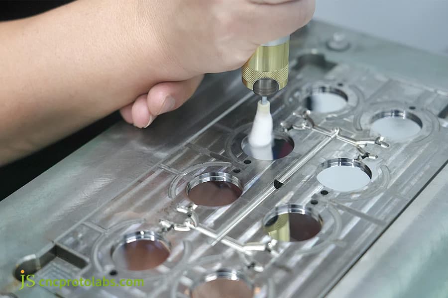
Figure 3: Polishing mold surface for optical clarity injection.
How Should Barrel Temperature And Injection Pressure Be Set In PC injection molding?
In order to maintain the right temperature settings for PC injection molding, it has to be controlled at several levels. The temperature must be dropped gradually from the nozzle towards the back of the barrel, with an upper limit of 285-305℃ for thin-walled parts, injection pressure should be set to 130-180 MPa. A temperature difference of ±10℃ might cause damage to the material or result in an incomplete mold filling.
Barrel Temperature Zones
- Rear Section: 260-280℃
- Middle Section: 270-290℃
- Front Section: 280-300℃
- Nozzle: 270-300℃ (it needs to be 5-10℃ cooler than the front section to keep drooling under control)
Process Parameters Per Part Thickness
|
Part Type |
Melt Temperature |
Mold Temperature |
Injection Pressure |
Key Consideration |
|---|---|---|---|---|
|
Thin-wall (<2mm) |
285-305°C |
80-100°C |
130-180MPa |
High melt temp ensures fill |
|
Medium-wall (2-5mm) |
270-290°C |
80-100°C |
110-150MPa |
Balance flow and stress |
|
Thick-wall (>10mm) |
250-280°C |
100-120°C |
98-130MPa |
Lower temp avoids degradation |
Because of very tight tolerance, PC injection molded parts require precise temperature settings, to ±5℃.
Download the PC Injection Molding Process Parameter Setting Table, input the wall thickness and flow length ratio, and the system will automatically recommend melt temperature, mold temperature, and pressure.
How To Select Between PC And PMMA In Clear Plastic Injection Molding Service?
Cases may appear where clear plastic injection molding service is needed for optical clarity instead of being the focus on impact strength. In these circumstances, PMMA is a likely candidate to use rather than PC. For one thing, its light transmittance level reaches 91-93% as against 88-90% from PC and, at the same time, it offers more excellent molding flow properties.
Key Selection Criteria:
- Optical performance: PMMA has a much higher transmittance compared to PCs - 91-93% versus 88%. If optical quality is a unique requirement then PMMA is going to be the material of choice.
- Mechanical strength: Impact strength of PC is 250 times better than glass. Whereas the counterpart for PMMA is only 10 times. In situations involving stresses like vibrations, shocks, or drops during assembly PC seems to be a better material alternative.
- Heat resistance: PC can maintain its shape under heat distortion at 130-140℃ whereas PMMA is unable to do so at 85-105℃. So PC should be chosen when a high-temperature environment is involved.
PC vs PMMA Selection Comparison Table
|
Comparison Dimension |
PC |
PMMA |
|---|---|---|
|
Light Transmittance |
88-90% |
91-93% |
|
Impact Strength |
250× glass |
10× glass |
|
Heat Deflection Temp |
130-140°C |
85-105°C |
|
Mold Shrinkage |
0.5-0.7% |
0.2-0.6% |
|
Mold Temperature Range |
80-120°C |
50-80°C |
|
Melt Temperature Range |
260-310°C |
210-250°C |
|
UV Stability |
Sensitive (yellowing without stabilizer) |
Good |
|
Relative Cost |
Baseline |
Similar material cost, lower processing cost |
- If your project mainly emphasizes optical transparency and surface hardness and doesn't have high impact requirements, then PMMA is the best fit.
- If there are assembly stresses or high-temperature environments, PC would be an acceptable choice.
Choosing the right optical clarity injection service depends on evaluating both performance and cost aspects thoroughly.
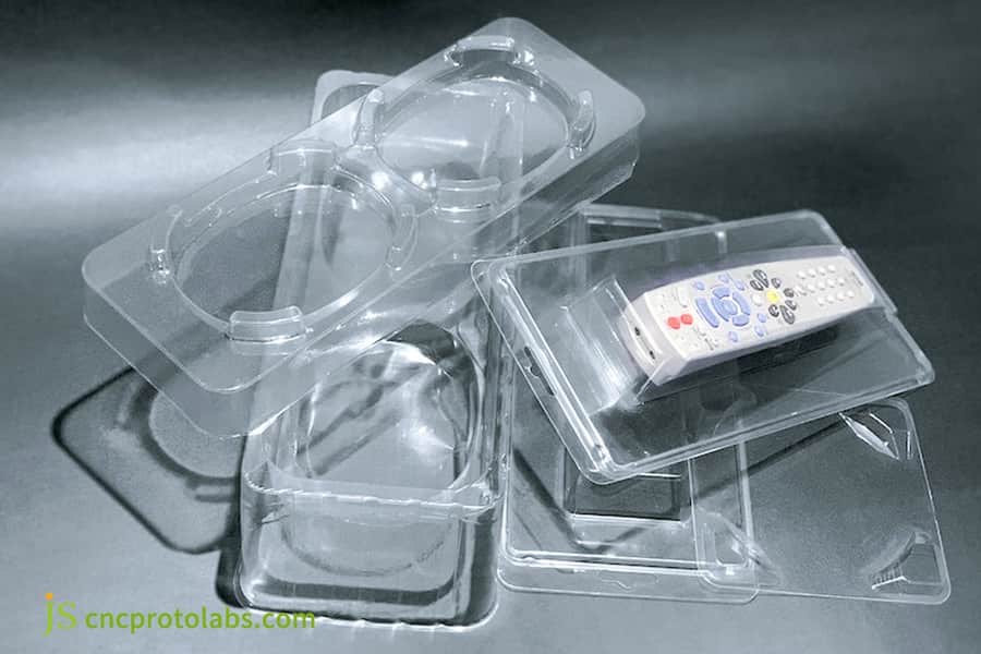
Figure 4: Clear PC and PMMA plastic parts comparison.
How Does JS Precision Solve Molding Challenges Of Clear PC Parts Through a Real Manufacturing Case?
In the custom clear part molding service project executed by JS Precision for a medical equipment customer, a transparent PC observation window with a wall thickness of 4mm underwent three rounds of trial molding, from the first round being 100% scrapped to the final optical inspection passing in one go. The key turning point lies in the fundamental adjustment of gate design and annealing process.
Customer Challenges
Medical device manufacturer from North America wants to personalize transparent PC viewing windows (120x80x4mm). Requirements are that light transmission of the part to the device shall be 88%, no defects visible with naked eye, and no stress cracking upon contact with medical disinfectant (isopropyl alcohol) after assembly. When the customer turned to their former supplier, rejection rate was above 70% at trial molding stage and main defects were still vacuum bubbles in the thick-walled area and random cracking after assembly.
JS Precision Solution
- Defect Diagnosis and Root Cause Analysis:
The vacuum bubbles were mainly found at the center of the thick-walled part at the center (4mm), the defect was mainly from volume shrinkage due to insufficient holding pressure. To confirm if it was cracking by residual stress, solvent immersion (glacial acetic acid) was used. The cracking was confirmed to be from residual stress.
- Gate redesign:
Initially, a single-point side gate (3mm), by the time the melt flow front got to the middle of the wall with the thick wall, the temperature had lowered already. A fan gate was introduced with the width enlarged 12, so that the melt front would enter the cavity accompanied by a more even temperature and pressure distribution.
- Changing the process parameters systematically:
Mold was brought up to 105℃ from 75℃, injection pressure was adjusted to 145MPa from 120MPa, the holding pressure switching point was shifted from 95% cavity filling to 85%, holding pressure was boosted from 30% to 50% of the injected pressure.
Lessons Learned from the Failure
The first trial molding focused only on a fan gate without addressing mold venting, which caused scorching as the air in the cavity could not be discharged properly. The second trial molding solved this by adding venting grooves (0.025mm depth).
Final Results
The third trial molding produced 50 parts which met all the quality standards, i.e. transmittance 89.2-89.7%, dimensional inspection within tolerance range (±0.05mm), and stress cracking free (no cracks even after being immerged in IPA for 72 hours). Yield stability during mass production is above 96%.
Rewarding PC injection molding is not so much about finding a remedy to a particular problem but developing a systematic approach and engineering method that can be easily replicated.
Your transparent PC project may also have similar room for optimization. Upload 3D drawings (STEP/IGS) and receive a free DFM assessment report within 48 hours, including defect risk prediction and process recommendations.
How To Systematically Troubleshoot And Resolve Common Defects In Clear PC Injection Molded Parts?
The first step in PC molding defects troubleshooting is systematically identifying the defect morphology. Each defect like silver streaks bubbles flow marks, black spots and stress cracks is characterized by specific morphology and has distinctive root cause. Getting the correct diagnosis can speed up the resolution by about 70 percent.
Defect Diagnosis Matrix
|
Defect Morphology |
Priority Check |
Verification Method |
Solution Path |
|---|---|---|---|
|
Silver streaks (radial from gate) |
Moisture → Shear heat → Degradation |
Measure moisture, check screw RPM |
Dry to <0.02%, reduce screw RPM |
|
Internal voids (thick area) |
Insufficient hold pressure |
Turn off hold pressure, observe void disappearance |
Increase hold pressure/time, advance switchover |
|
Surface haze/cloudiness |
Low mold temp, improper injection speed |
Measure mold temp, adjust speed profile |
Raise mold temp above 80°C |
|
Black specks/discoloration |
Barrel residue degradation |
Inspect screw, purge barrel |
Clean barrel, lower melt temperature |
|
Post-ejection cracking |
High residual stress |
Solvent immersion test |
Anneal at 120°C, reduce hold pressure |
Key Principles
- Drying takes the lead: Proper drying can eliminate about 60 percent of PC defects. First moisture level checking, then other parameters.
- A higher temperature results in a more effective flow and that better with the same pressure.
- Mold temperature is the biggest reason of internal stress for polycarbonate products. As for example, a ten degree Celsius raise in mold temperature decreases approximately fifteen to twenty percent of the residual stresses.
Why Choose JS Precision As Your Partner For Clear PC Custom Injection Molded Parts?
When selecting a reliable partner for custom clear part molding, apart from the price, it's important to take into consideration their experience in mold design, mold processing capability and technical support, etc. JS Precision has set up the service standards in all three areas through quantitative analysis and monitoring.
Core Competencies
- Process Database:
This refers to the company's ability to provide the best molding process for the different PC types such as flame retardant PC, medical grade PC, and UV-stabilized PC. In JS Precision, a moldflow analysis is done on every clear PC component before the first trial molding, and only two trial molding sessions are allowed. The technical background of JS Precision's transparent plastic mold injection depends on the data that was collected.
- Mold Capabilities:
JS Precision has its own mold shop fully equipped with high-speed CNC and mirror EDM machines and can finish mirror polishing at the SPI A-1 level (Ra≤0.02μm). S136H is the mold steel chosen. The producibility report will be delivered to the customer 48 hours after the DFM stage.
- Quality Inspection:
In the trial production stage, they will supply you with CPK report and optical testing report.In mass production, they will submit a traceability sheet of raw materials, daily logs of process parameters and periodic inspection reports for each batch. All transparent pc parts are produced per medical ISO 13485 or automotive IATF 16949 standards. Optical inspection mainly uses spectrophotometer and haze meter, and dimensional inspection refers to Zeiss coordinate measuring machines.
The standard production PC injection molding is a rate of trial molding success that is over a single run of 90% and a mass production yield over 96%.
Take Action Now: Send your 3D drawings to JS Precision to receive a free DFM evaluation report and a customized clear part molding service quote. Put your next transparent PC project on the track to success from the design stage.
FAQs
Q1: How precise can tolerance levels be for transparent PC injection molded products?
Tolerances of PC injection molded parts can reach ISO 2768-m standard, or even stricter tolerances like ±0.05mm, based on the complexity of the part, the way wall thickness is distributed, and the gate arrangement. Related to clear parts, as appearance is paramount, one should discuss how critical dimensions' tolerances can be handled with the mold maker right from the start.
Q2: How many custom transparent PC parts do you require per order?
The MOQ relies on the part size, number of mold cavities, and the material grade. Usually, with single-cavity tools MOQ is 500-1000 pieces, whereas with multi-cavity tools MOQ can be as low as 200-500 pieces.JS Precision also gives prototypes with mass production as per your request.
Q3: Why are transparent plastic parts free of defects immediately after injection but cracks a few days later?
This usually happens when the internal stress is too high and has remained in the parts. The stress from molecular alignment that was locked in at the time of manufacturing has now been released by the exposure to a foreign substance. Possible measures to prevent this are raising the mold temperature to around 100℃, incorporating a post-process heat treatment at 120℃, and lowering the holding pressure.
Q4: How do you measure/optical transparency of injected transparent parts?
The optical clarity is measured via three basic parameters: transmittance, haze and clarity. For the PC, light transmittance is around 88-90% on the average side.Testing is conducted utilizing spectrophotometer and haze meter, following ASTM D1003 standards.
Q5: What is the difference in cost of PC injection molding and PMMA injection molding?
PC price is nearly the same as the PMMA price, but since PC molding is harder, mold drying time is longer (from 4-6 hours for PC vs. PMMA's from 2-3 hours), higher mold temperatures (around 80-120℃ vs PMMA of 50-80℃), higher injection pressure all of these add to higher unit tooling cost making PC's mold cost 20-40% higher than PMMA on average.
Q6: What makes(JS) JS Precision stand out in transparent pc plastic (polycarbonate) injection molding?
JS Precision was transparent pc injection molding since 2015 and have mastered SPI A-1 polishing level mold fabrication. And, we maintain a PC-specific process reference library with our own developed molding techniques for optical materials. We support customers from DF analysis to pilot runs through full scale production, making your transparent pc plastic optics and dimensions as you desire the first time round.
Q7: What is the usual mold life for molding transparent PC parts?
It is standard for the mold life of PC parts (non-reinforced) to be 500,000-1,000,000 cycles assuming that corrosion-resistant materials like S136H are used for mold construction and that the polished surface is kept clean up regularly. Repolishing of the optical-grade molds to prevent deterioration is recommended every 50,000 cycles.
Q8: What is the right method to request a quote for custom transparent PC injection molded parts?
Please send your 3D files (STEP or IGS format), production requirement per year, clarity requirement, and dimensions tolerance to JS Precision. Our engineering team will carry out the Design for Manufacturing (DFM) review and furnish you with the quote details within 48 hours covering, mold cost, quantity cost and expected delivery time. You can directly upload the drawings to obtain a quotation, and JS Precision will respond quickly.
Summary
To injection mold transparent PC technically it is very challenging compared to other plastics. The moisture content in PC at less than 0.02% will be the red line to exceed. The melt temperature window is only around ±10℃, and SPI A-1 mold polish is the requirement, a failure at any stage will lead to irreversible defects of transparent PC parts. Besides, systematic process control is what ensures a good success rate, that means precise numerical values are to be applied at material drying, process parameters, mold design, and post-treatment annealing stages. With transparent PC parts it is no long of the question Is it possible? that it will become Is it reproducible?
Send us your 3D drawings and we'll generate a free DFM report for you and a quote for our custom clear plastics part molding service. PC molding of our experts help technical risk reduction and first pass success optical clear parts manufacturing for you with our support.

Disclaimer
The contents of this page are for informational purposes only. For JS Precision Services, there are no representations or warranties, express or implied, as to the accuracy, completeness, or validity of the information. It is the buyer's responsibility to identify specific technical requirements and request a formal parts quotation. Please contact us for more information.
JS Precision Team
Custom manufacturing solutions. With over 15 years of experience serving more than 1,000 customers, we specialize in high-precision CNC machining, sheet metal fabrication, 3D printing, injection molding, and metal stamping. Having successfully delivered over 300,000 precision parts, we maintain a 99.2% on-time delivery rate across all custom projects.
Our facility is equipped with over 100 state-of-the-art 5-axis machining centers and is ISO 9001:2015 certified. We deliver fast, efficient, and high-quality manufacturing solutions to B2B clients across 150 countries. Whether you require low-volume prototyping or large-scale customization, we support your project with lead times as short as 24 hours. Choose JS Precision for unparalleled efficiency, quality, and professionalism.
To learn more or submit your RFQ, visit our website: www.cncprotolabs.com
Resource

