 English




The K-factor in sheet metal bending is a mathematical ratio(K=t/ T) that defines the inward shift of the neutral axis relative to the total material thickness during plastic deformation. Because outer sheet fibers expand in tension while inner fibers compress, the neutral axis(the zero-stress plane inside the sheet where fibres neither stretch nor compress, so the material length stays unchanged) represents the zero-stress plane where material length remains unchanged. Accurate K-factor calculation prevents flat pattern dimensional errors before press brake tooling setup.
Summary Table of Core Answers
The K-factor governs sheet metal flat blank calculations, ranging from 0.30 to 0.50 based on localized strain and tooling mechanics.
|
Parameter |
Engineering Value |
Process Significance |
|---|---|---|
|
Definition |
K=t/T (neutral axis depth ratio) |
Locates the zero-strain interface during plastic bending. |
|
Range |
0.30 to 0.50 (air bending default: 0.44) |
Sharp bends drop below 0.33; coining exceeds 0.45. |
|
CAD Formula |
BA=(π/180) x A x (R+K x T) |
Converts 3D flange geometry into flat cut lengths. |
|
Variables |
Yield ratio, die width, grain direction |
Controls neutral axis displacement and springback. |
According to ISO 6892-1:2019, tensile testing of metallic materials establishes yield-strength baselines for K-factor calibration.
What Mechanical Principle Drives Neutral Axis Shift in Sheet Metal Bending?
In sheet metal bending, the neutral axis shift is the inward migration of the zero-strain plane caused by asymmetric plastic deformation. Outer fibers stretch in tension while inner fibers compress, which moves the neutral axis toward the inside bend radius. Fabricators calculate this behavior via the formula K=t/T, where standard mild steel typically yields a K-factor between 0.30 and 0.50 under air bending.
Mechanical Mechanism and Calculation of Neutral Layer Migration
- Perfectly elastic bending: the neutral layer lies exactly at the middle of the sheet thickness, K=0.50.
- Realistic air bending: The inner side gets a higher compressive strain than the outer side allows in tension, so that the neutral axis gets shifted towards the inner surface and the K value is between 0.30-0.50.
- Calibration Procedure:
Reverse-calculate K from a measured coupon: K = (BA / (90 × (π/180)) − R) / T then write the result into the CNC bending control. Across T = 1.0–6.0 mm SPCC coupons, JS Precision's 2025 test-bend records show 5–12% cross-section thinning in the bend zone, and this procedure held cumulative bend tolerance inside ±0.15 mm.
Simply put: K = t/T tells you where the neutral axis sits, and getting that right is what keeps a precision part on tolerance. To calculate the K-factor, measure the bend allowance on a test coupon first, then solve the bend allowance formula in reverse: K = (BA / ((π/180) × A) − R) / T.
For the full calculation workflow, see Bend Allowance Formula: K-Factor & Springback Guide.
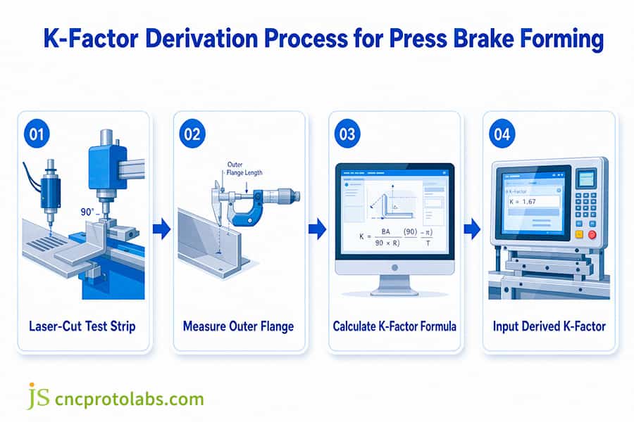
Figure 1: Flow chart for writing the actual K value calculated from the actual measurement of the test sample into the CNC bending control system.
What Is the Difference Between K-Factor and Bend Allowance?
The fundamental difference is that K-factor is a dimensionless material ratio (t/T), whereas bend allowance is the physical arc length of the neutral axis in millimeters. CAD tools use sheet metal K-factor to calculate bend allowance via BA=(π/180) x A x (R+K x T). Furthermore, the air bending vs bottoming k factor deviation is significant, often causing a measurable K-factor deviation of 0.04 to 0.08 on identical 1.5 mm steel sheets.
Conceptual boundary and transformation relationship
- K-Factor: unitless constant value that compares the depth of the neutral layer with the thickness of the plate.
- Bend allowance (BA): the developed arc length of the neutral layer, in millimetres: BA = (π/180) × A × (R + K × T).
- Bend deduction (BD): the amount removed from the summed outside dimensions to get the flat length. With OSSB (outside setback) = R + T: BD = 2 × OSSB − BA.
Intervention of molding process on the neutral layer
- Air bending: the lower die opening is V=8×T and material is drawn into the opening; in general the theoretical K value for 1.5mm thickness carbon steel is 0.38-0.42.
- Bottoming: the high contact pressure forces the material to conform to the die and indents the section core, pushing the neutral layer outward. This raises the effective K-factor by 0.04–0.08 compared with air bending.
For these forming processes, the mechanical boundary conditions are the main drivers of K-factor shift, and therefore of the compensation needed in the developed-length calculation. It is one of the main factors taken into calculation by CAD during blanking and is one of the main parameters used for process adaptability evaluation by sheet metal fabrication services.
Comparison Table of Concepts and Molding Processes
The mechanical boundary conditions of different molding processes directly determine the K-factor offset magnitude and the compensation amount of the unfolded size, which are the core variables for CAD blanking calculations.
|
Bend Type |
K-Factor (1.5 mm Steel) |
Bend Allowance (BA) |
Bend Deduction (BD) |
Effect on CAD Flat Pattern |
|---|---|---|---|---|
|
Air Bending |
0.42 |
2.74 mm |
3.26 mm |
Baseline expansion |
|
Bottoming |
0.46 |
2.98 mm |
3.02 mm |
Requires compensation |
Assumptions: A = 90°, T = 1.5 mm, R = 1.5 mm (R/T = 1.0). BA = (π/180) × A × (R + K × T); BD = 2 × (R + T) − BA.
Yield strength — the input that drives the neutral axis inward — is measured by tensile testing per ASTM E8/E8M-21 (Standard Test Methods for Tension Testing of Metallic Materials, 2021).
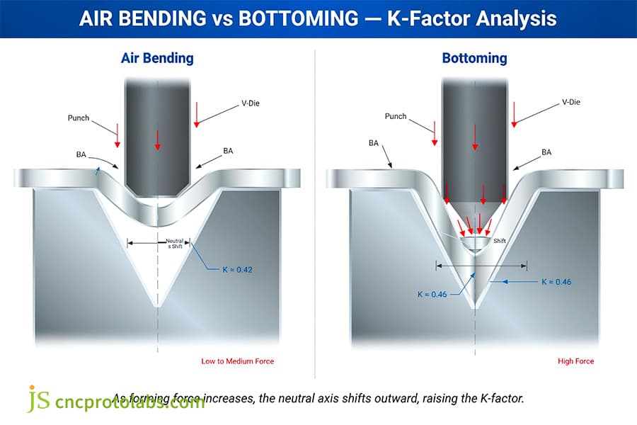
Figure 2: Diagram of force points and neutral layer position changes in air bending vs bottom bending.
Which Physical Factors Determine Sheet Metal K-Factor in General Fabrication?
In general sheet metal bending, the K-factor is driven mainly by the material's yield-to-tensile ratio and by sheet thickness. The typical question is what is the standard k factor for aluminum and steel; structural mild steel usually has K = 0.44 while for the 5052 or 6061 aluminum alloys it is usually 0.40 to 0.42. In higher-strength materials such as 304 stainless steel, resistance to compression on the inner face is significant, which lowers the K-factor to 0.36–0.38. The softer, more ductile 5052 aluminium reaches 0.40–0.43. Grain direction matters too: a bend made parallel to the rolling direction shifts the K-factor by ±0.03, so the offset has to be compensated explicitly.
Effect of the inner bend radius ratio (R/T)
- Sharp-corner bending (R/T ≤ 1.0): Strain is highly concentrated on the inner side, and the neutral layer shifts sharply to 0.30–0.33.
- Large radius bending (R/T≥4.0): The deformation distribution is uniform, and the K value is close to 0.50.
Material yield strength and grain orientation
- Low carbon steel (AISI 1018): tensile strength 440 MPa / yield strength 370 MPa, take 0.42-0.44.
- 304 stainless steel: tensile strength 515 MPa / yield strength 205 MPa, take 0.36-0.38.
- 5052-H32 aluminum alloy: take 0.40-0.43; 6061-T6 take 0.38-0.42.
- C11000 copper: Take 0.44-0.46.
- Grain orientation: When a sheet metal bent along the rolling grain is less workable, and the bending factor (K value) has to be lower by 0.02-0.03. The bending allowances are subject to tolerances ±0.03.
Bending tolerance control for various materials is dependent upon accurately made dies; consulting about metal stamping tooling tolerances often means a better unfolded dimension accuracy through the optimization process.
General Engineering Materials K-Factor Selection Criteria Table
The higher the material tensile yield ratio, the greater the compressive resistance on the inside, which forces the neutral layer to migrate more significantly to the inner surface, thereby reducing the baseline K value.
The values in this table assume air bending with a V = 8 × T die opening and R/T between 1.0 and 1.5. Your die width, punch radius and material batch will shift them — treat them as a first setup, not a final spec.
|
Material |
Tensile Strength (MPa) |
Yield Strength (MPa) |
Recommended R/T |
Baseline K-Factor (Air Bending) |
|---|---|---|---|---|
|
AISI 1018 Carbon Steel |
440 |
370 |
1.5 |
0.42‑0.44 |
|
304 Stainless Steel |
515 |
205 |
1.0 |
0.36‑0.38 |
|
5052-H32 Aluminum |
228 |
172 |
1.2 |
0.40‑0.43 |
|
6061-T6 Aluminum |
310 |
276 |
1.5 |
0.38‑0.40 |
|
C11000 Copper |
220 |
70 |
0.8 |
0.44‑0.46 |
According to ISO 7438:2020, metallic materials bend test specifications provide reference strain limits for K-factor determination.
See CNC sheet metal bending DFM guide for flange design rules that depend on the K-factor.
FAQs
Q1: Why does K-factor change with sheet metal thickness?
Difference in sheet metal thickness brings an alteration in K-factor because the amount of strain across the bend profile becomes unbalanced. As thickness increases from 1.0 mm to 6.0 mm, outer-fibre tension grows faster than inner-fibre compression, so the neutral axis moves further toward the inside radius to balance the internal moment. For example, 1.0 mm mild steel bent to a 1.0 mm inside radius gives K ≈ 0.44, while 6.0 mm of the same alloy gives K ≈ 0.38.
Q2: What is the standard K-factor for aluminum and steel in CAD software?
SolidWorks and Inventor default to K = 0.44 for mild steel formed in a standard V-die air bend. For commercial aluminium alloys such as 5052 and 6061, shop-measured values normally land in the 0.40–0.42 range. The usual source of error: these defaults get applied without checking the actual die opening (V = 8 × T), which can produce flat-pattern errors up to ±0.50 mm on thicker sections.
Q3: Can a sheet metal K-factor value exceed 0.50 in physical production?
Under standard air bending, the K-factor cannot exceed 0.50 — neither mathematically nor physically. A value of 0.50 signifies that the neutral axis sits precisely at the sheet centerline, representing pure elastic deformation with zero compression-induced cross-sectional thinning. In physical press brake bending, the inner material always compresses more readily than the outer material stretches in tension. If your calculation returns K > 0.50, suspect a measurement error in the test flange lengths, a wrong punch radius, or a bend angle entered in radians instead of degrees.
Q4: How does inside bend radius directly influence the final K-factor?
The inside bend radius governs how severe the deformation is in the bend zone. When the inside bend radius is much larger than the material thickness (R/T≥4.0), stress distribution becomes equal throughout the cross section, resulting in an increase of K-factor towards 0.50. Conversely, with a sharp bend (R/T ≤ 1.0), localized compressive strain pulls the neutral axis inward, reducing the effective K-factor to 0.30–0.33.
Q5: What distinguishes operational usage of K-factor and Y-factor fundamentally?
K-factor and Y-factor describe the same neutral-axis shift using different formulas. Most CAD systems use the K-factor (K = t/T); PTC Creo uses the Y-factor, where Y = K × (π/2). So K = 0.44 converts to Y = 0.691. Both locate the same neutral axis, but the two numbers are not interchangeable — entering a Y-factor where a K-factor is expected will produce the wrong flat pattern.
Q6: How do precision fabricators empirically verify an unknown K-factor on the shop floor?
Precision fabricators calibrate unknown K-factors by laser cutting a test strip of exact initial length (100.0 mm), bending the strip at 90°, and inspecting outer flanges with micrometers. Subtracting outside setback dimensions yields the actual measured bend allowance (BA). By inserting measured BA, sheet thickness T, and punch radius R into the formula K=(BA/(90×(π/180))‑R)/T, technicians derive the true shop-calibrated baseline.
Summary
Simply put: the K-factor is not a fixed constant. It is a responsive mechanical variable driven by material yield behaviour, tooling selection, and bend severity — which is why a value copied from a chart has to be confirmed with a test bend. The neutral axis shift is not a static constant, but a responsive mechanical variable governed by material yield behavior, tooling selection, and localized bend severity. Calibrating this factor across initial flat pattern drawings safeguards dimensional integrity, prevents scrap during secondary assembly, and eliminates trial-and-error downtime on the press brake.
For design engineers seeking to master advanced forming limits, tooling selection charts, and tight-tolerance flange calculations, explore our comprehensive technical resource: learn more about precision sheet metal bending at JS Precision.
Disclaimer
The contents of this page are for informational purposes only. For JS Precision Services, there are no representations or warranties, express or implied, as to the accuracy, completeness, or validity of the information. It is the buyer's responsibility to identify specific technical requirements and request a formal parts quotation. Please contact us for more information.
Resource

