 English



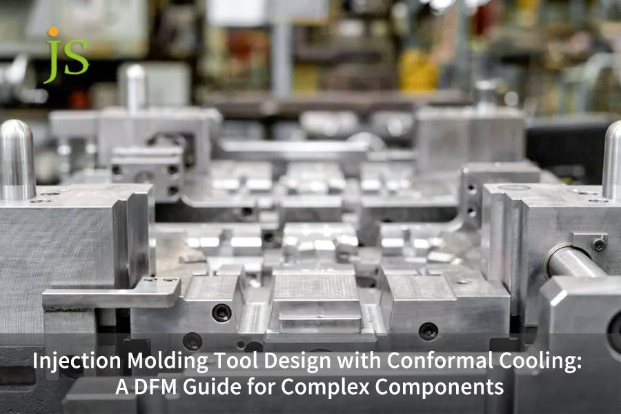

Conformal cooling mold design uses additive manufacturing to shape curved cooling channels inside mold inserts. These channels stay 2-5 mm away from the mold cavity surface. This makes the mold surface temperature difference ≤2℃ and cuts down cooling time by 20-40%, and with deep ribs, thickness changes, and complex curves, warping and shrinkage marks are eliminated.
This article, written from a DFM for injection mold tooling, introduces main design parameters, the coordination of channel layout with mold structure, material selection, simulation validation, and cost-benefit analysis.
Quick Overview of Core Parameters for Conformal Cooling Mold Design
|
Design Parameter |
Recommended Value |
Key Impact |
|---|---|---|
|
Channel-to-cavity distance |
2–5 mm (min 1.5 mm) |
Cooling efficiency + structural integrity |
|
Channel diameter |
6–12 mm |
Flow resistance vs. heat transfer area |
|
Channel spacing |
3–5× diameter (≈24–40 mm) |
Temperature field uniformity |
|
Cross-section shape |
Circular / teardrop / oval |
Circular = lowest flow loss; teardrop = +15–20% heat transfer |
|
Relation to parting plane |
≥3 mm offset from parting plane |
Prevent flash and seal failure |
|
Insert split strategy |
Split independent inserts by hot-spot zone |
Lower print cost, easier maintenance |
|
Seal structure |
O-ring groove, 15–25% compression |
Prevent coolant leakage |
Key Conclusions
- It is mostly the production volumes 50,000 units per year which trigger the ROI changes, unit cost reduction happens because cooling time is shortened.
- When the MS1 cavity channel distance is less than 1.5 mm, a structural failure is possible if injection pressure exceeds a value of >1,000 bar.
- In order not to be a problem for a user or factory, all kinds of conformal cool channels inside a mold must be made into their own blocks or segments and sealed properly.
- Channel design layout to be kept away from ejector pins, sliders, and the angled ones, it's one of the constraints which is easy to be overlooked when going through the DFM (Design for Manufacturing) phase.
Why Trust JS Precision’s Conformal Cooling Channel Layouts For Injection Mold Tooling Services?
Our team in injection mold making for automotive & medical fields has over 15 years of practical experience, and from that we have come to realize that the successful execution of conformity cooling mold design in Injection mold tooling needs three key stages with closed-loop feedback: DFM parameter definition, insert structure coordination, additive printing, and post-processing, instead of just relying on printing channels.
From our 3-month trial runs of Automotive sensor parts, we could see that the worst case was when water channel's 2.0 mm away from cavity, caused MS1 wall getting to 1.8 mm thick only at MS1, at 1200 bar, the stress was 1.1 times beyond the yield strength.
ISO 20457:2018 clearly states: Linear dimensional tolerances of precision plastic injection parts should match the dimensions range limits, and parting line sealing interference must be in acceptance parameters.
Drawing from this requirement, we decided to introduce ΔT≤3℃ and the O-ring compression ratio from 15 to 25% in our mold specs.
We managed to shorten the cooling period in an automotive sensor housing by 11 seconds, 32 sec to 21 sec, warpage reduced from 0.45 mm to 0.12 mm, and the scrap rate from 4.2% to 0.6%. Our approach to the project was eventually stored in the 212-project case data base of JS Precision.
Want to see conformal cooling case studies for similar complex parts? Contact the engineer to obtain the Conformal Cooling ROI Calculation Sheet, which includes templates for incremental costs, annual savings, and payback period.
How to Determine the Core DFM Parameters for Conformal Cooling Mold Design?
The main DFM parameters for conformal cooling mold design are channel distance from the cavity surface (2-5 mm), channel diameter (6-12 mm), and spacing (3-5 diameters). These four basic parameters set the level of the mold's cooling capability and its structural strength.
Cavity Distance is a Main Design Variable
- <1.5 mm: Heat exchange efficiency is extremely high, but DMLS printing of thin-walled steels may cause plastic deformation at injection pressures of 500-1,500 bar.
- >8 mm: Conformal feature disappears, becoming comparable with gun drilling.
- For pressure conditions greater than 1,000 bar, 4-5 mm is the right value, and for low-pressure conditions, 2-3 mm should be selected. Determining cavity offset from mold steel thickness and injection pressure is the initial step of DFM for injection mold tooling.
Channel Diameter and Spacing
- Diameter: This balances the heat transfer area and the mechanical strength of the component. A big channel gives more heat transfer and a better flow, but the amount of steel consumed is significant, <3 mm makes it almost impossible to remove powder. 6-10 mm is the range you will find suitable in most cases.
- Spacing: This influences the temperature evenness over the product. Too wide spacing, more than 5 times the diameter, results in thermal ridges, leading to a regular pattern of temperature differences on the product surface, too narrow spacing, less than 3 times the diameter, decreases the strength of the mold. The ideal is 3-5 times the diameter.
Cross-Section Shape Selection
- Circular: This gives the lowest flow resistance and the manufacturing is the most reliable.
- Teardrop (tip towards cavity): This shape will add heat transfer surface area by about 15-20%.
- Elliptical (the long axis of the ellipse is parallel to cavity surface): A halfway solution.
So, the offset and diameter of the channel can be said to be the foundation parameters of the conformal feature of cooling, a weak foundation will remain as such no matter how many times simulation is done afterward.
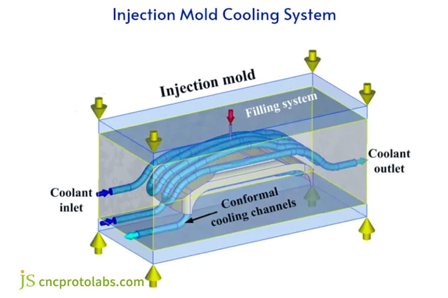
Figure 1: Conformal cooling mold design schematic with channels.
How to Coordinate Conformal Cooling Channel Layout with Mold Structure?
In the injection mold tooling service: when creating a layout for conformal cooling systems, Make sure to align the channel design with the parting line, ejector system, insert splitting plan, sealing structure at the Design for Manufacturability phase.
Channel and Parting Surface Separation
- Keep the distance between channel centerline and parting surface more than 3 mm to prevent molten plastic from leaking out to the channel through the high-pressure injected material.
- If the channel has to be passed through the parting surface, ensure both sides are provided with sealing structures.
Channel Layout and Ejector System
Ejector pins sleeves sliders, etc. are among the main causes of physical conflicts in channel layouts. With complex component mold tooling, the DFM stage is a phase during which the 3D channel overlay is checked for possible conflicts with injectors. A common set of approaches would be:
- Changing the ejector pin location.
- Routing the channel through the channel insert.
- Creating ejector pins with steps.
Splitting the Insert Strategy
Divide a conformal insert into a series of stand-alone modules in order that print costs can be controlled and repairs made easier. Splitting Principles:
- Splitting at the boundary of regions with high temperature.
- Ensuring the splitting surface has low stress level.
- Placing the water channel inlet/outlet outside each insert so pipes can be readily and accurately connected.
Sealing Structure
The mating surface between the insert and the mold is provided with an annular groove which gives a 15-25% compression of the seal. The water channel inlet / outlet use either a flat packing joint or a conically sealed joint. Should the sealing arrangement for the conformal cooling injection mold not be up to the mark, whole the mold would experience a sudden decrease in its cooling capacity without any notice.
Download the Conformal Cooling Channel and Ejector Pin Avoidance Checklist, which includes interference detection methods and sealing design points to help you avoid structural conflicts in advance during the DFM stage of complex component mold tooling.
How to Optimize Coolant and Rheology for Conformal Cooling Mold Design?
The optimization of cooling medium for conformal cooling injection mold focuses on three objectives: turbulent heat transfer (Re>4000), pressure drop control (Δ P<2-3 bar), and matching medium type according to resin temperature range.
Turbulent heat transfer condition:
The boundary layer impedes heat transfer in laminar flow. The Reynolds number Re is required to be greater than 4000, and Re is recommended to be greater than 5,000. The roughness of the inner wall of the SLM printed waterway (Ra ≈ 10 μm) reduces the actual effective Re, and a margin should be reserved in the design phase.
Pressure loss control:
Approximately 90 degree elbow bends contribute to the additional losses of 30-50% of the head. Techniques employed when it comes to flow resistance reduction up to 2-3 bar:
- Using of 90 degree bends is not suggested. It is better to make smooth bend radius > the diameter of the pipe.
- Use of multiple water channels in parallel.
- AFM smooths the internal wall so that it reduces the average roughness from Ra 10μm to 1.6μm(a reduction of flow loss is achieved by about 30 %).
Cooling Medium Selection
|
Application |
Coolant Type |
Temp Range |
|---|---|---|
|
Standard |
Water |
20–80°C |
|
High-temp resin (PC, PEEK) |
Mold heating oil |
80–200°C |
|
Low-temp application |
Ethylene glycol-water |
−10–20°C |
Injection mold design service often overlooks media selection—using room temperature water with PC/PEEK will cause condensation on the mold surface, introducing new defects.
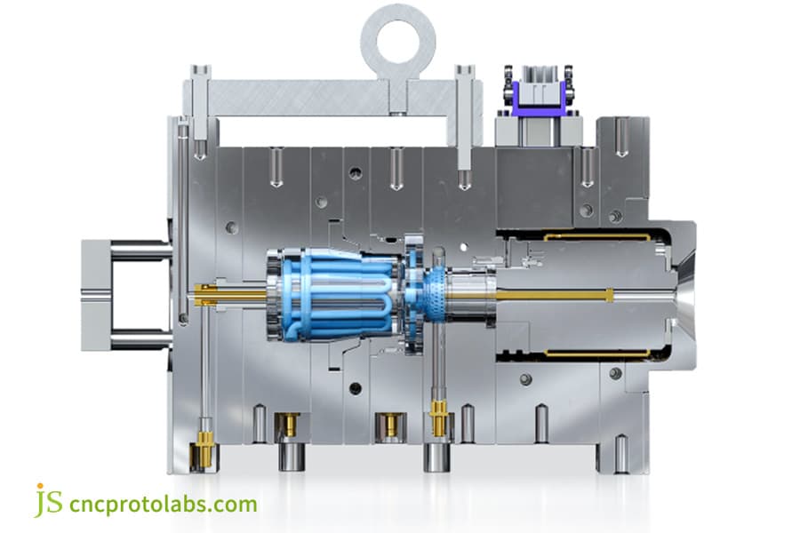
Figure 2: 3D model of injection mold with conformal cooling.
How Does Material Selection Impact Performance and Lifespan in Conformal Cooling Mold Design?
The material selection for the conformal cooling inserts of the high-precision mold service directly determines the mold life and thermal conductivity efficiency. Martensitic aging steel (50-54 HRC after aging, yield strength 1,100 MPa, thermal conductivity 17-20 W/(mK)) has become the most selected material for conformal coolant channel.
Comparison of Three Mainstream Materials
|
Material |
Hardness (post-HT) |
Yield Strength |
Thermal Conductivity |
Best Use Case |
|---|---|---|---|---|
|
MS1 (1.2709) |
50–54 HRC |
1,100 MPa |
17–20 W/(m·K) |
General conformal inserts |
|
H13 (printed) |
46–48 HRC |
~900 MPa |
24–28 W/(m·K) |
Not recommended for high impact |
|
CuCrZr |
28–32 HRC |
~400 MPa |
300–400 W/(m·K) |
Low-pressure, extreme cooling demand |
SelectionConsiderations:
- MS1: The printed state reaches 30-35 HRC after tempering at 490℃ it becomes 50-54 HRC, fatigue limit is 400-450 MPa - the magnitude of reversing stresses on the thinnest portion of the water channel should not be exceed this limit.
- H13: Printed state toughness is lower by about 40% compared to forged condition, not suitable for the situations with high impact load.
- Copper Alloy: Thermal conductivity is much higher - by a factor of 15-20 - than that of MS1, although the strength andare lower. It is ideal for the cases with minimal injection pressure and extremely high cooling demands.
- Hybrid Solution: Copper alloy inserts are used in the regions suffering the highest heat load whereas MS1 inserts go in the regions with structural stress.
In the context of conformal cooling, MS1+EOS M290 is currently the most mature process combination for custom mold tooling service.
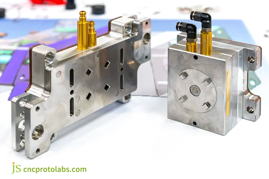
Figure 3: Metal mold components with brass connectors.
How Does Simulation Validation Identify and Eliminate Hot Spots in Conformal Cooling Mold Design?
After a complex component mold tooling conformal cooling channels have been printed, there is practically no opportunity in future to modify them so the design has to be simulated and validated before printing. Transient mold cooling analysis is carried out, usually with software like Autodesk Moldflow or Moldex3D, and this is a standard procedure.
Simulation Result and Hot Spot Removal
- Temperature Distribution Cloud Map: shows the cavity surface temperature difference.
- Temperature Gradient at Product Cross-Section: Demolding at a temperature of <15℃ is considered as satisfactory.
- Hot Spot Location: Thin ribs and thick boss areas are the ones most likely to experience hot spot issues since temperature discrepancies lead to non-uniform shrinkage, which in turn causes warping and shrinkage marks.
- Cooling Time Estimation: a comparison of traditional and conformal solutions.
Looped Iteration of Design-Simulation:
Preliminary layout → Moldflow analysis → hot spot annotation → waterway re routing → secondary verification → locked design, requiring 2-4 iterations to achieve ΔT≤3℃.
IATF 16949:2016 Quality Management System for the Automotive Sector, explicitly emphasizes: Special characteristics (like mold cooling uniformity) must be pinpointed and governed through the process FMEA.
Keeping this automotive mold control aspect in mind, we included ΔT≤3℃ and hot spot < mold temp +5℃ as special characteristics in a PFMEA document for the automotive Tier 1 sensor housing part, this was identified as the key reason behind the project's 94.8% first molds passing rate against only 62.5% for the other projects not having enough iterations.
In other words, for your automotive or medical complex parts, the number of simulations iterations will ultimately determine how likely it is that the mold trial is successful. You will hardly save enough time during the design phase to justify skipping one or two iterations whereas during the mold trial phase you will have to spend a much higher effort to recover the problems that have been left out.
Contact us for a free conformal cooling simulation verification report, Moldflow analysis for hot spots in your complex parts, and ΔT prediction and optimization suggestions within 48 hours to ensure the first-trial mold pass of the conformal cooling injection mold.
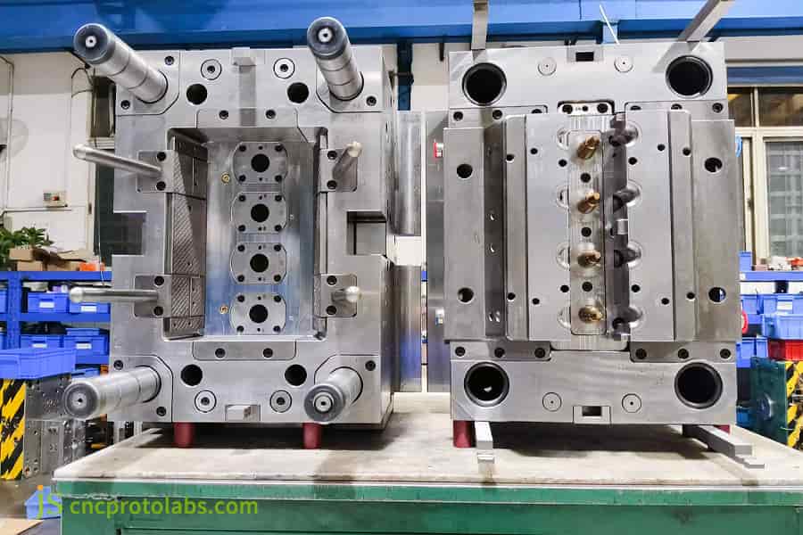
Figure 4: Large industrial injection mold in workshop.
How Did JS Precision Solve Warpage Challenges for an Automotive Sensor Housing Using Conformal Cooling Mold Design?
JS Precision developed and produced a conformal cooling injection mold for a Tier 1 automotive supplier's PC/ABS sensor housing. They achieved remarkable results - warpage was decreased from 0.45 mm to just 0.12 mm, while lots of time - cooling has been reduced from 32 seconds to 21 seconds and the scrap rate from 4.2% down to 0.6%.
Client’s Challenges:
Tier 1 automotive supplier has the need of developing a high-precision injection mold for an engine compartment sensor housing. The material was PC/ABS, features to mold include deep ribs (35 mm height/1.2 mm wall thickness), many bosses (8 mm diameter/12 mm height) and asymmetrical curved surfaces.
There are three primary problems with a conventional gun-drilled Class 101 water channel mold: cooling time takes the 32 minutes, total cycle time of about 46 seconds, this can barely meet one of the million yearly target, 18℃ temperature difference between the rib/boss regions, the warp from 0.38 to 0.52 mm due to temp difference (limit: 0.20 mm), and scrap rate of 4.2% with 73% of them are over warpage.
JS Precision Solution Key Steps:
- Mold Flow Analysis: Based on Moldflow analysis, there are three hot spots (two rib base of a deep one each and one the boss of thick).
- Insert Decomposition: Conformal area was split to three separate inserts with independent conformal loops, leading to a smaller print footprint and cost and it's easier to keep them up.
- Water Channel Layout: Three independent loops, size of 8 mm with channel distance of cavity of 3 mm, spacing between water channels of 28 mm (3.5x the diameter), a circular cross-section. Hot spots were covered spirally while the straight design was used for the remaining (non-critical) areas to cut the print cost.
- Mold Structure Coordination: Water channel design and ejector system were done together, CAD overlays ensured no interference between designs.The insert and mold base mating surface are designed with O-ring groove a 20% compression ratio.
- Additive Manufacturing and Post-Processing: MS1 was built with EOS M290, and tempered to 52 HRC at 490℃ for 6 h. AFM water channels were polished Ra1.6μm. Parting surface was wire EDMed. Conformal cooling from custom mold tooling service with AFM polishing Ra1.6μm was an essential step that guarantees water channels' longterm stability.
Key Decisions and Lessons Learned:
Initially, water channels were located at a distance of 2.0 mma from the cavity, which resulted in a MS1 insert with hot spot area wall thickness of 1.8 mm only. Structural simulations indicated that at 1,200 bar injection pressure the stress would be much higher than yielding strength of MS1 (1,100 MPa).The team decided to move offset to 3.0 mma, which meant about 8% cooling efficiency was lost Still structural integrity was ensured. This is one of the most common engineering trade-offs - prioritizing safety over efficiency.
Final Results (Data Anchor Points):
- Cooling Time: from 32 sec to 21 sec (-34.4%)
- Total Cycle Time: from 46 sec to 34 sec (-26.1 %)
- Temperature Difference: 18℃ to 3.2℃
- Warpage: from 038-052 mm to 010-014 mm
- Scrap Rate: from 42% to 0.6%
- At the yearly production of 1 million 2 parts, the downtime of injection moulding machine saves around 4,000 hours
The high precision mold service's real value comes not from getting as much as possible out of cooling stage of the part, but from identifying the best solution within structural boundaries of the product safety.
Are your complex parts also encountering warpage problems in deep rib or thick boss areas? Upload your 3D drawings (STEP/IGS) to JS Precision and receive a free DFM feasibility and ROI analysis within 48 hours.
How to Customize the Optimal Conformal Cooling Channel Layout for Your Complex Components?
Conformal cooling channel customization is done by following a five-step method: identification of geometric features, determination of hot spot locations, joint design of cooling channels and mold structure, printability check, and simulation iteration verification. JS Precision usually takes 8 working days.
Overview of the Five-Step Method
- Analysis of Geometrical Features and DFM Check:
Find out wall thickness distribution (areas with thickness >20 mm, thickness <1.2 mm), ratio of rib height to thickness, size of boss, cavity curvature, parting line. Concurrently, identify the positions of ejector pins and layout of parting.
- Accurate Location of Hot Spots:
Using the results of the Moldflow filling and cooling stage, one can determine the temperature map and the coordinates of hot spots. Areas where the temperature is above a certain level are designated as hard nodes that the Conformal Cool Channel has to handle.
- Design of Cool Channel Layout and Coordination of Mold Structure:
Develop the cooling channel network. At the same time, finalize the mold part layout, check for and avoid interference between ejector pins / sliders, design O-ring seal positions and after conformal cooling channel setup, finalize the insert and seal designing. The conformal cooling scheme of the injection mold design service must be completed synchronously with the disassembly of the insert and the sealing design, otherwise the rework cost in the later stage will be extremely high.
- Printability Check:
Each channel segment should be checked to comply with the minimum water channel axis angle of 45° to the print platform, minimum diameter narrowing down from a circle with a radius of at least 2 mm to 4 mm and bending radius 1 diameter. Otherwise, go back to step 3 for correction. At this stage, allowance for AFM post-processing is decided.
- Simulate a complete set of cooling simulations by transient state:
It is then input in Moldex3D or Moldflow. At least 5 full injection cycles should be done. Passing conditions are: ΔT≤3℃, hot spot < target mold temperature + 5℃ at product cross-section temperature gradient < 15℃ at demolding. It takes about 2-4 cycles to get the result.
Data Results
Based on 212 project data, standard processes were found to have the ability of passing a parts first time mold trial at 94.8%, decreasing average number of times design was iterated from 5.2 rounds to 2.3 rounds, and trimming the design cycle time from 3 weeks to 8 working days. For the conformal cooling design of complex component mold tooling, a standardized process is more dependable than people's experience.
Why Choose JS Precision as Your Conformal Cooling Mold Design Partner?
JS Precision is equipped with the entire production chain from DFM analysis, mold structure design, metal 3D printing (DMLS), to mold trial verification. It has delivered over 200 conformal cooling molds, resulting in an average of 28% less cooling time, 67% less warpage, and a 94.8% first-time mold trial pass rate.
Core Competencies
- End-to-End Closed Loop: Conceptual design → DFM analysis → Insert disassembly and mold structure design → DMLS printing (EOS M290/MS1) → Heat treatment → AFM polishing → Precision machining → Trial mold verification. A single vendor is in charge of the entire flow, minimizing coordination risks.
- Mold Design-Oriented Engineering Thinking: We first check the conformal solution from the viewpoint of an injection mold design engineer, the alignment of water channels with parting surfaces, ejection systems, and slide blocks, rather than just aiming for a geometrical perfectness of water channels. The solution is made to a degree that it can be practically installed and set into operation without any difficulty, and it is also able to keep working smoothly for a long time.
- Data-Driven Decision-Making: We present a real ROI forecast during the quoting phase based on 212 real-life projects, which included ABS, PC/ABS, PA66+GF, and PEEK materials, among others.
- Quantitative Commitment (Included in the Technical Contract): ΔT≤3℃, cooling shrinkage 20%, first batch trial mold pass rate (95)%, free revision is granted if not met.
JS Precision's goal when it comes to providing conformal cooling injection mold tooling service is not only limited to the production but rather to one-time mold trial success, which is an industry standard now.
Take Action Now: Send your 3D drawings (STEP/IGS), resin grade, annual production volume, and quality requirements to JS Precision to receive a free DFM assessment, ROI analysis, and detailed quotation within 48 hours.
FAQs
Q1: What is the approximate incremental cost of a Conformal cooling mold design?
The additional cost can be anywhere between $15k to $50k based on the complexity of the component, the number of insert molds, and the post-processing required. JS Precision will give a breakup of the costs during the quotation stage.
Q2: What is the typical payback period for a Conformal cooling mold design?
It is dependent on the annual production volume and the degree of cooling reduction. On a standard project, payback can be about 2.5 years with a yearly production of 50k pieces and about 1.25 years for 100k pieces.
Q3: Which resin materials are suitable for Conformal cooling mold design?
All thermoplastic resins can be used, even though the advantages are mainly for high-temperature injection grades like PC, PEEK, or PEI. The warping of these materials resulting from uneven cooling is significant and conformal cooling greatly increases the homogeneity of temperature as well as reduces scrap rates.
Q4: What is the minimum diameter for Conformal channels?
For direct metal printing the minimum feasible dimension is about 4mm. Water channels which are smaller than 4mm are harder to get powder out from and create too much pressure loss. Usually, JS Precision suggests channels of sizes 6 to 10 mm, larger size means more contact area for Heat Exchange but this will result in less structural strength that shall be taken into account.
Q5: Must Conformal inserts be separated into independent modules?
Splitting is advised. Modules reduce the amount of metal being produced at one time and its price, when it comes to damage sealing and/or replacing can also be easily done. Each module has a standalone circuit and can be divided along hot spot boundaries facilitating easier error detection and maintenance.
Q6: How to prevent cooling medium leakage in Conformal water channels?
Where the insert meets the mold the surface has an O-ring groove whose level of compression is maintained between 15% and 25%. For inlets/outlets Yet sealing flat sheets or conical seals are chosen.
Q7: How to handle interference between Conformal water channels and ejector pins?
There are three options: Move the ejection pin, make room in insert for cooling channel, or build a step pin. JS Precision employs CAD overlay check to find out any potential conflict at DFM phase.
Q8: How to get a quote from JS Precision?
Send your 3D drawings ( STEP/IGS ) with resin grade, annual production target and quality requirements to JS Precision within 48 hours we will perform a free DFM evaluation, ROI calculation and give a price. Besides, you can also directly upload your drawings and JS Precision will quickly reply with the quotation.
Summary
Conformal cooling mold design, through additively manufactured conformal channels, reduces injection mold cooling time by 20-40%, cavity surface temperature difference 2℃, and warpage by up to 90%. You will succeed when you rely on these six basics:
- Precisely defining DFM parameters (2-5 mm/6-12 mm/3-5 diameters).
- Synchronizing the channel-mold structure (avoiding parting surface/avoiding ejector pin/insert separation/O-ring sealing).
- Verifying the rheology (Re>4,000/ΔP<2-3 bar).
- Choosing an appropriate MS1 material (i.e. materials with minimal shrinkage after sintering).
- Carrying out a simulation closed-loop verification (2-4 rounds up to ΔT≤3℃).
JS Precision, with mold design engineer's view, offers the whole-process service ranging from DFM analysis and mold structure coordination, to DMLS printing and trial molding verification. Send your 3D drawings (STEP/IGS) and project scope to JS Precision now and within 48 hours, you will receive a free DFM feasibility assessment and quotation.

Disclaimer
The contents of this page are for informational purposes only. For JS Precision Services, there are no representations or warranties, express or implied, as to the accuracy, completeness, or validity of the information. It is the buyer's responsibility to identify specific technical requirements and request a formal parts quotation. Please contact us for more information.
JS Precision Team
Custom manufacturing solutions. With over 15 years of experience serving more than 1,000 customers, we specialize in high-precision CNC machining, sheet metal fabrication, 3D printing, injection molding, and metal stamping. Having successfully delivered over 300,000 precision parts, we maintain a 99.2% on-time delivery rate across all custom projects.
Our facility is equipped with over 100 state-of-the-art 5-axis machining centers and is ISO 9001:2015 certified. We deliver fast, efficient, and high-quality manufacturing solutions to B2B clients across 150 countries. Whether you require low-volume prototyping or large-scale customization, we support your project with lead times as short as 24 hours. Choose JS Precision for unparalleled efficiency, quality, and professionalism.
To learn more or submit your RFQ, visit our website: www.cncprotolabs.com
Resource

