 English





Overmolding service projects often encounter serious mass production bottlenecks when designers introduce complex undercut structures. This way, industry's main concern is how to both effectively prevent deformation and tearing of soft rubber elastomers and ensure smooth ejection of rubber-coated workpieces without defects. These issues lead to unwanted consequences like increased trash rate, higher mold modification costs, and delayed product launching when undercut design overmolding mold are not perfectly harmonized.
This paper not only reveals the hidden engineering skills and techniques in the sector but also outputs exact parameters and advanced slider demoulding mechanisms and offers practical overmolding solutions for undercuts that could enable ejection of workpieces without defects and achieve an ideal material fusion.
This article is going to break down the four main issues of projects in these way:
1.A microscopic stress concentration calculation method will be explained to help control the deformation of soft rubber and the strain at the interface while the parts are forcibly removed from the mold, mostly complex part ejection overmolding.
2.During the production of undercut tooling for overmolding, the sealing tape's exact parameters and the mold components' tolerances that are necessary to match and annihilate flash of low-viscosity elastomers will be given.
3.A case study of automotive industry high precision two-color component shows how JS Precision was able to make the problem of adhesive overflow a thing of the past by coming up with a new retracted bevel pin mechanism.
4.A theoretical analysis of the cost vs. benefit of a complex overmolding service project in which the rate of return on financial investment was taken into account has been used as the basis to compare the long-term comprehensive costs of a fully automatic core pulling mechanism and a forced removal solution.
Below will, step by step, help explain the process of converting high-risk overpressure molded structures into high-yield, high-precision mass-produced workpieces with professional undercut demoulding solutions.
Summary Of Core Answer: Overmolding Service Undercut Solutions
Choosing the best mold structure for each specific undercut type, setting the main technical parameters very tightly, and precisely matching the mass production requirements of different types of overmolded undercut components are the three main things that are needed to achieve efficacious overmolding undercut. Below, you will find a table outlining the top solutions for various undercut types as well as the scenarios they are suitable for.
|
Undercut Type
|
Tooling Mechanisms
|
Technical Parameters
|
Key Applications
|
Procurement Advice
|
|
External
|
Side-Action Sliders.
|
Lifter angle ≤ 25°. Mold opening stroke ±0.02mm.
|
Automotive door handles, Medical dual-color handles.
|
Suitable for high volume. Choose IATF 16949 certified manufacturers.
|
|
Internal
|
Lifters / Force Ejection.
|
Force ejection deformation ≤ 8%. Hardness 48-52HRC.
|
Electronic housings, three-way sealing parts.
|
Force ejection requires strict hardness control. Prioritize DFM risk assessment.
|
|
Complex Multi-directional
|
Hydraulic core pulling + Collapsible cores.
|
Core retraction speed 10-30mm/s. Shut-off land width 1.5-2.5mm.
|
Automotive connectors, medical device housings.
|
Require 5 axis CNC machining capability. Verify mold flow analysis.
|
|
Deep undercut
|
Two-stage mechanical lifters.
|
Lifter stroke 10-50mm. Locking force ≥120kN.
|
Industrial handles, sealing gaskets.
|
Choose suppliers with over 10 years of overmolding experience.
|
Key Takeaways
- Design optimization: For the over-pressure plastic undercut design, the slider or oblique pin mechanism should be given priority, and the slider splicing tolerance should be strictly controlled within ±0.01mm to prevent rubber lagging from flashing.
- Material ratio: The overlap depth between the hard substrate (e.g. PA66+30% GF) and the soft rubber (e.g. TPE/LSR) should be 1.5mm to guarantee the structural shear strength of the undercut.
- Procurement decision: Selecting a professional supplier who has ISO 13485 or IATF 16949 certification and providing overmolding tooling service is the best way to eliminate 95% of the hidden risks of ejection failure via DFM at the front end of the mold, also ensuring the molding accuracy and yield of overmolded undercut components.
Why Trust JS Precision's Overmolding Services? Expertise in Complex Demolding Solutions
With over 20 years of hands-on experience in complex overmolding mold release, JS Precision's engineering team has accomplished more than 500 overmolding service projects involving intricate undercut structures. To assure the highest quality of our work, we not only comply with the IATF 16949 automotive industry quality management system but also implement the ISO 13485 medical device quality management system in every project.
We drew on our encapsulation of medical equipment knowledge and at DFM stage with early intervention, we managed to reduce the customer's mold modification frequency by 1 from the usual industry average of 3-4, so greatly shortening the product launch cycle time.
During the design stage, our exclusive stress distribution calculation method of the mold design team accurately forecasts the demoulding resistance at the undercut to avoid mold trial failures later on.
We have top-notch precision processing equipment in the industry to hold the critical dimensional tolerance of the mold within ±0.005mm, which forms the basis for achieving zero flash lagging.
Our technical team not only boosts their knowledge of the latest mold design concepts and manufacturing processes consistently through attending international injection molding technology seminars but also undergo discussions and colloquia to become proficient in every new aspect of mold design and manufacturing technology.
Download our Overpressure Plastic Undercut Design White Paper to learn more about industry-leading engineering solutions and best practices.
Why Does Complex Undercut Design Become an Ejection Nightmare in Overmolding Service?
Complex undercut structures frequently result in parts getting deformed or even torn during overmolding service. All kinds of precisely overmolded undercut components are the first to suffer such mass production defects. One main reason is that the secondary heating of the two-color encapsulation produces a very strong adhesion between the two materials. If there is no accurate demoulding mechanism and the tolerance is not controlled, a local stress concentration will, without a doubt, lead to the destruction of the part's integrity.
Micro stress concentration mechanism
In comparison with a single-color injection molding process, rubber-coated undercuts undergo dual composite stresses from the base material and the soft rubber. In case of mold ejection, the soft rubber layer will experience tensile stress and shear stress simultaneously. If TPE is encapsulated with PC/ABS, the micro stress concentration factor Kt at the undercut will jump to more than 3.5, which is quite a bit higher than 1.8 for single-color injection molding.
Simply put, it is similar to a tiny cut in a paper, and the paper will rip from the cut if pulled gently. The notch where stress is concentrated is the sharp corner of the undercut.
Influences of Differences in Material Shrinkage
Soft elastomers usually have a shrinkage range of 1.5%-2.5%, while shrinkage of rigid substrates is only about 0.5%-1.0%. This shrinkage difference will result in an increase of holding force at the undercut, thereby making demoulding harder.
1. Initially, the soft rubber layer will firmly enclose the hard undercut.
2. Shrinkage differences can cause uneven stress distribution which results in stress concentration.
3. When the ejection stress exceeds the tensile strength of the soft rubber, tearing occurs.
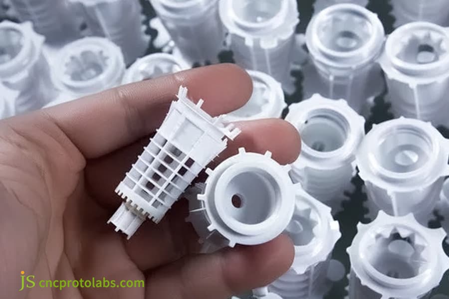
Figure 1: A hand holds a complex plastic part, showing a common ejection challenge in injection molding.
How to Optimize Complex Tooling Structures with Innovative Overmolding Undercut Solutions?
The key to implementing efficient overmolding undercut solutions lies in the actual planning of a very high-grade slider and bevel pin mechanisms. By merely regulating the oblique pin angle strictly between 3° and 15° and selecting mold steel 50HRC in hardness, it is possible to totally eliminate mechanical interference at the rubber coating undercut.
High-precision design of slider mechanism
The slider mechanism is the most common way to solve external undercuts, and its design precision is the main reason influencing the product quality. The slider fitting gap has to be consistently maintained within 0.005-0.012mm. If the gap is > 0.015mm, thin liquid soft glue can easily get through the gap in the presence of high temperature and pressure of 220℃, resulting in severe flash defects.
- Use inclined locking blocks to provide sufficient mold closing locking force.
- Precisely designed guide system ensures smooth movement of the slider.
- Hard chromium plating on the surface of the slider to improve wear resistance and service life.
Use of retracting oblique pin mechanism
The retracting oblique pin mechanism can be used for demoulding of internal undercuts. What it is that the ejection force drive the pin to recolapse inward to avoid the undercuts. Besides this, the mechanism has a compact structure and can save mold space.
- The oblique pin angle is normally maintained within the 8-12 range.
- The matching gap between the oblique pin and the template is kept within 0.008mm.
- Use of self-lubricating materials to reduce frictional resistance.
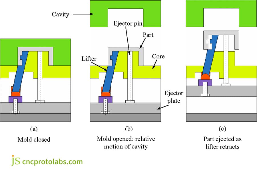
Figure 2: Diagram of mold opening process, showing core ejection and lifter retraction to handle undercuts.
How to Avoid Soft Rubber Tearing and Ejection Deformation During Complex Part Ejection Overmolding?
The main secret to dealing with soft rubber tearing during complex part ejection overmolding is to precisely balance the ejection timing and ejection area. Restricting the pneumatic ejection speed of the ejector plate to 50mm/s and making sure that the soft rubber is cooled down below the Vicat softening point are two things that can guarantee zero damage of the product.
Step ejection technology
Most opponents only advocate more ejector pins and neglect the interface shear strength between coating layer and the hard material substrate in the secondary coating(according to ASTM D2240 international hardness testing standard). JS Precision offers a technical solution by combining stepped ejection design with valve-assisted ejection, which can properly disperse the ejection stress.
1. The hard base material part needs to be ejected first so that the soft rubber layer is initially separated from the mold cavity.
2. Then the soft rubber layer should be gradually pushed out to prevent any sudden stress shock.
3. An air valve at the undercut area should be designed to allow compressed air for demolding assistance.
Parameter optimization of ejection system
Firstly, the ejection stress distribution varies Much when the hardness of soft rubber is at Shore A 40-80. Based on a lot of experimental work, the below key parameters are obtained:
1. The ejector pin contact area should be 35% larger than that of the conventional single-color mold.
2. The temperature of the substrate needs to be controlled at 40°C-60°C.
3. The ejection speed is supposed to be regulated as per the hardness of the soft rubber. The softer the rubber, the slower the speed.
Are you experiencing the high defective rate of rubber-coated products? Contact JS Precision for a dedicated DFM optimization report to improve the ejection system.
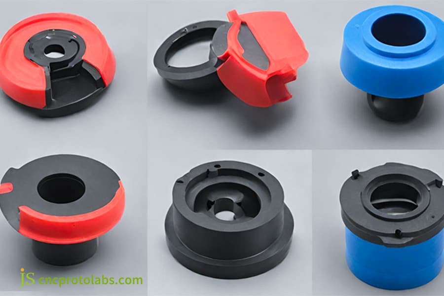
Figure 3: Multi-color overmolded parts designed for safe ejection, preventing tearing and deformation.
How to Efficiently Deliver Complex Overmolding Service Custom Projects Using Force Ejection Techniques?
Forced demoulding is a technique typically utilized in highly complex overmolding service, wherein the fulfilling of a particular ratio of undercut depth and elongation at break of the soft rubber is a condition. If the elongation at break of the soft rubber is 300% and the arc radius of the undercut part is 0.8mm, forced demoulding can be carried out even without any mechanism.
Forced demoulding geometric boundary conditions
Forced demoulding could be a great option to decrease the costs of molds and make overmolding service molding dimensions simpler. But, one has to perform very precise engineering calculations. JS Precision can reveal those geometric boundary conditions that necessitate forced demoulding:
- The ratio of undercut depth H to part diameter D should be 8%.
- The undercut leading edge should be formed as a progressive pin of 30°-45°, and a 90° right angle is forbidden.
- The undercut root should have a sufficiently large fillet radius, normally 0.5mm.
Forced release performance comparison of different materials
Various soft rubber materials exhibit differing properties for forced release. Below is a comparison of the main parameters of two materials which are most commonly used - TPE and LSR:
|
Material
|
Elongation at break
|
Maximum allowable deformation
|
Strain recovery rate
|
Recommended undercut ratio
|
|
TPE (Shore A 50)
|
300%-500%
|
≤8%
|
85%-90%
|
≤5%
|
|
TPE (Shore A 70)
|
250%-400%
|
≤6%
|
80%-85%
|
≤4%
|
|
LSR (Shore A 40)
|
400%-600%
|
≤15%
|
100%
|
≤12%
|
|
LSR (Shore A 60)
|
350%-550%
|
≤12%
|
100%
|
≤10%
|
How Does a Precision Manufacturer Control Tight Tolerances for Overmolding Tooling Service?
Controlling the very small tolerances in an overmolding tooling service require working with a machine tool with a very high precision and following a strict heat treatment process. By slow wire cutting and high-speed CNC processing, the dimensional tolerance of the undercut cavity can be secured to ±0.005mm.
Selection and heat treatment of mold steel
Generally, undercut tooling for overmolding fails because the mold steel is not heated properly which leads to a small misalignment of about ±0.03mm during the second molding, and that's why, the product gets scrapped. Professional and standardized overmolding tooling service will strictly control the steel heat treatment process.
JS Precision is highly selective in choosing top-quality mold steels like NAK80 or S136. These steels are vacuum quenched and tempered three times to make sure that the hardness level remains constant at 48-52HRC.
- NAK80 is pre-hardened steel and it is very easy to polish and work with.
- S136 is a stainless steel which is known for its great corrosion resistance and is perfect for manufacturing medically graded products.
- Heat treatment of the mold must be tightly controlled to maintain the dimensional stability of the mold.
Precision testing and quality control
We apply Zeiss coordinate measuring machine to the mold cavity to visually check during process so that the second injection molding sealing position will have a precisely measured glue amount of 0.02-0.04mm. Before each mold is shipped, strict mold and test procedures must be carried out to ensure that all dimensions are in line with the customer's requirements.
- Mold static assembly tolerance ≤±0.005mm.
- Slider motion repeatability ≤±0.003mm.
- Product key dimensional tolerance ≤±0.02mm.
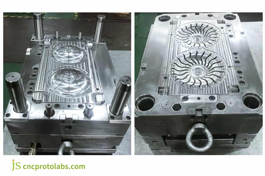
Figure 4: Metal overmolding mold with complex undercut cavities, used for manufacturing precise plastic parts.
How Did JS Precision Resolve a Flash Issue on an Automotive Dual-Color Slider by Rewriting Its Undercut Mechanism?
In the overmolding service of a vehicle-mounted intelligent two-color slider, JS Precision was able to upgrade the conventional side core-pulling slider to a combined retracted oblique pin mechanism that solved the major glue overflow problem of 0.2mm at the undercut of the slider.
Customer Problems
A first-tier auto parts buyer made a special rubber-coated slider for a car dashboard. The main material is PC+PBT, while the rubber-coated layer is TPU with a hardness of Shore A 65.
Due to the existence of an undercut with a depth of 3.5mm inside the product, the mold structure of the original supplier is unreasonable, and the mold springs back when the injection pressure is as high as 110MPa, causing serious glue running and overflow at the undercut, the thickness of the flash reaching 0.22mm, and the undercut breaking during ejection.
The customer has tried three mold repairs but failed to solve the problem, and the project has been delayed for two months, facing huge breach of contract compensation.
JS Precision Solution
Our engineering team simply took over and conducted DFM analysis from scratch again. Main steps are:
1. Eliminate the pneumatic side core pulling feature in the mold and replace it with a duct two-stage mechanical linkage retracting oblique pin mechanism that will be driven by the mold opening power of the injection molding machine, thereby completely removing the elastic deformation issue of the pneumatic mechanism.
2. To secure the undercut sealing surface with an extra 150kN mechanical locking force, when the mold is closed, a bevel locking block is used, so that in the high-pressure injection molding the sealing surface will remain sealed.
3. The sealing position mold preload has been modified accurately from 0.01mm to 0.03mm, and with the 5 axis CNC one-time processing it is possible to achieve a tolerance of ±0.005mm.
4. After improving the cooling system, the design of a conformal cooling water path was done inside the underturned core, and the cooling time was reduced by 12 seconds.
Failure Experience And Lessons
In the very first mold repair test, the flow channel pressure was too high cause local overcharging because the shear thinning feature of TPU under high pressure was not considered completely.
Then we firmly changed the plan and increased the gate diameter of the needle valve hot runner by 0.4mm, which nicely brought the peak injection pressure under control.
This experience indicates that when working with high-viscosity soft rubber materials, merely focusing on the mold structure is not sufficient, but one has also to adjust the injection molding processing parameters.
Final Result
The thickness of the flash at the undercut was completely eliminated from 0.22mm to 0.02mm (meaning no flash could be felt at all), the production cycle was reduced from 55s to 42s, and it successfully met the IATF 16949 automotive-grade appearance and size inspection standards at the first attempt. Product yield was drastically improved from the initial 65% to over 99.5%, thereby resulting in annual savings of over $120,000 in scrap costs to customers.
Customer Feedback
The purchasing director of the automotive supplier said: "JS Precision has revealed exceptional core engineering problem-solving abilities. It took only 21 days from the time we optimized the solution to the moment we received the first batch, which finally resolved the months-long project crisis. They are more than just mold makers, they are reliable technical partners."
Click here to submit your tough project and let JS Precision's experienced engineers customize overmolding undercut solutions for you.
What Cost Trade-Offs Must Engineers Consider When Selecting Overmolding Undercut Solutions?
To evaluate the cost-effectiveness of overmolding undercut solutions, it is necessary to quantify the ROI of initial mold investment and long-term production efficiency. By comparing the cost sharing of a single piece between the slider mechanism and the forced detachment scheme, it can help companies make the most commercially beneficial procurement decisions.
Mold cost amortization calculation method
We give here the seminal mold cost amortization calculation formula:
Single piece comprehensive cost = [Total mold investment (T) / Total output (V)] + Plastic coating processing fee per piece (U)
This expression is Mainly useful for finding out the real cost of various mold solutions for different production volumes precisely. In less technical terms, the smaller the output, the bigger the share of the mold costs, and the larger the output, the bigger the share of single-piece processing fees.
Cost comparison analysis of different options
One can see from the table below, which is an excerpt, that it points out the detailed cost of a single piece for different outputs for the forced release solution and the three axis fully automatic slider solution:
|
Production volume
|
Force ejection solution
|
Three-axis automatic slider solution
|
Cost difference per unit
|
Break-even point
|
|
10,000 units
|
$2.80
|
$4.20
|
+$1.40
|
-
|
|
50,000 units
|
$1.36
|
$1.64
|
+$0.28
|
-
|
|
100,000 units
|
$1.18
|
$1.22
|
+$0.04
|
~90,000 units
|
|
500,000 units
|
$1.04
|
$0.88
|
-$0.16
|
-
|
As can be seen from the table, when the output is less than 90,000 pieces, the forced removal solution has more cost advantages, when the output exceeds 90,000 pieces, the long-term cost of the three axis fully automatic slider solution is lower.
We not only optimize the design for you, but also help you control your budget. Contact JS Precision today for a customized two-way quote that combines processing feasibility and cost-effectiveness.
Why Choose JS Precision as Your Long-Term Partner for High-Difficulty Complex Overmolding Service?
With JS Precision as your manufacturing partner for complex overmolding service, you will receive end-to-end closed-loop support ranging from DFM front-end design, precision mold-making to batch overmolding production.
End-to-end process support
Our technical team is always at your disposal to deliver expert advice from the earliest DFM analysis to production ramp-up. Mold design, mold trial, and maintenance are only a couple of occasions where we intervene to keep the progress of your project on track. Our primary aim is to assist you in getting your product into the market rapidly with cost and risk kept at the minimum level without compromising.
State-of-the-art manufacturing capability
Our address is Humen Town, Dongguan City, China's manufacturing hub. Our plant is well-equipped with top-notch domestic and foreign precision manufacturing equipment, including Japanese Sodick slow wire cutting machines, high-speed precision spark machines, and multi-tonnage two-color injection molding machines. The production area is managed under 5S discipline to provide a neat and orderly workplace at all times.
Promptness and delivery before deadlines
We make a firm commitment to our customers: all progressive updates will be carried out with a thorough DFM appraisal and detailed quotation generation within 24 hours, whereas the lead time for samples is 7 days at the minimum. Being aware that time is a critical factor in product launch, we are continuously changing our operations and raising our standards to declare that your orders will be delivered on time or even before that.
FAQs
Q1: In overmolding service, what is the technical limit of allowable undercut depth?
The mechanical external slider can handle undercut depths of up to 50mm. If there's no demoulding mechanism, the depth of undercuts in soft rubber should be limited to 5%-8% of the part diameter and fillet 0.5mm, which are safe conditions to prevent part fragmentation and failure.
Q2: Will using undercut tooling for overmolding much increase mold manufacturing costs?
While this method can raise mold costs by 25%-40%, it's mostly caused by the expenses related to fitting a precision slider and the inclined pin mechanism. Besides, it can reduce defect rates by over 15%, and huge-scale production can make a big difference in saving scrap cost.
Q3: Why is it easy for flashing and glue overflow to occur in the undercut position when soft TPE is used to cover hard plastic?
The soft TPE molten glue has strong flowability, and inaccurate mold undercut fitting makes material easily leak and overflow. We apply 1.5-2.5mm sealing tape and control the tolerance of 0.005mm very strictly, which enables the flash problem to be solved in its origin.
Q4: What is the difference between liquid silicone LSR and thermoplastic elastomer in complex undercut molding?
The elongation at break of LSR reaches 400% -600%, and the deformation can be fully recovered by 12% -15%, with high forming fault tolerance. TPE deformation exceeding 8% is prone to whitening and permanent deformation, and has poor adaptability to complex folding.
Q5: Can you give me the quickest way of shortening the injection molding secondary cycle by the use of the optimized undercut design overmolding?
Changing the undercut design could bring a slider stroke reduction of up to 30%. The use of tailored core inserts and conformal cooling water channels increased the cooling efficiency by 25%, which is a very efficient means of decreasing the injection molding cycle time.
Q6: Which testing equipment does JS Precision use to ensure the factory pass rate when processing high-precision two-color rubberized undercuts?
At the mold phase, Zeiss three-dimensional coordinate machines are used to check the assembly tolerance 0.005mm. Industrial standards are followed by automatic optical images for large-scale production which are also a measure of strict product quality control.
Q7: For complex workpieces with internal undercuts, what advanced tool solutions are available to replace the slider?
When the external slider is prohibited, there are only two main options. First, the retractable oblique pin structure that pushes the out position, and second, the collapsible core that opens the mold and shrinks to adapt to the molding of complex workpieces.
Q8: We are in urgent need of rapid prototyping of a complex plastic-coated component. What is JS Precision's quotation and delivery process?
Clients may place the inquiry by sending 3D drawing and materials specification. We will give a free DFM report and quotation within 24 hours. Upon order confirmation, rapid prototyping cycle time is 7-10 days.
Summary
The key to addressing the problem of over-pressure plastic undercut is first accurate prediction of the DFM risk and finally effective control of the mold tolerance via precision. As slider, bevel pin retracting, and forced demolding all have something in common, tight sealing tolerance control and an optimized cooling system are the real factors that can jointly solve softer rubber tearing, ejection deformation, and rubber coating flash issues.
The combination of material characteristics, mold structure design and precision processing technology helps product appearance structure, mass production stability and economy is balance. JS Precision is well-versed in complex over-pressure molding projects and readily offers a range of services from design to mass production.
There's simply no need to go through costly cycles of testing and modifying molds. We utilize our technical expertise and well-established processes to roll out solutions for over-pressure molding products with high precision in mass production rapidly. Share your 3D files, and you will get a personalized DFM feasibility report and quotation within 24 hours, aiding product development speed.

Disclaimer
The contents of this page are for informational purposes only.JS Precision Services,there are no representations or warranties, express or implied, as to the accuracy, completeness or validity of the information. It should not be inferred that a third-party supplier or manufacturer will provide performance parameters, geometric tolerances, specific design characteristics, material quality and type or workmanship through the JS Precision Network. It's the buyer's responsibility Require parts quotation Identify specific requirements for these sections.Please contact us for more information.
JS Precision Team
JS Precision is an industry-leading company, focus on custom manufacturing solutions. We have over 20 years of experience with over 5,000 customers, and we focus on high precisionCNC machining,Sheet metal manufacturing,3D printing,Injection molding,Metal stamping,and other one-stop manufacturing services.
Our factory is equipped with over 100 state-of-the-art 5-axis machining centers, ISO 9001:2015 certified. We provide fast, efficient and high-quality manufacturing solutions to customers in more than 150 countries around the world. Whether it is small volume production or large-scale customization, we can meet your needs with the fastest delivery within 24 hours. Choose JS Precision this means selection efficiency, quality and professionalism.
To learn more, visit our website:www.cncprotolabs.com
Resource

