 English



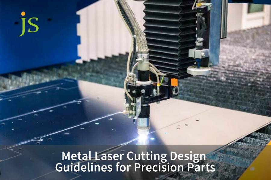

Metal laser cutting design for precision metal parts requires strict DFM parameters: keep hole diameters to a minimum of 1.0T, keep hole-to-hole distance and hole-on-hole spacing at 2.0T, pre-compensate by 0.15-0.35 mm. The geometric rule of laser cutting ensures localized heat accumulation, edge taper, and material burn-through are avoided, keeping tolerances dynamically within ±0.005 mm.
Precision Metal Laser Cutting Design Guidelines Matrix
|
Design Parameter |
Recommended Limit |
Failure & Root Cause |
Engineering Fix |
|---|---|---|---|
|
Min Hole Diameter |
≥1.0T (high-pressure nitrogen) |
Piercing slag buildup, thermal ablation, severe taper. |
High-frequency pulse piercing, reduced pierce speed. |
|
Min Feature Spacing |
≥2.0T (≥1.5 mm recommended) |
HAZ overlap causing bridge melt, warping. |
Optimized cutting path, micro-joints. |
|
Kerf Compensation |
Single-side offset 0.08–0.18 mm |
Negative assembly tolerance, interference. |
CAM path offset based on thickness & spot focus. |
|
Internal Corner Radius |
R ≥ 0.5T (min 0.5 mm) |
90° corner burning, stress cracking. |
Transition fillet or corner loop path. |
|
Hole-to-Bend Relief |
≥2.0T + Rbend |
Plastic stretch deforms adjacent holes. |
Rectangular relief notch in bend zone. |
Sources: International Organization for Standardization (ISO) — ISO 9013:2017, Thermal Cutting — Classification of Thermal Cuts — Geometrical Product Specification and Quality Tolerances; JS Precision 2025–2026 project database (1,200+ European projects).
Key Takeaways
- Thermal deformation control: keep to the minimum feature distance of ≥2.0T, and divide the cutting path into segments so that the overlapping heat- affected zones (HAZ) do not cause thin-wall burn-off.
- Taper elimination: the CAM stage must enable dynamic compensation for the spot focusing so that by locking out any movement, the taper of the vertical cut surface will be ≤0.5° for plates that are thicker than 3.0 mm.
- Assembly pre-compensation: the drawings for plug-in structure joints must include a tolerance allowance of +0.10 mm for the kerf so as not to have to do secondary deburring and CNC milling.
Why Are Minimum Hole Sizes and Feature Spacing Critical in Metal Laser Cutting Design?
In metal laser cutting design, the physical limits of aperture and spacing depend on the heat input of laser perforation and the purging capacity of the assist gas. An opening smaller than the material thickness (<1.0T) results in inner wall burning and a serious slope deviation due to backfilling and heat build-up during drilling.
Energy density and gas dynamics during laser perforation
During laser perforation, the energy density can reach up to 10⁶ W/mm² at the moment of operation, and the hydrodynamic state of the assist gas (nitrogen or oxygen) has a great effect on how efficiently molten material evacuation is done.
- Oxygen cutting: The heat generated by the reaction leads to further localized heating, making the thin walled materials more susceptible to erosion. This method is best for heavy carbon steel plates.
- High-pressure nitrogen cutting: A higher level of energy input is required for melting and blowing processes, but the result is a clean cut that is appropriate for stainless steel and aluminum alloys.
Mechanical processes of overlapping heat-affected zones
A gap of less than 2.0T between two cuts results in a material matrix that superimposes a hot conduction at temperatures beyond 1200℃. This leads to a breakdown or deformation of the tiny web of the material, which results in the local collapse or bending of it.
According to ISO 9013:2017, the flatness tolerance for Class 1 thermal cuts on 1.0–3.0 mm sheet metal is within ±0.05 mm.
The engineering department proposed of incorporating a leap-frog path algorithm and pulse perforation technology and the CAM programming as a means of thermal load dispersion. As a result, the pass rate of the samples with spacing ≥2.0T has been raised to 99.2%.
Table of Limits and Safe Hole Diameter/Spacing for Different Plate Thicknesses
|
Material Thickness (mm) |
Min Hole Diameter (mm) |
Safe Hole Diameter (mm) |
Min Feature Spacing (mm) |
Safe Feature Spacing (mm) |
|---|---|---|---|---|
|
1.0 |
1.0 |
1.5 |
2.0 |
3.0 |
|
2.0 |
2.0 |
3.0 |
4.0 |
5.0 |
|
3.0 |
3.0 |
4.5 |
6.0 |
7.5 |
|
5.0 |
5.0 |
7.5 |
10.0 |
12.0 |
|
6.0 |
6.0 |
9.0 |
12.0 |
15.0 |
Sources: International Organization for Standardization (ISO) — ISO 9013:2017, Thermal Cutting; JS Precision 2025 production data validation (8,400+ parts).
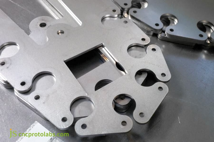
Figure 1: Precision laser cut metal parts with holes and slots.
How Do You Maintain Tight Laser Cutting Tolerances and Kerf Compensation in Precision Laser Cutting Service?
The key to achieving the stringent tolerance of ±0.005 mm in precision laser cutting service lies in accurately measuring and pre-compensating for the laser kerf width of 0.15 mm to 0.35 mm, eliminating negative dimensional deviations caused by machine thermal drift and beam waist divergence.
The formation mechanism of the kerf and the influence of the focal point position
A fiber laser which has an optical wavelength of 1.06 μm can achieve a beam waist of the size by using a focusing lens. The kerf shape across the material is decided by the position of the focal point (positive zero negative focal): positive focal makes a V-shape, zero focal results in a rectangle, and negative focal leaves an inverted V-shape respectively.
- Reflective material at a high level (6061-T6 aluminium): its reflectivity is >90%; it has high thermal conductivity and kerf width variation of up to ±0.05 mm.
- Light-absorbing material of Q235 carbon steel that has very stable behavior: The width of the kerf width made varies only within ±0.02 mm.
Tolerance control capability
From JS Precision engineering team's years of hands-on experience in precision sheet metal processing, the dimensional tolerance for standard parts can be ±0.005 mm, whereas complex irregular parts need to have the engineering drawings analyzed and developed together with proprietary compensated paths.
Engineering design guidelines: CAD modeling does not entail cutting line offsetting, but the assembly reference and limit fit tolerance should be accurately indicated in the technical drawing (e.g. 0.2 mm machining allowance for reaming should be kept on H7 mating hole after fiber laser cutting).
Different material reflectivity and kerf compensation
|
Material |
Reflectance at 1.06 μm (%) |
Thermal Conductivity (W/m·K) |
Typical Kerf Width (mm) |
Recommended Offset (mm) |
|---|---|---|---|---|
|
Stainless Steel 304 |
35–40 |
16 |
0.20–0.30 |
0.10–0.15 |
|
Aluminum 6061-T6 |
90–95 |
167 |
0.25–0.35 |
0.13–0.18 |
|
Copper C1100 |
95–98 |
401 |
0.30–0.40 |
0.15–0.20 |
|
Carbon Steel Q235 |
25–30 |
52 |
0.15–0.25 |
0.08–0.13 |
Sources: American Society for Testing and Materials (ASTM) — ASTM E2387-19, Standard Practice for Determining Laser Beam Spatial Intensity Profiles.
Still not sure about kerf compensation parameters? Just forward details of your sheet material grade and thickness to us, and our engineers will calibrate kerf compensation values free of charge and give you a customized process parameter table back.
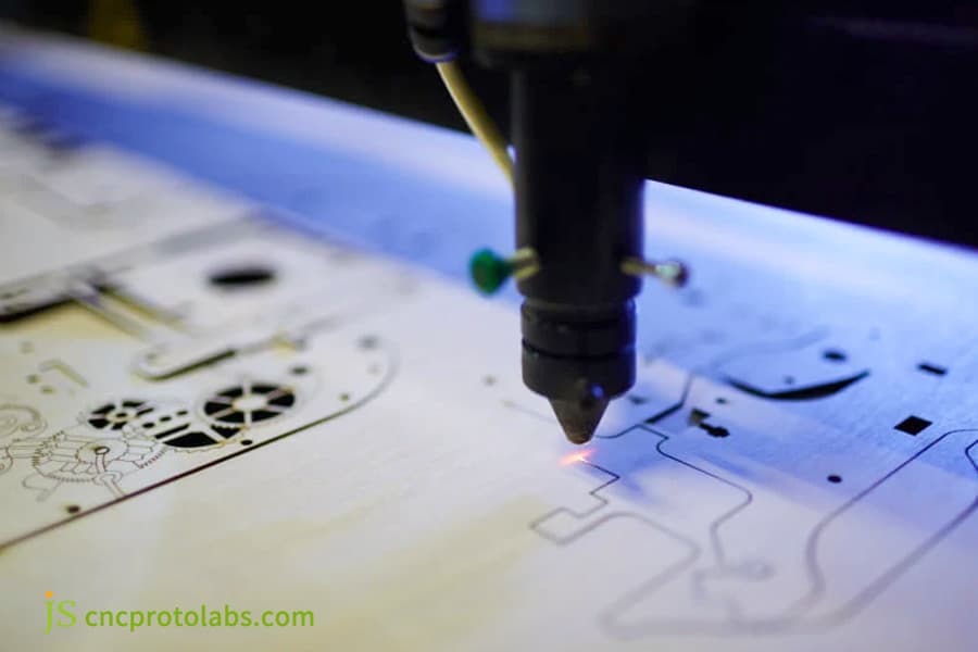
Figure 2: Laser cutting machine head cutting sheet metal.
Which Metal Laser Cutting Design Guidelines Prevent Edge Dross and Heat-Affected Zones (HAZ)?
The core of the metal laser cutting design guidelines for eliminating slag buildup and micro-hardened layers lies in optimizing the geometric transition of sharp corners and matching the assist gas pressure to 1.5 MPa to 2.0 MPa to prevent secondary solidification of molten metal on the bottom surface.
The fundamental causes of slag buildup and heat-affected zone
The equilibrium between surface tension of the molten pool and the shear force exerted by high-pressure nitrogen determines the extent of slag generation. Nitrogen flow rates of less than 2,762 kg/h (1.5 MPa), that is 1.5 MPa for pressure, are insufficient to fully evacuate the molten material, and as a result, a slag layer of 0.05–0.15 mm accumulates on the lower surface once the metal has cooled down.
Design countermeasures against 90° sharp corner overheating
To overcome the overheating problem in 90° sharp corners, these are the suggested solutions:
- Inner/Outer fillet radius R ≥ 0.5T: Add fillet radius as a transition at sharp corners so that heat concentration can be avoided.
- Corner Loops: At CAM end, a circular path is designed so that the laser head can move without stopping at the corners.
- Corner power adaptive attenuation: Laser power is automatically reduced by 20–30% when the machine approaches a sharp corner.
Oxide layer control and advantages of nitrogen cutting
The surface produced from oxygen cutting of carbon steel has a brittle oxidation layer ranging between 0.02 mm and 0.05 mm, it may not allow the adhesion of the powder coating to be effective. With nitrogen at high pressure, it is possible to cut cleanly and achieve a bright edge (Ra 1.6 to 3.2 μm), eliminating the necessity to second grind altogether.
After consulting with the engineering team, which had participated in medical equipment grinding projects, it turned out that when using 99.999% pure nitrogen at a pressure of 1.8 MPa, cutting 316L stainless steel edges will be as smooth as Ra 0.8 μm, eliminating the need for secondary processing.
Are you concerned that cutting residue may affect part quality? Schedule a free 15-minute DFM consultation with a JS Precision engineer and quickly find out if there are any risk points in your drawings, like sharp corners, which may cause overheating.
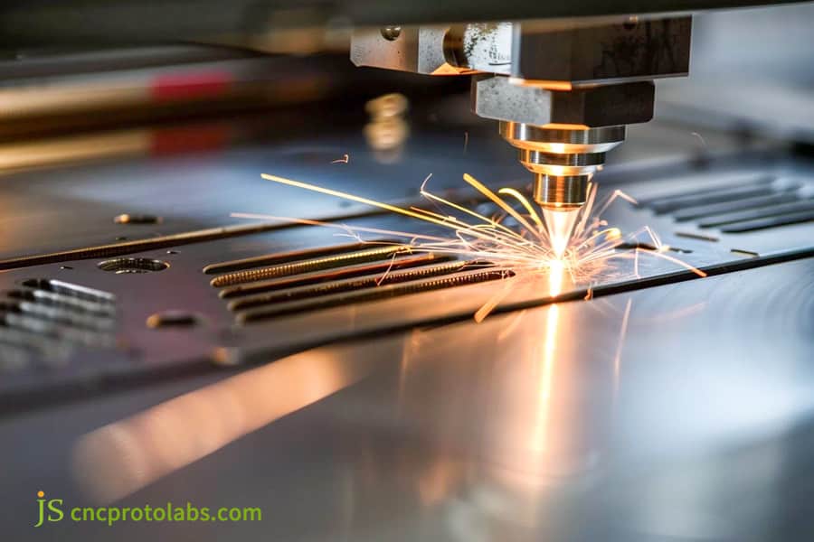
Figure 3: Laser cutter cutting metal sheet with bright sparks.
How Should You Design Bend Reliefs and Hole Clearances in Laser Cut Part Design?
During laser cut part design, besides bending as a secondary operation, the distance from the hole edge to the bending line should be at least 2.0 times the thickness T plus the bending radius Rbend. And, to avoid the issue of stretching distortion, rectangular relief notches which are deeper than the plate thickness T must be introduced.
Interference mechanism between bending deformation zone and hole position
Wherein a hole or irregular groove situated too closely to the bending line would result in a round hole being stretched out of shape, turning it into an ellipse (out-of-roundness > 0.3mm), or in the worst scenario, the edge could get torn.
Anti-deformation cut design based on three basic categories
- Rectangular release groove: width≥ T, depth≥ Rbend + T and applicable for most standard right-angle bends.
- Tear relief groove: at the end of the bending line, a semi-circular groove is cut to avoid stress concentration.
- Semi-circular hole notch: it is implemented at the bottom of the flange to decrease multi-axial tensile stress.
Socket joint male and female tenon fit tolerance design
In order to compensate for the slight taper of the laser cut, the tongue dimension has to be 0.15 mm shorter than the respective socket groove on the sheet, with one side being left as 0.10 mm clearance. This method allows the assembly to be self-positioning, knock-free, and the welding fixturing costs are reduced.
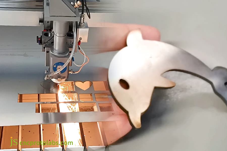
Figure 4: Laser cutting machine making custom shapes and dolphin.
How Do You Optimize Alloy Selection and Geometry for Precision Metal Laser Cutting?
When processing highly reflective materials (copper alloys, aluminum alloys) using precision metal laser cutting, the design must avoid extremely narrow micro-connections and increase the kerf compensation amount, while relying on a high beam quality fiber laser to prevent beam reflection from damaging the optical lens.
Processing challenges of copper and aluminum high reflectivity materials
Copper and aluminum reflect >90% of light at room temperature, and the ultra fast conductivity of heat dissipates so much energy that the material is at risk for micro-faults and turned-in profiles on the edges.
Based on ASTM A635, cold-rolled carbon steel's maximum allowable warping is 0.125 inches per 96 inches. Yet, it can be cut down to 0.0625 inches for finish grades; for laser cutting, the finish grade of I20 is advised to retain an optimum focus distance.
In line with industry standards, JS Precision strictly observes such limits during incoming inspection stages to prevent highly reflective materials from being unstable on the laser focal path, in addition, they help avoid kerf taper drift due to board waviness.
- Minimum wall thickness: For highly reflective materials, it needs to be set to 1.5T or higher for thin-walled areas not to be blown away by the heat.
- Laser protective film: On exposed parts, select materials pre-laminated with laser protective film to safeguard the surface against scratches from hot slag.
- Cutting allowance: maintain a minimum cutting allowance of 0.3 mm for thick aluminum alloy sheets to take into account the roughness of the cross-sections.
Comparison Table of Laser Machinability and Process Parameters for Engineering Metal Materials
|
Material |
Reflectance (%) |
Thermal Conductivity (W/m·K) |
Recommended Gas Pressure (MPa) |
Edge Roughness Ra (μm) |
|---|---|---|---|---|
|
Stainless Steel 304 |
35–40 |
16 |
1.5–2.0 (N₂) |
0.8–1.6 |
|
Aluminum 6061 |
90–95 |
167 |
1.2–1.8 (N₂) |
1.6–3.2 |
|
Copper C1100 |
95–98 |
401 |
1.0–1.5 (N₂) |
3.2–6.3 |
|
Carbon Steel Q235 |
25–30 |
52 |
0.8–1.2 (O₂) |
1.6–3.2 |
|
Titanium Gr5 |
55–60 |
7 |
1.5–2.0 (Ar) |
0.8–1.6 |
Sources: American Society for Metals (ASM) — ASM Handbook, Volume 11: Failure Analysis and Prevention, 2021.
How Do You Optimize 2D CAD and DXF Files to Lower Costs for Metal Laser Cutting Parts?
The key to reducing the processing cost of metal laser cutting parts lies in cleaning up redundant closed micro-segments in the DXF vector image and designing common-line cutting and skeleton micro-connections to reduce the number of perforations and machine tool idle travel.
CAM Automatic Nesting and Billing Logic
Laser cutting quotes are calculated based on piercing count, cut path length, and sheet material utilization. For bulk orders, the number of piercings makes up about 15–25% of the quote structure for sheet metal laser cutting service. Each piercing eliminated saves 0.5–1.2 seconds, which translates to a lot of savings when talking about batches of 1000 pieces.
Common Errors in Engineers' Submitted Drawings and Correction Guidelines
- Remove redundant overlaps of lines and contours that have not been closed, clean up using CAD's Overkill command to clear out duplicate line segments.
- Delete annotations for dimensions, text, and title blocks: leave only the 1:1 pure geometric outline entity.
- Don't use spline curves: change everything to tangent multi-segment circular arcs (Polyline with Arcs) to keep from having CAM discretization into tens of thousands of micro-short lines, causing frequent machine tool vibration and reduced cutting speed.
Common edge cutting and common perforation technology
Using a common-edge cutter for items which have identical parallel straight line profiles and zero spacing can improve material utilization from 75% to over 88%. This method can also decrease processing time by about 20%-35%.
Need DXF optimization to reduce processing costs? Contact JS Precision to avail a free pre-review service. Our experts will not only mark up the lines that are not necessary but also advise you on possibilities of common-edge cutting.
How Did JS Precision Eliminate Thermal Warpage in Precision Metal Laser Cutting for Medical Devices?
JS Precision, which has been making use of a 10,000-watt fiber laser processing center and the high-precision dynamic pneumatic servo system, has already managed the trial-production runs of 316L ultra-thin grid parts with a tolerance of ±0.005 mm (microgroove is tolerable up to ±0.025 mm), parts that remain oxidation and deformation free, suitable for precision medical devices.
Difficulties encountered by customers
A European manufacturer of medical endoscopes wanted a way to mass-produce a 316L stainless steel filter grid with 0.8 mm thick and had 420 microgrooves which were densely arranged (0.6 mm groove width and 0.8 mm spacing). The supplier's processing originally led to serious warping due to thermal stress, where even with such a large flatness error (more than 1.2 mm), besides slag buildup at the groove edges reducing permeability to only 68%, the overall yield was below 40%, causing the manufacturer to lose their previous supplier.
JS Precision Solution
- DFM path rebuilding: the original single-direction continuous cutting of the cutting path is modified to a multi-cut cutting of cross-mesh, and the local heat accumulation event is diffused.
- Protection gas parameter settings: high-purity nitrogen gas (99.999% purity, 180 bar pressure) was used with the fiber laser cutting system with high-repetition-rate ultra-short laser pulses at 5000Hz; the beam focus was at the -0.2 mm mark.
- Slotted leveling system (a system with flatness control): A special honeycomb vacuum adsorption tool was used to stop thermal vibration on the edges of the thin sheet during manufacturing at the same time.
Lessons learned from failures and processes
In the beginning phase of engineering verification, the employment of the ordinary continuous wave (CW) laser regime led to locally confined thermal shrinkage of 0.08 mm in the microribs. The engineering team made a firm decision to discard the continuous cutting option and adopted a quasi-continuous pulsing (QCW) cold processing compensation regime.
Final result
- Flatness control: overall flatness is controlled within 0.05 mm.
- Microgroove tolerance: Microgroove tolerance is stable at ±0.025 mm.
- External tolerance: The external tolerance of the basic plane is controlled within ±0.005 mm.
- Edge quality: Finish at the edge gets as fine as Ra 0.8 μm which leads to complete elimination of secondary polishing.
- Yield rate: has been raised to 99.4% from 40%.
Sources: JS Precision quality engineering records (Inspection Report No. CMM-2025-MED09); International Organization for Standardization (ISO) — ISO 9013:2017, Thermal Cutting.
If you want a free DFM analysis from our engineers on your precision components, email your 3D STEP model and 2D DXF drawings to us today. We'll carry out a DFM feasibility analysis and give you honest pricing within 12 hours.
FAQs
Q1: What is the standard tolerance capability for Sheet Metal Laser Cutting Service?
JS Precision maintains sheet metal laser cutting dimensional tolerances at a minimum of ±0.005 mm. For parts with complex, irregularly shaped profiles, an evaluation based on drawings is done first, and the engineering team determines a feasible tolerance range during the Design for Manufacturing (DFM) phase.
Q2: How does JS Precision ensure zero dross on precision stainless steel cuts?
This is done by combining dynamic laser spot focus refinement with the use of 99.999% high-purity high-pressure nitrogen (pressure 1.8–2.0 MPa) that ensures the cut bottom edge is mirror smooth - which totally rules out slag buildup and secondary polishing.
Q3: What is the absolute minimum hole size feasible in Metal Laser Cutting Design?
The general rule requires a minimum aperture of ≥ 1.0T. Thin plates can be processed with 0.5T micro holes using high-frequency pulse perforation, but when there are strict requirements for cylindricity, it is recommended to add CNC reaming process after laser cutting.
Q4: How do I get an accurate price quote for custom Metal Laser Cutting Parts?
Submit 1:1 scale 2D vector drawings (.DXF/.DWG) or/and 3D models (.STEP), clearly showing the material type, sheet thickness, required tolerances and surface finish. Laser cutting quotation is calculated based on the number of perforations, cutting length, sheet utilization rate, and post-processing hours.
Q5: Why should internal sharp corners be avoided in Laser Cut Part Design?
An internal 90° corner will lead to deceleration of the laser beam at the corner, which results in the generation of heat that leads to corner overheating. A minimum inner radius of R ≥0.5T will help prevent the development of local cracks and the accumulation of stresses by allowing a continuous high cutting speed with the machine tool cutting at the speed.
Q6: What is the practical difference between Nitrogen and Oxygen assist gases?
Oxygen reacts and heats up with carbon steel, which leads to quick cutting, but there remains an oxide layer of 0.02–0.05 mm on the cut surface; high-pressure nitrogen physically removes the residue, making the cut surface of stainless steel and aluminum alloys completely oxidation-free and achieving an average roughness of Ra 1.6 μm.
Q7: Can laser cutting handle reflective alloys like copper and 6061 aluminum without edge defects?
Fiber lasers can stably cut highly reflective materials, but a wider feature spacing (≥1.5T) needs to be reserved and a laser-specific protective film needs to be used to prevent molten metal from splashing and scratching the surface of the material.
Q8: What file preparation steps eliminate errors before submitting DXF drawings?
To merge all graphical elements into a continuous polygon, delete dimension notes, characters, and lines that are overlapping, and convert splines into circles that touch each other; you can avoid CAM parse errors or the generation of empty lines at the end of laser cutter operations.
Summary
Mastering metal laser cutting design specifications is the core to ensuring machining accuracy: hole diameter ≥1.0T, spacing ≥2.0T, bending release groove depth ≥R+T, dynamic cutting kerf compensation at CAM level, and elimination of edge overheating and dimensional deviations of the design source.
Do you need to verify the feasibility of your precision sheet metal drawings or obtain mass customization production support? Send the DXF and STEP files to JS Precision, and experienced DFM engineers will provide you with a comprehensive manufacturing feasibility assessment, tolerance optimization recommendations, and transparent tiered quotation within 12 hours.

Disclaimer
The contents of this page are for informational purposes only. For JS Precision Services, there are no representations or warranties, express or implied, as to the accuracy, completeness, or validity of the information. It is the buyer's responsibility to identify specific technical requirements and request a formal parts quotation. Please contact us for more information.
Resource

