 English



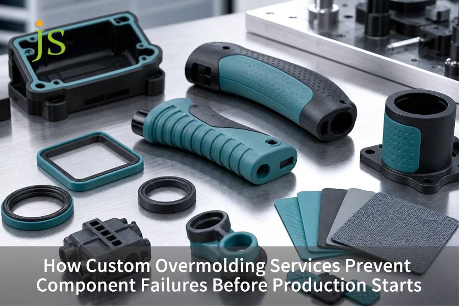

Custom overmolding service prevents component failure before mass production starts by analyzing mold flow, material matching, and sealing design, locking interface strength and size, reducing the industry average 15% trial mold scrap rate to zero, avoiding mold modification costs, and shortening the market cycle by 4 weeks.
The ensuing sections, which present technical specs and control matrices of the process will show how to eliminate defects in the overmolding process quantitatively without having to open the steel mold!
Custom Overmolding Service Failure Prevention Matrix
|
Failure Mode |
Root Cause |
JS Precision Prevention Spec |
Bonding Mechanism |
|---|---|---|---|
|
Delamination |
Insufficient interfacial thermal energy, weak molecular entanglement |
ΔT ≥ 30°C, mold localized heating to 80°C-110°C |
Chemical bonding (polar attraction) + primer coating |
|
Substrate Meltdown |
Excessive melt temperature or thin substrate wall |
Substrate wall ≥ 1.5 mm, injection pressure ≤ 120 MPa |
Thermal support + uniform wall design |
|
Flash |
Insufficient shut-off contact pressure |
0.05 mm interference fit, seal-off width ≥ 1.5 mm |
Micron-level hard seal physical cutoff |
Key Conclusions
- Material thermal compatibility: The hot distortion point of the first material should be at least 30℃ higher than that of the molding injection temperature of the second material to prevent deformation after double-shot.
- Structural solution: With bond failure between two materials, a mechanical reinforcement is provided through dovetail slots having depth 0.5 mm and an angle of 45°-60°.
- Zero flash sealing: A sealing channel having width 1.5 mm is positioned along the edge of the overmolding which together with the clamping strength of the mould prevents molten plastics from overflowing.
Why Trust JS Precision’s Custom Overmolding Service To Prevent Failures?
Our group has a 15 years long-standing know-how of multi-component injection molding, so based on that, to be sure the overmolding does not fail, a custom overmolding service should have three basic capabilities: mold flow analysis, interface material compatibilities, and tight mold tolerances.
It's stated in ISO 10993:2018, Biological evaluation of medical devices, in vitro cytotoxicity tests: All materials for long-term tissue contact should cytotoxicity test and no leachables should be present at the interface.
To comply with the regulation exactly as outlined, we only work with medical-grade LSR or TPU in medical overmolding, and we maintain the substrate interface roughness under Ra 1.6μm. The specification is checked by subjecting the material to several cycles of sterilizations at 134℃.
For a European endoscope handle project, the first solution led to 18.5% peel failures. By a change in the manufacturing process to a two-component injection molding method at the same time, we used the hot substrate at 140℃ to initiate molecular bonding. The peel strength increased to 8.4 N/mm from 2.1 N/mm, and the output went up to 99.8% thanks to the dovetail grooves and staged filling five times.
Want to assess whether your overmolding design has a peel risk? Contact our engineers to obtain the Overmolding Failure Prevention Self-Checklist, which includes a ΔT matching table and recommended dovetail groove dimensions to proactively avoid mass production defects.
How To Maximize Interfacial Bond Strength In Custom Overmolding Service?
The main factor in boosting the bonding strength of the second injection mold is getting molecular chains of the two materials at the interface to diffuse with each other and covalently bond. When the softening point and the polarity of a rigid substrate and a flexible adhesive are perfectly matched, the interfacial shear strength can be higher than the tensile limit of the material itself by many times and, that means, fully prevent delamination. The essence of overmolding material bonding service is welding at the molecular level.
Bonding Energy Differences and Polarity Matching:
Bonding energy among different material pairs is highly variable. For custom overmolding, the first priority is polarity matching:
- TPE/TPU and PC/ABS/PA66: Same or comparable polarity, interfacial shear strength > 6 N/mm.
- TPE and PP(non-polar): Bonding energy<2 N/mm, use mechanical interlocking reinforcement.
- Covestro and other resin grade matching data: The best solution for custom TPE with maleic anhydride is graft (MAh) that is, increasing covalent bond by 3 x times, is recommended.
Second Injection Timing and Surface Preheating
A critical factor of the time window in a two-phase injection molding:
- Within 4 hours after the formation of the substrate: The second injection molding over the substrate must be made to expose and trigger the latent or hidden cross-linking reactions of the substrate using its residual heat.
- After 4 hr: Substrate surface needs to be preheated to 120℃ to prevent the strength of the interface from shearing to drop 40%.
The overmolding material bonding service and the process window determines the bonding performance in mass production.

Figure 1: Green and transparent overmolded phone cases showing material layers.
How To Utilize Overmolding DFM Service To Prevent Substrate Deformation?
During the overmolding process, the high-pressure, high-heat molten material secondary injected into the mold cavity easily leads to the local abrasion, melt, or thermal stress deformation of the primary rigid substrate. The dimensional stability in mass production is guaranteed by the geometric optimization of substrate wall thickness, reinforcing rib location, and gate design through the normal DFM service. The essence of the overmolding DFM service is wall thickness balancing.
Wall Thickness Design and Shrinkage Calculation
One direct way the risk of warpage gets controlled is by balancing the size of the rigid substrate and overmolded overlay.
- Rigid Substrate Wall Thickness: This thickness must be kept in the range of 1.5 mm to 2.5 mm to be abrasion resistant enough.
- Overlay Thickness: Its thickness must be kept below the rigid substrate wall thickness but between 1.0 mm and 3.0 mm.
- Total Shrinkage Calculation: Total Shrinkage = Substrate Shrinkage + (1 - α ) Overmold Shrinkage (where α is the volume percentage of the substrate).
Wall Thickness Reduction and Reinforcement Ribs Spacing
Warpage-free methods through DFM optimization:
- Thickness removal means making sure there are no thick-walled areas and because of this reduce weight, making the wall thickness even, and keep the shrinkage difference in between as a minimum of 0.1%.
- Reinforcement Ribs Spacing: P ≤ 3 × Thickness, offering anisotropic shrinkage resistance.
Utilizing our overmolding DFM service allows engineers to detect potential warpage hazards prior to final detailing, successfully eliminating costly post-mold modifications.
Upload your drawings with one click to get a free DFM report. Our engineers will provide wall thickness optimization and gate location suggestions within 24 hours, locking in deformation risks from the source.
Why Strict Overmolding Process Control Is Mandatory To Eliminate Flash?
Overmolding flash typically results from lack of sealing pressure at the point of closure of the mold or first injection tolerances that are too wide. Only by using closed-loop two-injection process control and precisely regulating the injection pressure, speed switching points and mold clamping force, is it possible to achieve micron-level perfectly smooth burr-free edges. The central point of overmolding process control is sealing interference.
Mold Sealing Point Design Specifications
One of the key reasons why JS Precision's sealing control is so good is the combination of three different factors. Mold design parting line interference is not something decided at convenience without justification for injection molded parts as it turns out.
Per the ISO standard ISO 20457:2018, Plastic products, Tolerances and acceptance of injection molded articles, it says, tolerances for the linear dimension of precision injection molded articles must be specified in correspondence with the dimensional limits, and at the same time the fitting of the mating surface must be considered as one of the acceptance parameters for the molded part.
This standard has been fully adopted by us, so that we are keeping the parting line interference tight to a range of 0.03 - 0.04 mm with interference surface width 1.5 mm. The high-pressure injection will be prevented under a second injection pressure of 120 MPa by a 150-ton fully electric clamping force. In detail:
- Parting line interference fit: The mold steel parting line should have a localized mechanical interference fit of 0.03-0.05 mm to clasp the first shot part.
- Gradually decreasing speed: As the melt flows through the sealing edge, shear rate should be reduced to prevent sudden viscosity losses causing flash.
- The Second Shot Holding Pressure: The second shot pressure must be held to 70% or less of the first shot clamping pressure to prevent tearing of the substrate bonding surface by pressure.
Process Parameter Control Essential Points
- Sealing Interference: A typical recommended value would be 0.03 - 0.05 mm. Anything less than 0.03 mm leads to flashing and over 0.05 mm crushes the substrate.
- Second Shot Pressure: 70% of maximum of clamping force first shot. Going beyond results in deformation of the substrate.
- Shear rate: Shear rate should not be higher than 40,000 s. Otherwise melt fracture will probably take place that leaves a serrated appearance along the surface.
The accuracy of overmolding process control has a direct effect on the consistency of the product outer look and physical measurements.
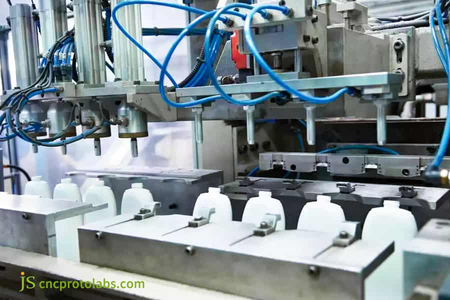
Figure 2: Automated injection molding machine producing plastic bottle caps.
How Do Mechanical Interlocks Ensure Defect-Free Overmolding Failure Prevention?
When the different materials are not chemically bonded, mechanical interlock is the main physical barrier against shear forces and it prevents edge peeling. By manufacturing substrates with undercuts, through holes, or dovetail grooves one can realize a strong physical interlock, which forms after the melt has solidified. Mechanical locks for the overmolding failure prevention are very design-sensitive. Their efficiency depends on the precise choice of the geometrical shapes.
Microscopic Geometry of Three Types of Mechanical Locks
The interlock design standards of JS Precision are as follows:
- Dovetail Groove: A 45° to 60° cut, depth of at least 0.8 mm, used mainly against the pull-out forces.
- Through Hole: Diameter of the hole ≥ 1.5 mm, the hole edge has been designed with a 0.5 mm×45° chamfer producing a double-sided rivet effect.
- Edge Ribs: Spacing is P ≤ 3 × Thickness. This brings anisotropic resistance to shear forces.
Interlocking Geometric Parameter Comparison Table
| Interlocking Type | Critical Dimension | Pull-out Force Enhancement | Applicable Scenarios |
| Dovetail Groove | Angle 45°-60°, Depth ≥ 0.8 mm | 300% | Handle, Grip Area |
| Through Hole | Diameter ≥ 1.5 mm, Chamfer 0.5×45° | 250% | Panel, Housing |
| Edge Ribs | Spacing P ≤ 3T | 180% | Large Area Overmolding |
Mechanical locks with overmolding failure prevention are the last line of defense against chemical bonding failure.
Contact us to obtain the interlocking design CAD standard part specification file, directly import your design drawings, and ensure the mechanical lock geometry parameters are accurate from the start.
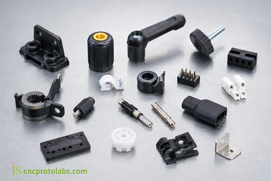
Figure 3: Various plastic and metal components for overmolding applications.
How To Predict And Eliminate Gas Traps With Advanced Mold Flow Analysis?
Molded secondary melt propagating over a rough rigid surface could bring trapped gas at the end of the overmolding or wall thickness changes if the venting is not properly designed. Dynamic simulation using Moldflow software, the simulation tool, helps locate venting blind spots and so solve problems of venting in mold opening before opening the mold. The flow analysis of pre-production overmold testing is the core means of preventing trapped gas.
The Mold Flow Analysis Boundary Conditions
JS Precision's mold flow simulation parameters are:
- Initial first material part temperature to a solid inserted substrate set at 40℃-60℃ for an accurate heat flow between material layers.
- Optimizing the volume shrinkage rate and cavitation distribution to choose the proper second injection gate position so that final filling point is at the mold parting surface.
- Venting groove depth is tightly controlled at 0.015mm to avoid TPE material leakage besides venting only.
Main features of the Venting Design Parameters
Various venting techniques A lot differ in their applicability and efficacy:
- Parting Surface Venting Groove: groove depth 0.015 mm, suitable for TPE/TPU materials, venting efficiency up to 95%.
- Spacer Venting: groove depth 0.02 mm, suitable for LSR materials, venting efficiency around 90%.
- Vacuum Assisted Venting: grooveless venting, all materials, venting efficiency up to 99%, calls for higher capital equipment input.
The flow analysis of pre-production overmold testing can expose over 90% of trapped gas risks in advance.
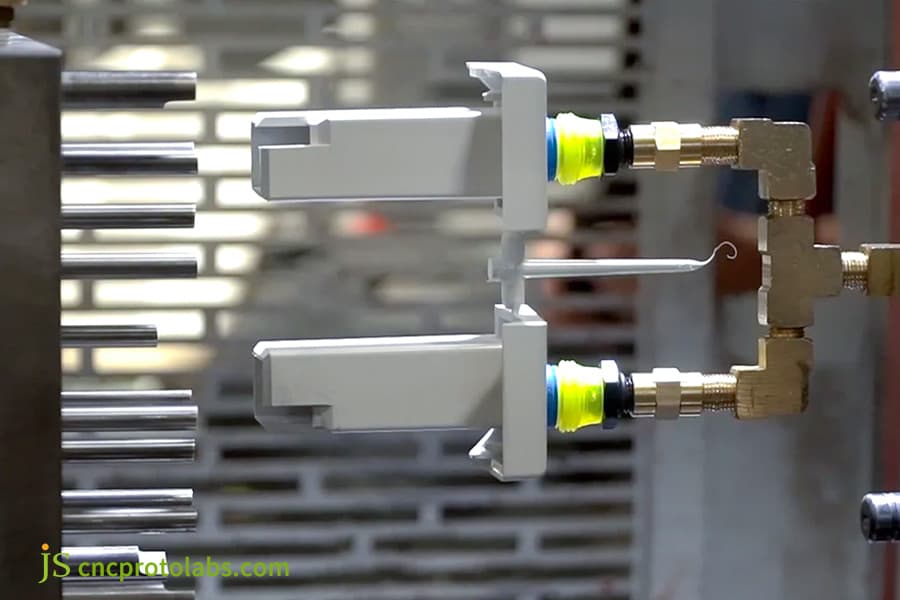
Figure 4: Pneumatic valve manifold with multiple tube connections.
Why Pre-Production Overmold Testing Is Critical For Mass Production Yields?
Single-color injection molding sampling experience is insufficient to address the risk of heat accumulation and cyclic fatigue in multi-material injection molding under large-scale productions. Implementation of strict sampling tests and first-article inspections during small-batch production would fully reveal the effects of batch variations of the rubber compound on the bond strength. The four hardcore validation criteria for pre-production overmold testing are as follows:
Four Quality Control Standards
- Peel Strength Assessment: Based on ASTM D903, carry out a 180° tensile peel test to make sure that the pull-off force or adhesion force exceeds 15 N per inch width.
- High and low temperature thermal shock: Perform 100 cycles of temperature changes from -40℃ to +120℃ to evaluate the CTE shear stress at interface.
- Cross-cut Adhesion Test: Conforming to ISO 2409, cross-cut adhesion should not occur.
- Dynamic Mechanical Analysis: Conduct measurements of storage modulus and the loss factor to evaluate the fatigue life under a long period.
Test Result Comparison Table
| Test Item | Standard Requirements | JS Precision Measured Value | Test Standard | Judgment Basis |
| 180° Peel Strength | > 15 N/inch | 22 N/inch | ASTM D903 | Average Value≥ 15 N/inch |
| Thermal Shock 100 Cycles | No Cracks | Zero Defects | ISO 16750-4 | Visual Inspection + 10x Magnifying Glass |
| Cross-Cut Adhesion | Grade 0 | Grade 0 | ISO 2409 | No Cross-Cut Offset |
| Peel Strength After Thermal Shock | > 12 N/inch | 19 N/inch | ASTM D903 | Attenuation ≤ 20% |
| Dynamic Mechanical Analysis | Storage Modulus≥ 80% | 91% | ISO 6721 | Attenuation after 1000 Cycles |
Pre-production overmold testing is a health check report for mass production yield.
Submit basic project parameters to receive free mold flow analysis and feasibility assessment. A venting scheme and gate optimization report will be provided within 24 hours, avoiding rework during trial molding.
What Are The Standards For Medical Overmolding Components In Our Quality Service?
Medical surgical instruments and parts of endoscopes are repeatedly subjected to high-pressure steam sterilization as well as strong chemical disinfectant environments. Quality control services for medical overmolding components require materials and processes to meet extremely stringent biocompatibility and chemical tolerance boundaries.
Medical-Grade Technical Requirements
Component overmolding quality service for the hardness indicators of medical packaging adhesive:
- Cleanroom Class: Overmolding procedures should be done at the very least in a cleanroom rated as ISO 7.
- Biocompatibility Certification: For the materials being used the certificates to ISO 10993 and USP Class VI are the minimum required ones.
- Interface Roughness: By having a control of the substrate interface roughness at Ra 1.6μm the microscopic concave structure can be used to make up a very strong mechanical anchor that would prevent moisture from getting inside.
Parameters of the Medical Overmolding Process
- Cleanroom Class: ISO 7 which is tested by checking particles level.
- Biocompatibility: To ISO 10993 and USP Class VI standards. A requirement for a third-party to perform and then issue the test reports.
- Interface Roughness: It will be checked that the interface is at a roughness of Ra 1.6μm through the use of a profilometer.
Compliance with the production of medical overmolding components is what it takes to be in the medical supply chain.
Case Study: How JS Precision Solved Delamination for a Medical Endoscope Handle?
Mechanical delamination scrap was a huge issue for a main European distributor of medical equipment at some 18.5% when they mass produced an endoscope handle with a substrate made of PA66+30%GF that was overmolded with a medical-grade TPE shell. JS Precision stepping into the scenario, the scrap rate had dropped almost to 0.2%, from re-designing the interface and controlling the injection molding process.
Customer Difficulties
Linear expansion coefficient difference between the soft and the hard materials resulted in edge curling and peeling during 134℃ moist heat sterilization of the endoscope handle. In addition the surface of the substrate was covered with a layer of loose glass fibers and there was a lot of variation both in roughness and in bond energy.
JS Precision Solution:
- Process Restructuring: The change was the transition from a cold-drawn insert overmolding process to two-color simultaneous two-injection molding. Once the first injection is completed, in about 12 seconds, the robotic arm swings over the second injection cavity, and the surface heat residual left of the 140℃ substrate is exploited to activate molecular chain cross-boundary diffusion.
- Geometry Optimization: A closed, anti-peeling dovetail groove of a depth of 0.6 mm and a width of 1.2 mm was introduced on the parting line.
- Sealing Structure Fine-tuning: To avoid micro level TPE flash from forming on the parting surface of the mold, a steel piece was provided with interference of only 0.04 mm and the clamp force of the 150-ton electric injection molding machine was put to use.
- Mold Flow Parameter Adjustment: There have been applied five-stage progressive filling injected with max shear rate restricted to no more than 32,000 s.
- Change of Material: JS Precision introduced to medical-grade TPE that has been grafted with maleic anhydride through a covalent bonding which is much stronger than the regular physical or chemical bondings.
Lessons Learned
If the substrate contains more than 0.1% moisture in the first injection, microscopic vapor bubbles will form and damage the bonding when heated. A residence time control chain less than 24 hours is necessary during production.
Final Results:
- Peel Strength: The customer's specification is 5.0 N/mm. This has been more than threefold improved to 8.4 N/mm while the initial value was only 2.1 N/mm.
- Production Yield: With an overall increase of 99.8% from the original 81.5%, the production defects declined by more than 99%, reducing the scrap rate by more than 1.8 times per 10.000 units produced.
- Sterilization Test: At the interface, a complete lack of cracks, curling nor discoloring were seen following200 cycles at 134 degrees Celsius high pressure steam sterilization.
- Production Efficiency: The time for dual-shot production cycle was decreased by one second (from 45s to 28 seconds) and as a result the unit cost has decreased by 22%.
- Annual Cost Savings: At a yearly production amount of 500.000 units, direct cost savings in material and manhours are at about $126,000 resulting from the lower reject level.
Customer Feedback
An executive buying manager at the customer said: JS Precision is equipped with more general capabilities of an OEM. The way they support R&D and work together to identify our basic engineering design flaws is quite impressive.
Click now to receive one-on-one engineering diagnostic services from JS Precision experts, replicate their successful zero-dislodgement endoscope handle experience, and secure high mass production yields.
Why Partner With JS Precision For High-Precision Custom Overmolding Service?
High-quality precision overmolded parts cannot be created with great machine tools alone. One also needs the know-how on material compatibility, mold manufacturing accuracy requirements, and how to control injection molding process effectively with the use of real-time feedback. JS Precision will eliminate all the guessing games involved in trial molding through our product development cycles with the assistance of trial molding and product launching will be much shorter. Our custom overmolding service is one of a kind with our ability to hit the target on the first trial as good as 95%.
Hardware Assets and Mold Tolerances
The investment of the company's JS Precision in machine tools largely determines the dimension stability and flash control level of overmolds:
- Two-color Precision Injection Molding Machine Cluster: It has KraussMaffei and FANUC two-color injection molding machines available, from 80-300 tons clamping force, so production is possible at various scales from medical miniature components production to car industry big parts production.
- Mold Machining Tolerances: The workshop-hardened steel molds machining tolerance is stably within 0.005 mm, completely flash preventing during secondary injection molding and the sealing position interference fit is accurate up to 0.03-0.05 mm.
- Advantages of fully electric injection molding machines: Compared to hydraulic presses, the fully electric motor type has a repeatability of ± 0.01 mm and reduces energy consumption by 50%, making it particularly suitable for precision control of medical grade LSR encapsulation.
Technical Service and Quality Certification
As far as JS Precision hardware is concerned, there are more competitive advantages in engineering service and system certification:
- Free DFM & Moldflow Simulation: Covers pre mold opening, the cavity is predicted, the shear rate optimized, the shrinkage compensated through the moldflow simulation. The customer with this method is able to save at least 3-5 potential defects on average.
- 12 Point DFM Checklist: Includes the critical elements of design such as wall thickness ratio, gate position, vent design, and interlocking geometry. Once the design is locked with manufacturing in mind is a real competitive advantage.
- System Certification: Quality management system ISO 9001:2015 and IATF 16949 are both in place and ISO 13485 support for medical projects is also available.
The long-term reliability of custom overmolding service is built on the combination of hardware depth and engineering experience.
FAQs
Q1: What is why determining the cost and overall pricing of a personalized overmolding service project?
The price is mainly affected by: two-color mold opening cost, grade of resin material, number of injection cycles & batch number. A regular wall thickness will reduce cooling cycle, and with a free DFM review this will be the cheapest cost-per-product.
Q2: What are the measures by which Precision JS can assure that delamination will not occur in large numbers during customization plastic-to-rubber injection molding?
By thermal conductivity and solubility parameter matching to get chemical bonding between molecular chains. Through a dual-injection molding machine for fast transfer, the residual substrate heat of around 140℃ starts crosslinking reaction on the interface and the mechanical interlocking completely prevents delamination.
Q3: Why is it suggested that engineers to plan the wall thickness of the substrate during overmolding as a minimum of 1.5mm?
A minimum of 1.5mm of the main part wall thickness can prevent the substrate from erosion of secondary high-pressure melt. Otherwise, when the injection pressure is 120 MPa, and there is heat energy, these conditions can mean melting in a specific area or the substrate getting permanently deformed geometrically.
Q4: For the production of medical overmolding parts, how is bacterial transmission prevented in cases of very strict sterilization requirements?
The use of medical-grade LSR or TPU forms nanoscale molecular unions on the surface of hard plastics, this leaves no space for flash and micropores, and prevents not only body fluids or cleaning water but also bacteria from penetrating the interior during 134℃ sterilization.
Q5: What is the optimal draft angle for mechanical interlocks that help in clean mold release?
To ensure smooth release of the steel part from the mold, the sidewalls having interlocking feature like dovetail grooves or localised recesses must have a 5-7 draft angle so that the removal of the mold is not accompanied by tearing or straining of the edge of elastomer overmolding.
Q6: What could be the rationale for mold cavity pressure monitoring to support overmolding process control soon?
Mold cavity pressure sensors detect changes of melt viscosity and injection quantity immediately so that the system quickly responds by changing the point when holding pressure is switched to a level that prevents the crush of the insert and also removes cross-batch flash and incomplete filling.
Q7: How do different thermal expansion coefficient cause problems in customized overmolded consumer electronics?
A temperature difference will first cause a differential thermal expansion. Materials with mismatched CTE will expand at different rates. Because of this, a huge shear stress builds at their interface, and this will eventually cause the failure in a form of warping, cracking, and delamination of the overmolded layer edges.
Q8: What details are required if one wants to get precision manufacturing quote at an industrial level from JS Precision?
You are required to supply these to receive the quote: With the given details, the engineering team will be able to issue a bespoke commercial quote that does not include any hidden fee in 24 hours. Download a quote and submit your drawings.
Summary
In contemporary multi-component injection molding, preventing overmolding failure demands the combination of mold flow simulation, material compatibility, and the specification of mold dimensions. From DFM wall thickness optimization and dovetail groove keying to mold flow analysis venting and thermal shock testing, every measurable factor is a process barrier which will prevent peeling, melting, and flash.
Now submit your product 3D drawings (STEP/IGES format) and specific chemical resin performance requirements to JS Precision. Our top-level engineering staff will give you a of secondary injection molding feasibility assessment at no charge through 24, with such items as interface polarity matching and gate positioning shear rate simulation, and also a quote plan for the making of precision multi-color molds and mass producing them. Your next level, high-precision multi-component parts will be on a line leading to defect-free mass production even before your first steel mold is chiseled!

Disclaimer
The contents of this page are for informational purposes only. For JS Precision Services, there are no representations or warranties, express or implied, as to the accuracy, completeness, or validity of the information. It is the buyer's responsibility to identify specific technical requirements and request a formal parts quotation. Please contact us for more information.
JS Precision Team
ustom manufacturing solutions. With over 15 years of experience serving more than 1,000 customers, we specialize in high-precision CNC machining, sheet metal fabrication, 3D printing, injection molding, and metal stamping. Having successfully delivered over 300,000 precision parts, we maintain a 99.2% on-time delivery rate across all custom projects.
Our facility is equipped with over 100 state-of-the-art 5-axis machining centers and is ISO 9001:2015 certified. We deliver fast, efficient, and high-quality manufacturing solutions to B2B clients across 150 countries. Whether you require low-volume prototyping or large-scale customization, we support your project with lead times as short as 24 hours. Choose JS Precision for unparalleled efficiency, quality, and professionalism.
To learn more or submit your RFQ, visit our website: www.cncprotolabs.com
Resource

