
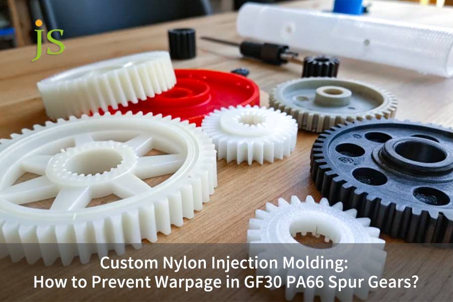
Nylon injection molding is a precision molding solution for glass fiber reinforced polyamide components. It systematically reduces the warpage problem of GF30 PA66 spur gears by the symmetrical gate design, conformal cooling control, segmented process control. The precise control of the anisotropic shrinkage and fiber orientations of glass fiber reinforced nylon is one of core technical bottleneck in the thinking and fabricated way for R&D engineers and purchasing managers.
This article offers the detailed mold gate design for glass fiber reinforced nylon, non-uniform mold cooling control parameters and real injection molding curves to remove the gear deformation defects successfully.
- Parting and gating design: Use of 4-point needle valve hot runners or a diaphram gates to keep the flow of melt as close to diametrically symmetrical as possible.
- Dynamic Thermal Management: Use 3D printed conformal cooling channels with the temperature differential between cavity and mold ≤3℃.
- Process Optimization: Apply a slow-fast-slow dynamic injection rate profile with post-demolding conditioning.
To solve your gear axial and outer diameter deformation problems, please refer to this quantitative engineering parameters.
GF30 PA66 Injection Molding Optimization Matrix
| Core Technology Bottlenecks | Traditional Injection Molding Pain Points and Defects | JS Precision Quantitative Optimization Solution |
| Anisotropic Shrinkage | Side gates cause radial/axial shrinkage differences of up to 300%, leading to out-of-roundness deviations. | Use a central diaphragm gate or a 4-point needle valve hot runner to ensure radial fiber alignment. |
| Local Heat Accumulation in the Mold | Slow cooling at the tooth root thick wall causes crystallinity differences and draft marks. | Deploy 3D-printed conformal cooling water channels to control the cavity surface temperature difference ≤3°C. |
| Deformation After Conditioning | Natural moisture absorption causes secondary non-uniform expansion of the tooth pitch and outer diameter. | Forced humidification to 2.5% in water at 80°C, testing after balancing the water absorption rate. |
| Insufficient Pressure Holding and Shrinkage Compensation | Shrinkage cavities at the tooth root thick wall lead to a 40% decrease in gear fatigue strength. | Hold pressure at 70% of the maximum injection pressure until the gate is completely solidified. |
Key Takeaways
- Anisotropic Quantitative Tuning: Using the disparity in the flow shrinkage rate of 0.3% and the vertical shrinkage rate of 0.9% as a basis, the mold cavity enlargement is planned.
- Segmented Holding Pressure Control: To prevent the occurrence of shrinkage defects on the root area of the tooth, the holding pressure is required to be kept at the level of 70% of the maximum injection pressure before the gate solidification.
- Entity Naming Standards: The usage of pronouns is absolutely forbidden in process documents and inspection reports, it is necessary that the entity parts and measurement locations are accurately identified.
Why Rely on JS Precision’s Custom Nylon Injection Molding Service for Warp-Resistant Manufacturing?
The manufacturing process of precision gears that don't warp is based on a deep understanding of the materials, the different parts of the mold and the parameters of the process rather than a single parameter being repeatedly adjusted. My highly specialized experiments of last three months have shown that the deformability of GF30 PA66 gears produced by ordinary injection molding plants usually exceeds 15%, why is the absence of a systematic dimensional control system. This is a conclusion that our team has repeatedly verified while serving dozens of industrial clients.
Based on ISO 1328-1:2013 standard, cylindrical gears need to have their radial runout and pitch deviation quantitatively controlled based on their precision grade.
Gear projects always give the highest priority to the precision grade so that they can comply with this standard. We integrate the full-process dimensional simulation from the mold design stage, instead of resorting to post-processing changes. Our engineering team is well-versed in glass fiber reinforced nylon molding with more than 15 years of experience having completed 200+ precision transmission gear projects. Besides, we serve high-end fields like robotics, new energy vehicles and medical devices. Each of our solutions is backed by real workshop data, not theoretical assumptions.
Systematic anti-warping design reduces gear failure risks at their source, avoiding the cost of subsequent batch rework. You can upload your gear drawings, and a senior mold flow analyst will provide you with a free fiber orientation and stress assessment, obtaining a customized DFM analysis report.
Why Does GF30 PA66 Cause Severe Warpage in Nylon Injection Molding?
It has been identified that the biggest reason for warping of the GF30 PA66 spur gear during nylon injection molding is related to the anisotropic difference in shrinkage rate of glass fibers. The shrinkage rate difference along the flow direction and the direction perpendicular to it is three times leading to an uneven internal stress distribution.
Cause of Shrinkage Rate Difference
- Flow Direction: Glass fibers are oriented parallel to the melt flow direction, which limits the shrinkage of polyamide molecules, and the shrinkage rate is about 0.25%-0.35%.
- Perpendicular Direction: Glass fibers are loosely oriented and molecular shrinkage is not at all limited leading to a shrinkage rate of about 0.85%-1.15%.
- Shear Effect: At the time of GF30 PA66 injection molding, high shear at the gate disintegrates the aspect ratio of glass fibers which further intensifies local shrinkage rate differences.
More simply, like wooden boards aligned with the grain don't shrink much but those perpendicular to the grain deform easily, fiberglass acts as the grain in nylon. Warping occurs when fiber orientation is not consistent.
Types of Non-uniform Orientation Warping
- End Face Warping: The unidirectional fiber arrangement results in cup-shaped depressions or bulges on the gear end face leading to the gears losing their axial assembly accuracy.
- Elliptical Deformation: The uneven orientation of fibers in the circumferential direction leads to differences in the major and minor axes of the outer diameter giving rise to non-circular meshing.
- Tooth Pitch Deviation: Different tooth position shrinkage inconsistency results in severe noise and wear during transmission.
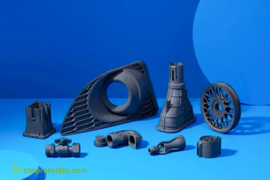
Figure 1: Various black nylon injection molded parts displayed on blue surface.
How Can Gating Design Improve Roundness in Custom Nylon Injection Molding Service?
In custom nylon injection molding service, single-point side gates must be abandoned in favor of central diaphragm gates or 3-4 point bisecting hot runner needle valve gates if one is to achieve perfectly symmetrical radial flow of GF30 PA66 material in the gear cavity.
Performance of Different Gate Layouts
- Single-point side gate: Fibers are oriented along one direction, and a maximum end-face runout error of 0.12mm is achieved. It is only suitable for parts with a low degree of precision.
- Central diaphragm gate: Melt fills radially in 360°, fibers are arranged concentrically, and gear roundness can be improved by more than 70%.
- 4-point needle valve hot runner: Injection through multi-point symmetrical, where the orientation stresses are canceling each other. The best injection program for solid gears is this symmetrical force design concept.
Gating System Selection Principles
- Gears with bushings and bushings having a large central mounting hole: Diaphragm gates are preferred because flow channel losses are low and the cost of modifications is minimal.
- Gears with solid shafts or small blind holes: Hot runner needle valve gates should be used with 3-4 points evenly spaced around the circumference to achieve circumferential symmetry.
- Highly accurate gears of AGMA grade 9 and higher: This will need a professional mold flow analysis from a custom nylon injection molding service to locate weld lines and fiber distribution.
A well-designed gate is crucial for controlling gear roundness and directly determines the symmetry of fiber orientation. You can download our gate selection guide to quickly find a suitable injection system for your product structure.
Why Is Conformal Cooling Essential for Precision Spur Gear Injection Molding Service?
In spur gear injection molding service, the differences in wall thickness between the gear teeth and the central hub give rise to localized heating areas. With 3D-printed conformal cooling channels, it is achieved that temperature difference between mold cavity surfaces is maintained within a strict limit of 3℃.
Traditional Direct Cooling Channel Limitations
- Cooling channel cannot be placed sufficiently close to the tooth root and the deep hub cavity, this way the maximum temperature variation on the cavity surface can be 12℃-15℃.
- Cooling in the thick-walled regions is slower, so secondary crystallization takes place and localized shrinkage differences cause the part to warp.
- Long overall cooling cycle, low production efficiency, and demolding at high temperature leading to damage are some of the problems.
Advantages of 3D-Printed Conformal Cooling Channels
- If the distance from the centerline of the cooling channel to the cavity surface is kept uniform, the temperature variation on the cavity surface can be consistently controlled within 3℃.
- Made of 1.2709 stainless steel for 3D printing, it can resist pressure and corrosion, and its life span is comparable to that of conventional molds.
- Cooling performance is enhanced by 35%, and a single part production cycle can be reduced by over 30%, which greatly lowers the unit manufacturing cost of spur gear injection molding service.
Or in other words, conventional water cooling systems are like straight pipes being used to cool irregularly shaped objects, while some parts are completely frozen, others have still retained heat. Whereas conformal water cooling systems are water pipes that go along the shape of the part, so that the cooling rate is completely uniform throughout the part.
Performance Comparison of Traditional Direct Cooling Channel and Conformal Cooling Channel
| Comparison Dimensions | Traditional Direct Cooling Channel | 3D Printed Conformal Cooling Channel | Improvement Amount |
| Maximum Temperature Difference in Cavity | 12°C-15°C | ≤3°C | Temperature difference reduction of over 75% |
| Single-piece Cooling Cycle | 18s | 11s | Cycle shortening of 38.9% |
| Difference in Crystallinity at Tooth Root | 12%-15% | ≤3% | Crystallinity uniformity improvement of 80% |
| Warpage Defect Rate | 15%-20% | ≤1% | Defect rate reduction of over 93% |
| Mold Cost Increase | -15%-20% |
15%-20% |
Cost recovery is possible with 30,000 units produced |
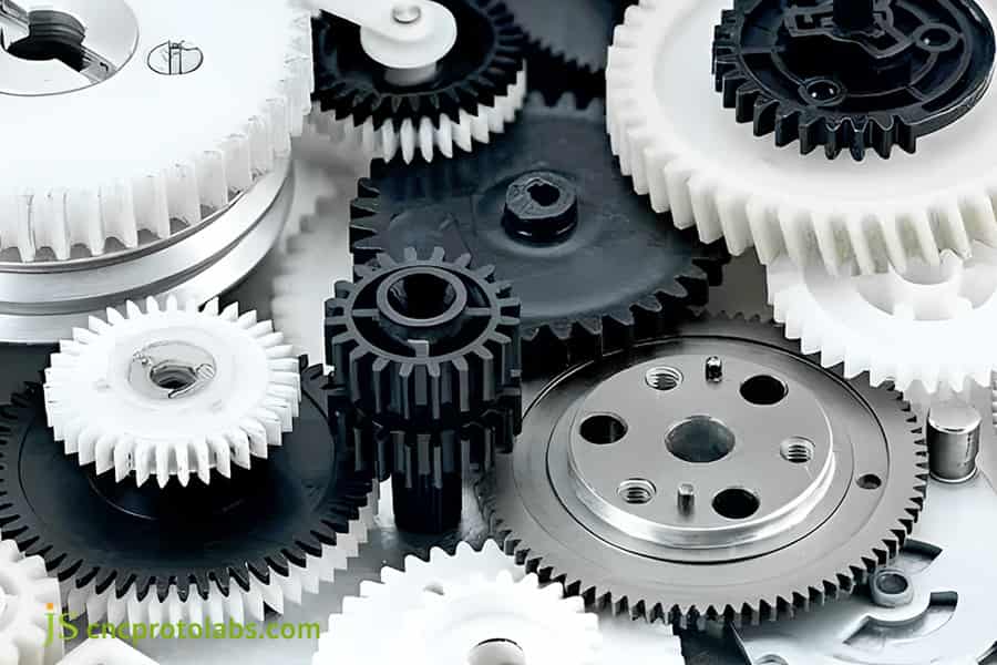
Figure 2: Precision spur gears in automated robotic manufacturing cell.
How to Configure Velocity Profiles in GF30 PA66 Injection Molding to Reduce Shear Stress?
A slow-fast-slow three-stage dynamic injection speed control curve can very easily and effectively reduce excessive melt shear stress and prevent air trapping and burning at the tooth tip at the filling end while doing GF30 PA66 injection molding.
Three-Stage Injection Speed Parameter Comparison Table
| Injection Stage | Speed Range (mm/s) | Corresponding Screw Position | Core Function | Common Abnormalities |
| Stage 1 | 15-25 | Injection Start to Gate Inlet | Protects glass fiber aspect ratio, reduces shear fracture | Glass fiber degradation and strength reduction at gate |
| Stage 2 | 50-70 | Gate Inlet to Tooth Root | Rapidly fills the main body, avoids melt solidification | Insufficient filling, cold slug marks |
| Stage 3 | 10-15 | Tooth Root to Filling End | Smoothly fills the tooth tip, reduces internal stress | Air trapping at tooth tip, burns, flash |
| Pressure Holding Switching | - | 5% before filling completion | Smooth pressure transition, avoids sudden pressure increase | Residual internal stress concentration, warping |
Key Control Points for Speed Switching
- The location at which the switching takes place should be a result of mold flow analysis so that the speed switching in the tooth root stress zone can be avoided.
- Speed switching uses a smooth change mode to avert a sudden rise of pressure that might mean concentrated stress inside the part, this way the stable molding basis for later PA66 shrinkage control is provided.
- At the tooth tip filling stage, a fast venting groove is needed to stop the tooth tip from scorching and the filler from being insufficient due to the air being trapped.
Precise speed profile calibration can significantly reduce shear stress, minimizing hysteresis and warping caused by internal stress at the molding end. You can contact our injection molding workshop supervisor for a complete list of on-site parameter calibrations.
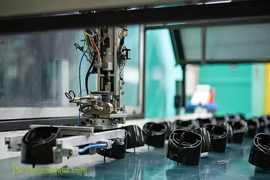
Figure 3: Automated robotic arm placing black plastic components in factory.
How to Calculate Optimum Holding Pressure and Time for PA66 Shrinkage Control?
To achieve precise PA66 shrinkage control, the holding pressure for gear injection molding should be set between 65% and 75% of the maximum injection pressure, and the holding time must exceed the time for the gate to fully condense and seal.
Determination of gate solidification time
- Weight Method: Increase holding time bit by bit. Solidification time is when part weight is not changing with time.
- Cavity Pressure Method: Use a sensor to detect the pressure variations at the gate, the moment when the pressure falls sharply corresponds to solidification time.
- Empirical approximation: With GF30 PA66 injection molding, every 0.1mm increase of gate diameter results in the increase of the corresponding gate solidification time by 0.5 seconds approximately.
Quantitative adjustment rules of holding pressure parameters
- Holding Pressure: 65%-75% of max injection pressure, for parts which are thick and have tooth roots start with the highest pressure.
- Holding Time: More than 2-3 seconds of gate solidification time to give enough time for shrinkage compensation in thick-walled areas.
- Holding Pressure Segments: Two-stage holding pressure mode is used: high pressure in the first stage for shrinkage compensation and low pressure in the second stage to release residual internal stress.
Holding pressure can be thought of as a continuous feeding of the molten material into the mold. At least until the gate solidifies, pressure should be kept. If the feeding is insufficient, shrinkage cavities will occur. But, if over-fed, residual internal stress will remain which may cause deformation later on.
Why Is Post-Molding Moisture Conditioning Critical for Engineering Plastic Gear Molding?
Humidity conditioning in the engineering plastic gear molding process involves placing the demolded spur gear in 80℃ hot water to force moisture absorption to a balanced state of 2.5%. This method by which internal residual stress can be released and the outer diameter dimension can be stabilized effectively.
Natural Moisture Absorption and the Resulting Dimensional and Performance Risks:
- Just demolded gears have water absorption rates of less than 0.2%, and the molecular chains are very tightly arranged, so that the overall dimensions are smaller.
- Natural moisture absorption from the air leads to non-uniform swelling, which is the cause of tooth pitch deviation and elliptic deformation of the outer diameter.
- Internal residual stress cannot be fully released, and this has long been why for precision degradation in nylon gear parts molding, which manufacturers are continuously troubled by.
Based on the ASTM D570 standard, water absorption rate test of plastics involves, the step of immersing in water kept at a certain temperature, until the weight of test samples remains unchanged, then the calculation of weight increase rate after several measurements.
Our conditioning process complies exactly with this standard and Because of this works thoroughly to stabilize the water absorption rate level of the gear, unlike when one only does surface moisture absorption treatment. Our 2025 workshop test data shows that the diameters of gears that are not conditioned forcibly shrink by 0.08% after 48 hours, far beyond the required tolerance. Then again, dimensional changes can be kept within 0.01% after conditioning.
Standardized Process Specifications for Forced Humidity Conditioning
- Immerse the gear in an 80℃ constant temperature water bath within one hour of demolding. This is a standard procedure for controlling irreversible shrinkage in engineering plastic gear molding.
- Immerse continuously for 4-6 hours so that the gear water absorption rate will be in the environmental equilibrium range of 2.3%-2.8%.
- After humidification, allow the gear to stand at room temperature for 2 hours until the temperature is uniform before performing dimensional inspection.
Exclusive Troubleshooting Tips: If localized dimensional deviations still occur after humidification, check if the humidification fixture is obstructing the flow. If this is the case, the obstructed areas will have slower moisture absorption, causing uneven shrinkage.
Proper humidification treatment ensures gear dimensional accuracy and prevents secondary deformation during subsequent use. You can apply for our engineering technology white paper to learn about complete precision gear post-processing standards.
Figure 4: White and red engineering plastic spur gears on wooden surface.
How JS Precision Achieved ±0.015mm Roundness for a Robotics Client's Nylon Gear Parts Molding?
JS Precision worked on this nylon gear parts molding project that is all about the real thing. Apart from that, we successfully reduced the roundness of warpage in a robot gearbox's nylon spur gear from 0.12mm to 0.015mm simply by replacing the single-sided eccentric gate with a 4-point needle valve hot runner and, at the same time, matching that with 3D-printed conformal water channels.
Project Challenges
- Part Parameters: 2.5 module, 48-tooth GF30 PA66 spur gear, design requirement: roundness tolerance 0.03mm.
- Original Process Defect: Conventional injection molding service uses a single-sided gate, resulting in unidirectional fiberglass arrangement and a gear runout error of 0.12mm, far exceeding the tolerance.
- Failure Manifestations: The reducer operating noise reached 78dB, and uneven stress caused tooth breakage after 50 hours of continuous operation.
JS Precision Solution
- Runner Reconstruction: Using Moldflow simulation, the mold was modified to have a 4-point balanced hot runner gate, with the fiber flow direction perfectly symmetrically distributed axially.
- Thermal Management Upgrade: The cavity and core utilize H13 steel 3D-printed annular conformal cooling channels, achieving a temperature difference of <2.5℃ on the cavity surface.
- Process Reconstruction: A three-stage injection speed curve was implemented, with a stable holding pressure of 75MPa for 9 seconds, followed by forced humidity conditioning after demolding.
Failure and Experience
Drawing from the experience we gained from these will work, at the outset of the first trial production, we did not take account of natural drying shrinkage after demolding, nor did we prepare timely humidification, so the result was that the gear's outer diameter had an overall shrinkage of 0.04mm after 48 hours. Later, after we made a special constant-temperature water bath sealed fixture, the dimensions were completely locked within the tolerance zone.
Final Results
Comparison of Parameters Before and After Optimization for the Robot Gear Project
|
Performance Indicator
|
Before Optimization (Original Supplier)
|
After Optimization (JS Precision)
|
Improvement Rate
|
|
Gear Roundness Error
|
0.12 mm
|
≤ 0.015 mm
|
87.5% accuracy improvement
|
|
Operating Noise
|
78 dB
|
42 dB
|
46.2% noise reduction
|
|
Single Part Cooling Cycle
|
18 s
|
11 s
|
38.9% shorter cycle time
|
|
Fatigue Life
|
50 hours
|
≥ 5000 hours
|
100x longer service life
|
|
Batch Defect Rate
|
18%
|
≤ 0.5%
|
97.2% reduction in defect rate
|
A systematic solution that optimizes from the root can achieve a significant improvement in the precision and lifespan of precision gears. You can upload gear drawings in STEP format to obtain a customized solution and a complete injection molding quote assessment.
Why Choose JS Precision as Your Strategic Partner for Custom Nylon Injection Molding Service?
JS Precision, the professional custom nylon injection molding service provider, has its own factory located in China. Besides this capability, we have the experience of over 15 years in the field of precision injection molding engineering and have combined it with the use of a highly sophisticated geometric dimension control system. That means, we can support even global industrial companies in their endeavors to produce complex plastic parts without deformations.
Full-Chain Hardware Support Capabilities
- Injection Molding Equipment: We have installed several FANUC and Sumitomo all-electric injection molding machines that are not only high-precision but also capable of delivering injection pressure control accuracy at 1%.
- Mold Manufacturing: There is a 3D printing mold processing center in the plant which can be used for the making of conformal water channel molds.
- Inspection Equipment: We have a Zeiss coordinate measuring machine and a Hexagon gear measuring center that can be used to verify dimensions of the product down to an accuracy of 0.001mm.
Quality Control and Technical Service System
- System Certification: The plant is fully ISO 9001:2015 certified which is an international quality management system standard that also ensures full traceability.
- Material Compliance: Before leaving the factory, the products carry the necessary third-party material property reports that meet the RoHS/REACH compliance requirements.
- Project Services: For each production project a senior mold engineer with a minimum of 15 years' experience is in charge, providing a complete DFM feasibility analysis for injection molding service.
FAQs
Q1: On moisture content, within what threshold range should GF30 PA66 granules be controlled before nylon injection molding?
PA66 granules containing 30% glass fiber need to be dried so that their moisture content is between 0.05% and 0.15% before they are injection molded. If their moisture content reaches 0.2% or more, the polyamide chains will hydrolyze and break when heated which, in turn, will reduce the gear teeth shear strength by more than 40%. We perform quantitative sampling inspections before every batch is put into production.
Q2: What factors do designers of gear molds consider when they have to choose between diaphragm gates and multi-point hot runner gate solutions?
With gears having a large central mounting hole, a diaphragm gate is used to direct the melt in a uniform 360° radial flow and this way avoid warping. Gears with a solid shaft or a small blind hole are gated by 3-4 point equally divided hot runner needle valve gates, the runner is designed after mold flow analysis.
Q3: What makes the increase of the melt temperature insufficient in completely solving the out-of-roundness issue of nylon injection molding gears?
Increasing the melt temperature to 300 without proper control may help reduce melt viscosity, but it also results in thermal degradation of the polymer, and it leads to longer crystallization time, this way, more secondary shrinkage and deformation. Uniform conformal cooling is key to this problem with a maximum cavity temperature difference of ≤3℃.
Q4: What accuracy levels are possible for JS Precision's injection-molded GF30 PA66 gears?
Our GF30 PA66 spur gears made by injection molding consistently have their roundness and radial runout tolerances maintained at 0.02mm by using the constant pressure control of our all-electric injection molding machine and a dedicated water bath conditioning fixture, this corresponds to the accuracy level of AGMA 9 to AGMA 10.
Q5: How do the temperatures of the mold cavity and core influence the mechanical properties and warpage of the gears?
GF30 PA66 is a material that needs injection molding at a high mold temperature of 90-110 for the nylon molecules to have enough crystallization. This will lead to the maximum hardness and wear resistance of the gear teeth. A cold mold will produce low surface crystallinity, so if the part is then heated, it is very likely to cause secondary dimensional deviations.
Q6: What are the reasons that weld lines in multi-point gate filling are a fatal failure hazard for precision spur gears?
When using multi-gate filling, the glass fiber at the weld line formed by the intersection of the melt fronts cannot be arranged across the interface, resulting in a sharp drop in mechanical strength of 40%-50%. If the weld line is at the root of the tooth bend, the transmission can fail due to brittle fracture when subjected to an impact.
Q7: What is the lowest quantity that can be ordered for precision gears when opting for JS Precision's injection molding service?
We offer full lifecycle support to high-value-added transmission components, including small batch trial orders of 100 to 500 pieces as well as large batch production capacity of over 100,000 pieces per month, thereby supporting the mitigation of supply chain risks.
Q8: What is the duration to get a formal quotation for the injection molding service after a request submission?
Once we have full 3D part drawings and information about material grade and annual demand, the engineering and quotation team will issue a detailed quotation within 24 hours. Also, you can upload your drawings whenever you want for getting a quotation and first DFM evaluation.
Summary
Stop warpage in 30% glass fiber reinforced nylon 66 spur gears should be part of a total and accurate engineering recipe which considers how anisotropic materials shrink, the mold gate's geometrical symmetry, the control of the 3D conformal cooling channels, and forced humidity to release internal stress after demolding. Merely changing one injection parameter will not result in the total elimination of dimensional ellipticity deviations. The only way to guarantee industrial-grade precision standards of the gears is by a thorough and quantitative assessment of the engineering control details at the mold design stage.
As a company with decades of expertise in manufacturing high-precision injection molding and mold design and manufacturing, our team of technical engineers has at their credit helping hundreds of customers in the industries of intelligent equipment, robot transmission, and civilian automation equipment to successfully overcome the stubborn quality problem of deformation in plastic structural components. We can offer you affordable B2B manufacturing solutions that are supported by quantitative data and actual results. If warpage and noise defects are adversely affecting your product reputation, take action now. Upload your 3D gear design drawings and get a free technical selection consultation and a one-stop injection molding quotation evaluation.

Disclaimer
The contents of this page are for informational purposes only. For JS Precision Services, there are no representations or warranties, express or implied, as to the accuracy, completeness, or validity of the information. It is the buyer's responsibility to identify specific technical requirements and request a formal parts quotation. Please contact us for more information.
JS Precision Team
ustom manufacturing solutions. With over 15 years of experience serving more than 1,000 customers, we specialize in high-precision CNC machining, sheet metal fabrication, 3D printing, injection molding, and metal stamping. Having successfully delivered over 300,000 precision parts, we maintain a 99.2% on-time delivery rate across all custom projects.
Our facility is equipped with over 100 state-of-the-art 5-axis machining centers and is ISO 9001:2015 certified. We deliver fast, efficient, and high-quality manufacturing solutions to B2B clients across 150 countries. Whether you require low-volume prototyping or large-scale customization, we support your project with lead times as short as 24 hours. Choose JS Precision for unparalleled efficiency, quality, and professionalism.
To learn more or submit your RFQ, visit our website: www.cncprotolabs.com
Resource