 English



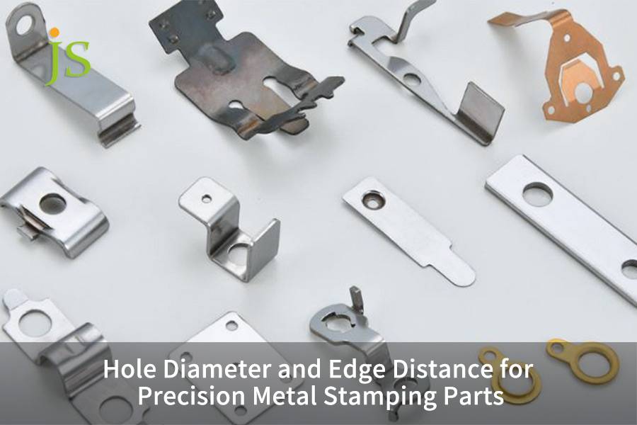

Precision metal stamping hole diameter and edge distance design has a direct impact on the physical strength, shear quality, and die service life of the stamped part. General engineering benchmark requirements: minimum hole diameter is 1.0T–1.2T for low-carbon steel and 1.5T–2.0T for stainless steel and high-tensile alloys. Minimum hole-to-edge distance should be ≥2.0T (≥2.5T+R in bending zones). These limits prevent punch buckling, edge deformation, and tool fracture per VDI 3345 and DIN 9870 standards.
Precision Metal Stamping Design Matrix
|
Material Alloy |
Yield/Tensile (MPa) |
Min Hole Dia. D |
Hole-to-Edge |
Hole-to-Bend |
Die Clearance (%T) |
|---|---|---|---|---|---|
|
SPCC / 1018 Low-Carbon Steel |
240 / 370–440 |
1.0 × T |
1.5 × T |
2.0 × T + R |
8% – 10% T |
|
SUS304 / 316 Stainless Steel |
205–290 / 520–750 |
1.5 × T – 2.0 × T |
2.0 × T – 2.5 × T |
2.5 × T + R |
10% – 14% T |
|
AL 6061-T6 / 5052-H32 Aluminum |
195–275 / 230–310 |
1.2 × T |
1.8 × T |
2.0 × T + R |
6% – 8% T |
|
C2680 / C5191 Brass/Phosphor Bronze |
150–450 / 350–590 |
1.0 × T |
1.5 × T |
2.0 × T + R |
6% – 9% T |
|
High-Strength Steel (SPEN/DP600) |
400–600 / 600–800 |
1.8 × T – 2.2 × T |
2.5 × T |
3.0 × T + R |
12% – 16% T |
Sources: International Organization for Standardization (ISO) — ISO 9013:2017, Thermal Cutting — Classification of Thermal Cuts; JS Precision 2025–2026 project database (1,200+ European projects).
Key Takeaways
- Minimum hole diameter is affected by material hardness: for soft metals, the minimum hole diameter is 1.0T, but for high-tensile stainless steel and alloys, it needs to be at least 1.5T–2.0T to counter shear stress.
- Edge safety distance standard is 2.0T: edge distance being less than 1.5T results in sidewall bulging deformation and burrs caused by plastic flow of the material.
- Rules to avoid bending zones: minimum required clearance is measured from a tangent point where the hole starts to get formed to the edge. To prevent the hole from being stretched off round, the distance L needs to be ≥2.5T + R.
- Micro-hole procedure setup: where D < 1.0T, stepped carbide punch, DLC coating and high-precision guide post stripper plate are essential for dynamic direction and safety.
Why Is Hole Diameter Metal Stamping Limited by Material Thickness?
In punching, the punch is subjected to extreme axial compressive stress. When the hole diameter metal stamping is smaller than the material thickness (D < 1.0T), the reaction force per unit area exceeds the yield limit of tool steel, causing punch buckling failure and shear surface tearing.
Punch force mechanism and Euler bar buckling model
The Euler buckling theory suggests that the punch buckling load critically depends on the fourth power of its diameter. When punch diameter is less than 1.0T, the length-to-diameter ratio is too large, and so a combined effect of lateral friction and punching force will easily lead to instability.
- 0.8 mm SUS304 stainless steel: a lateral friction force of 18% of the punching force is possible with 12% punching clearance, leading to shear-band collapse as well as the burr height more than 10% T.
- 2.0 mm SPCC low carbon sheet: when a blanking gap is 5%, then a bright band of 45%–55% of the section height can be obtained, while the burr height remains in 0.03 mm or below.
Blanking section quality and parameter control
The blanking cross-section can be subdivided into three major zones: the bright band, the fracture area, the surface roughness area or burrs. The extent to which these zones are present has an impact on stamping precision.
- Ratio of the bright band: Ideally, it takes between 40% to 55% of the cross-section height. It results from the plastic shearing when the punch penetrates the material.
- Fracture zone ratio: if the hole punching clearance is too wide, the fracture ratio would be a majority (over 60%) and the material's surface integrity would go down.
- Burr control: A scraping station has to be introduced or the die clearance must be changed if the height of the burrs exceeds 10% T.
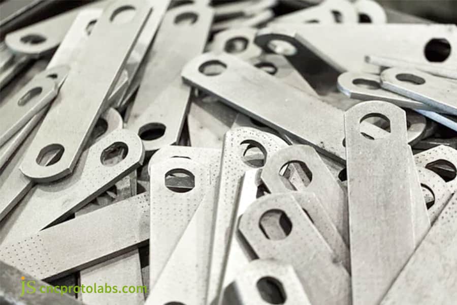
Figure 1: Batch of stamped metal parts with holes.
What Is the Safe Edge Distance Stamping Rule to Prevent Deformation?
The safe edge distance stamping from a hole to the part outer edge is typically 2.0T, and under extreme optimization shall not be less than 1.5T, to prevent lateral extrusion force from breaking through the parent material's plastic deformation zone, causing edge bulging or tearing.
Lateral thrust and edge deformation mechanism in punching
When the material width is very narrow and the edge distance is too short, the die closing pressure will transform into lateral thrust and will lead to the unsupported metal at the edge is pushed apart which results in a straightness deviation above 0.08 mm.
- Edge type difference: The edge distance of sheared edges ought to be ≥2.0T, whereas the edge distance of laser-cut can be relaxed to 1.5T. Then again, bent edges should be ≥2.5T + R.
- The different deformation rates: edge protrusion of the part with the edge distance of 1.0T can reach up to 0.12 mm, whereas for one with edge distance of 2.0T, the value drops under 0.03 mm.
SME Tool and Manufacturing Engineers Handbook specifies a lateral displacement ratio of 0.05 mm/T for punched material thickness. Exceeding that value, an additional post-trimming operation will be necessary.
JS Precision introduces pre-piercing and post-trimming operations in the design of the continuous die stages to ensure the accurate and precision stamping parts will have outer contour accuracy of ±0.015 mm under the narrow edge margin of 1.2T–1.5T.
Edge quality comparison table under different margins
|
Edge Distance |
Bulge Height (mm) |
Straightness Deviation (mm) |
Shear Surface Quality |
|---|---|---|---|
|
< 1.0T |
0.12–0.18 |
0.10–0.15 |
Severe tearing, burr > 15% T |
|
1.5T |
0.06–0.10 |
0.05–0.08 |
Moderate bulge, burr 8%–12% T |
|
2.0T |
0.02–0.04 |
0.02–0.03 |
Clean shear, burr < 5% T |
|
> 2.5T |
< 0.02 |
< 0.02 |
Excellent, burr < 3% T |
Sources: Society of Manufacturing Engineers (SME) — Tool and Manufacturing Engineers Handbook, 9th Edition, 2015; JS Precision 2025 production data validation (8,400+ parts).
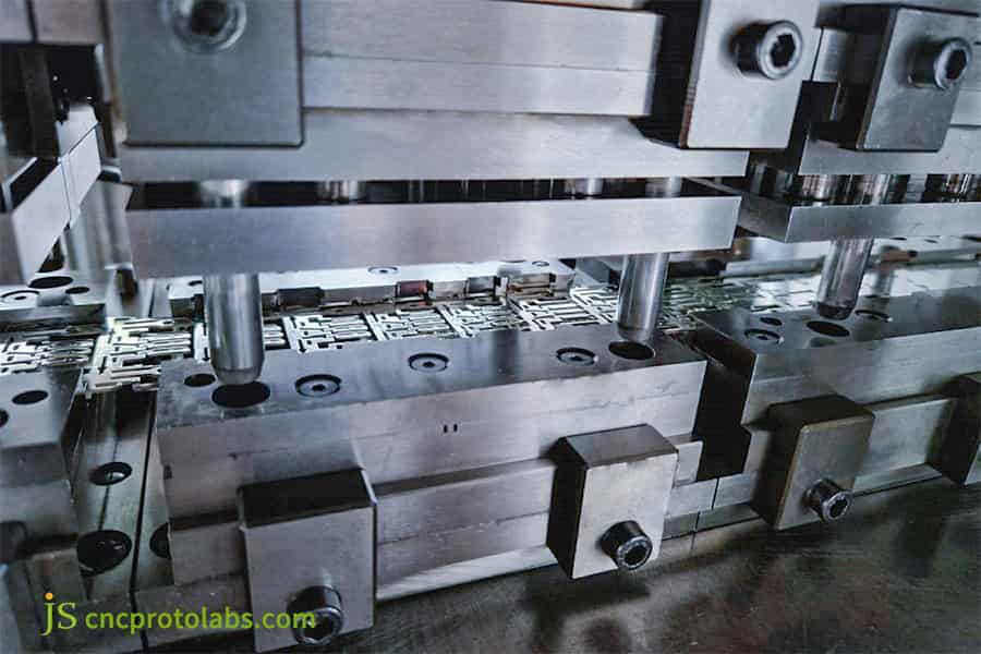
Figure 2: Stamping die tooling for edge distance rule.
How to Calculate Hole-to-Hole Distance in Precision Metal Stamping?
In precision metal stamping, the minimum web thickness between two holes must be maintained at 2.0T to 3.0T or above to counteract grain boundary tearing and local warping caused by cumulative blanking stresses.
Stress interference mechanism of perforated punching
When the wall thickness of adjacent holes is less than 2.0T, the two holes simultaneously being punctured will produce stress fields overlapping each other. As a result, material bridge (Web) will first tear at the grain boundary.
- Case study of the heat dissipation mesh cover: the material bridge breakage rate is as high as 18% when the hole spacing is 1.5T; it decreases to less than 1% after the distance between the holes is increased to 2.5T.
- Step by step punching process: First punch odd holes, then punch even holes, dispersing 40% of the instantaneous punching force.
Progressive Die Layout and Step Size Optimization
The matching of pitch and web width is crucial for dense porous components in sheet metal punching.
- Single-project stamping: punching out all holes at once can be applied where the spacing between holes is the 3.0 times thickness.
- Continuous progressive die: the punching layout is carried out gradually with a step pitch of 2.5 times thickness and a material bridge width of 2 times thickness.
- Nitrogen spring stripper: during high frequency stamping, a clamping force of only 1.5–2.0 MPa is required to the strip so the finished product's flatness is maintained within 0.05 millimeters per 100 millimeters.
Do your porous parts' layout still need optimization to save costs? Get in touch with JS Precision for a free DFM evaluation and help in optimizing your pitch and material bridge design!
How Does Hole-to-Bend Distance Influence Precision Metal Stamping Parts?
The minimum distance from the hole edge to the bend tangent point must satisfy L ≥ 2.5T + R (R is the inside bend radius) to avoid oval deformation of the hole caused by tensile stretching on the outer side of the neutral layer during forming of precision metal stamping parts .
Interference mechanism between bending deformation zone and hole position
When a sheet metal is bent, the internal side gets compressed whereas the external side gets elongated. While punching enters the plastic deformation stage, the circular hole gets elongated, thereby becoming out of shape and resulting in the hole diameter going above the tolerance by 0.05–0.15 mm and reducing the connection joint strength.
- Out-of-roundness measurement: at L = 1.5T + R, the distortion of the hole shape can be 0.12 mm; still, at L = 2.5T + R, it is less than 0.02 mm.
- Influence on fastening power: When the ovality is beyond of 0.08 mm, the tightening force in the bolt connection is decreased by 20%–30%.
Three major DFM solutions
Based on JS Precision's many years of hands-on experience in precision stamping projects, the following three solutions can effectively eliminate the problem of near zone hole deformation during bending:
- Press relief notch: A rectangular groove with a width ≥ 1.0T is made outside the deformation zone during bending to prevent tensile stress propagation.
- In-die oblique wedge piercing: The bending and shaping are finished with a Cam Action Piercing afterwards the hole is punched on the shaped surface with a roundness of ≤0.01 mm.
- Reverse compensation algorithm: during bending stretch, the compensation is calculated beforehand in the CAD stage through an algorithm. The stamp position is then offset by 0.05–0.10 mm in the reverse direction of forming to make up for the hole position change after shaping. This reverse compensation method is the accepted procedure for near-hole design in stamping DFM design guide.
Experiencing near-hole deformation during bending? Get a custom bending compensation solution, we will give exclusive algorithm parameters per your sketches!
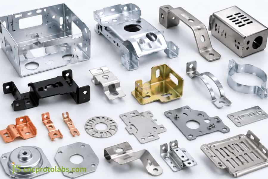
Figure 3: Various metal stamping parts and brackets.
How Can Precision Stamping Tolerances Be Maintained in High-Tensile Alloys?
When blanking work-hardening alloys such as SUS304, SUS316, and high-strength cold-rolled steel, the hole diameter reference must be relaxed to 1.5T–2.0T, or stepped carbide punches with DLC coating must be used to break through conventional precision stamping tolerances limits.
Cold work hardening and punch wear mechanism
Austenitic stainless steel shows a considerable work hardening effect while punching or shearing the material. Punch surface suffers adhesive wear (Galling), which causes the dimension stability of hole diameter fine blanking to reduce.
- SKD11 tool steel: has a hardness of 58–62 HRC, and its single sharpening life is approximately 30,000 punched parts when punching SUS304.
- Ultrafine tungsten carbide punches: punches possess the hardness level HRA 89–92, the resistance strength 4,500 MPa, with a durability life of 150,000 cycles.
- Coating comparison: TiCN coating holds friction coefficient 0.15, AlTiN coating 0.12, and DLC coating has the friction coefficient less than 0.08, which prolongs tool life as much as 300%–500%.
VDI 2906 says that for precision stamping of carbide where the ratio of gap to bright area in cross-section has to be measured, the percentage of bright area should not be less than 50%.
JS Precision uses micro-lubrication (MQL) & shaving processes during high tensile alloy machining to obtain a shear surface roughness Ra 0.4 μm, which meets the precision stamping tolerances in medical and aerospace fields.
Comparison Table of Die Punch Materials and Coating Properties
|
Punch Material / Coating |
Hardness (HRC/HRA) |
Flexural Strength (MPa) |
Friction Coefficient |
Service Life (strokes) |
|---|---|---|---|---|
|
SKD11 (Uncoated) |
HRC 58–62 |
2,500 |
0.25–0.30 |
30,000–50,000 |
|
DC53 (Uncoated) |
HRC 60–63 |
3,000 |
0.22–0.28 |
50,000–80,000 |
|
Tungsten Carbide (WC) |
HRA 89–92 |
4,500 |
0.15–0.20 |
150,000–250,000 |
|
WC + TiCN Coating |
HRA 89–92 |
4,500 |
0.12–0.15 |
300,000–400,000 |
|
WC + DLC Coating |
HRA 89–92 |
4,500 |
0.08–0.10 |
500,000–600,000 |
Sources: Verein Deutscher Ingenieure (VDI) — VDI 3345:2020, Precision Shearing — Fundamentals, Tools, Processes; JS Precision 2025 tooling test report.
Facing challenges with high-tensile alloy stamping? Review our coated punch case studies to understand how different coatings improve die life in practical applications.
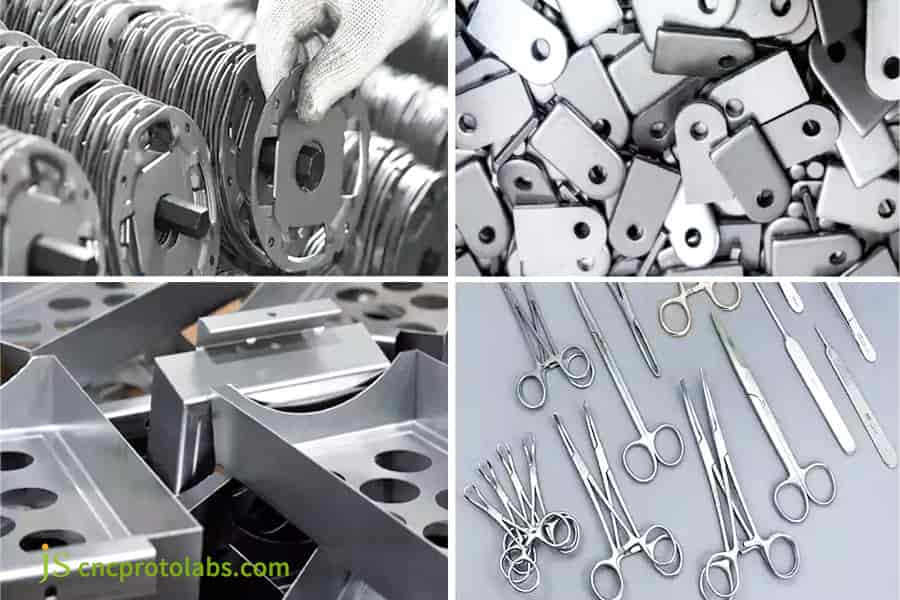
Figure 4: High volume precision stamped parts and tools.
How Does High Volume Metal Stamping Service Optimize Tooling for Slender Punches?
In continuous high volume metal stamping service, the core to ensure slender punch life lies in adopting fully guided stripper bushings and multi-step punch designs to eliminate lateral high-frequency vibration during high-speed stamping.
Fatigue failure modes of slender punches
Under the circumstances of continuous stamping operations producing millions of parts per year, the slender punches would be subjected to alternating stresses of about 200–600 strokes per minute. Thermal fatigue and resonance are the main types of failure caused by this.
- Fully guided stripper bushing reduces punch cantilever length by about 70% and raises the critical buckling load more than 3 times.
- Multistage stepped punch: The punch is composed of a guide section, a transition section and a shearing section for gradually transmitting the load.
- Guide post and guide sleeve fit: 0.002–0.003 mm level fit tolerance and bottom dead center pressure sensor monitoring make it possible to have high volume metal stamping service with low maintenance downtime.
Engineering implementation for mass production
From JS precision automotive connector projects' on-the-job experience, a progressive die that is able to do 5 million pieces each year would need a combination like: 400 operations per minute, one single sharpening life of 500,000 operations, and die maintenance carried out at intervals of 200,000 times. Through the improvement of holes and edges of precision metal stamping parts design, it is possible now to decrease punch fracture down from 2.3% to even less than 0.1%.
Case Study: How JS Precision Solved Micro-Piercing and Edge Distortion for Medical Components?
For a 0.20 mm thick 316L stainless steel micropump diaphragm, JS Precision optimized back-pressure ejection and fine punch guidance to achieve micro-piercing of 0.18 mm diameter holes (D = 0.9T) with 0.25 mm edge distance, maintaining part flatness within 0.02 mm.
Difficulties encountered by customers
A medical device company was tasked with developing a very accurate fluid control valve disc that was made of 316L stainless steel (0.20 mm thickness). The design required 16 closely positioned micro-holes (0.18 mm in diameter, 0.25 mm at the edge) and they were to be punched through the workpiece. Previously, the same supplier provided this type of valve disc with the result that 45% of their products were scrap, the punch broke within 8,000 cycles, and the punched edge was a subject of a 0.04 mm warping deformation that caused fluid assembly seal failure.
JS Precision Solution
- Punch Design and Material Upgrade: A multi-step stepped punch was produced with high-strength tungsten carbide with an ultra-fine grain size of 0.4 microns in the three stages, with the point being coated by TiAlCrN via PVD (physical vapor deposition).
- Clearance and guide optimization: The double-sided cutting clearance was set to 6.5% T (0.013 mm) and zero-clearance ball guide pillars and individual stripper guide sleeves were used.
- Reverse back pressure and scrap control: a 1.5 MPa pneumatic floating block in the lower die suppresses rebound deformation, whereas a micro vacuum scrap suction unit is provided at the end of the punch to prevent the jump of slugs.
JS Precision with its 15 years of expertise in providing custom metal stamping service have successfully raised the lifetime of sharpening of this micro-hole stamping process from the industry standard of 8,000 cycles up to 250,000 cycles.
Lessons learned from failure
In the initial trial molding process, the high viscosity of conventional stamping oil caused slug obstruction and small fractures in the punch. By changing over to a highly volatile micro-lubrication (MQL) system, the engineers managed to totally eliminate the slug blockage issue.
Final result
- Die life: 250,000 strokes between each sharpening.
- Micro-hole precision: Roundness is controlled together with hole diameter tolerance at a constant ±0.005 mm deviation.
- Flatness regulation: final flatness of the item is kept to be a maximum of 0.015 mm deviation.
- Ratio of success: The yield rate of large-scale production has been 99.4%.
Sources: Deutsches Institut für Normung (DIN) — DIN 9870:2019, Stamping Tools — Tolerance and Life Assessment; JS Precision internal test report TR-2025-MED04.
Need to optimize the bore tolerances of your stamped parts or solve the problem of deformation in narrow margins? Send your 3D CAD model and 2D engineering drawings to JS Precision now, and our engineers will provide a DFM assessment and quotation within 12 hours.
FAQs
Q1: Can the hole diameter in precision metal stamping be smaller than the material thickness?
Yes. With 0.1–0.5 mm thin stainless steel or copper sheets, JS Precision uses ultra-fine particle hard alloy stepped punches and fully guided stripper sleeves. This allows them to achieve micro hole punching with hole diameter equal to 0.8 times material thickness, and the tolerances are controlled at ±0.008 mm.
Q2: What happens if the stamping edge distance is less than 1.5T?
If punching edge distance is shorter than 1.5T, the lateral thrust from punching causes the outer edge to widen due to lack of support from the base material, creating protrusions in the outline and deviation in straightness beyond 0.08 mm. So, a secondary cutting or pre-trimming needs to be incorporated on the die.
Q3: What is the difference between stamped holes and laser-cut holes in edge distance?
Laser cutting is a non-die, thermal material processing technique that offers great flexibility. It is feasible to make laser cut holes with sizes up to diameter of 0.5T and edge distance reduced to 1.0T. But, the drawback is the taper problem and the HAZ (Heat Affected Zone). In case of mass production, stamping has a lower per-unit cost and cycle time compared to laser cutting.
Q4: Why do holes near a bend line deform into an oval shape?
Material surrounding the bending area suffers uniaxial tensile strain. The tensile forces tear hole surroundings if their distance from hole edges is less than 2.0T + R, resulting in out-of-roundness. This deformation can be prevented either by creating a pressure-relief or via the in-die post-punching.
Q5: How can tool designers prevent cracking between closely spaced holes?
In such a case where the wall thickness of an adjacent hole is less than 2.0 mm, holes are alternately stepped and punched by a progressive punching design. A nitrogen spring stripper plate applies high clamping pressure to release the material from the hole wall. The method prevents stress superposition and cracking of material during punching.
Q6: What precision tolerances can be achieved for stamped hole diameters?
Typically, the progressive die hole punch hole diameter tolerance is from ±0.02 mm to ±0.05 mm. In case of a stripping/scraping station or fine blanking process, JS Precision can maintain the hole diameter tolerance and hole location within ± 0.005 mm to ±0.010 mm stably.
Q7: How can engineers get an accurate DFM review and quote from JS Precision?
Through the company website customers send 3D CAD files (STEP/IGES), and 2D engineering drawings indicating tolerance. JS Precision will complete the DFM evaluation within 12 hours and provide an optimized punching spacing plan and a tiered production quotation.
Q8: What factors most significantly affect the piece price in high-volume metal stamping?
The main cost drivers are material utilization rate, the number of die stations, strokes per minute (SPM) and cycle time and punch wear. Properly designed DFM helps avoid punch wear and reduce time spent regrinding, cutting overall production costs up by 15% to 30%.
Summary
Punch diameter and edge distance design are key in controlling tolerances and tool life. For example, adhering to D ≥ 1.0T–1.2T (low carbon steel), D ≥ 1.5T–2.0T (high strength alloy steel), hole edge distance ≥ 2.0T, and L ≥ 2.5T + R allows for elimination of punch breakage & edge deformation and ensures achieving high yield mass production.
If you are working on optimizing the hole diameter tolerances of precision stamped metal parts and facing difficulties with deformation in narrow margins, JS Precision offers comprehensive DFM support for precision stamping projects. Just send us your part drawings, and our experts will promptly provide you with a free DFM analysis and a quote for mass production.

Disclaimer
The contents of this page are for informational purposes only. For JS Precision Services, there are no representations or warranties, express or implied, as to the accuracy, completeness, or validity of the information. It is the buyer's responsibility to identify specific technical requirements and request a formal parts quotation. Please contact us for more information.
Resource

