 English



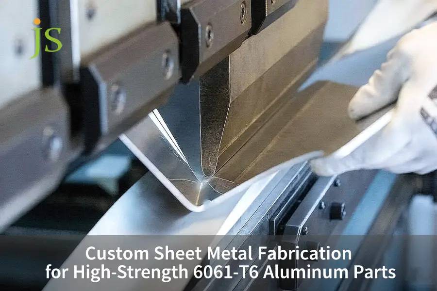

Custom sheet metal fabricating for high-strength aluminium parts means cutting, forming and assembling heat-treatable alloys such as 6061-T6 without triggering bend fracture or dimensional failure. The difficulty is specific and measurable: artificial aging drops elongation from about 22% in the O temper to 8–10% in T6, springback rises from 1.5–2.5° (5052-H32) to 5.0–8.0°, and the safe inside bend radius grows from 1.0t to 3.5t–4.5t. Get any one of those wrong and a battery enclosure, automation frame or robot bracket cracks at the bend.
6061-T6 vs 5052-H32 Bending Parameters for Custom Sheet Metal Fabricating
|
Core Consideration Parameter |
General Bending Aluminum (5052-H32) |
Structural High-Strength Aluminum (6061-T6) |
Workshop Execution Plan & Engineer Design Avoidance Suggestions |
|---|---|---|---|
|
Yield & Tensile Strength |
Yield 195 MPa / Tensile 230 MPa |
Yield 276 MPa / Tensile 310 MPa |
6061 load capacity increases by ~40%, but plastic reserve is extremely low |
|
Recommended Min Inside Bend Radius (R/t) |
1.0t (easy small-radius bending) |
3.5t to 4.5t (prone to brittle fracture) |
For 2.0mm thickness, inside radius must be ≥ R7.0mm; sharp corners strictly prohibited in 3D drawings |
|
Bend Angle Springback Range |
1.5°–2.5° (small linear springback) |
5.0°–8.0° (large non-linear springback) |
Requires CNC servo press with dynamic angle sensor closed-loop compensation |
|
CAD Unfold K-Factor Recommendation |
0.38–0.42 (conventional calculation) |
0.44–0.48 (outer fiber tension in large radius) |
Must verify bend deduction with manufacturer in advance to avoid short blank length |
|
Hole-to-Bend Line Safety Distance |
≥ 2.5t + R |
≥ 4.0t + R (affected by large V-opening) |
If spacing too small, must bend first then mill hole, or cut stress relief groove on bend line |
Across 1,200+ European projects in our 2025 database, 6061-T6 cut with high-purity nitrogen showed no dross and flatness within 0.1 mm.
Four things prevent 6061-T6 bend cracks at once: generous inside radii, bend lines running across the rolling direction, a wide V-die, and a dross-free nitrogen-cut edge.
Why Does 6061-T6 Aluminum Sheet Metal Crack During Bending?
In custom sheet metal fabricating, 6061-T6 aluminium cracks during bending because artificial aging locks the precipitation-hardened Mg₂Si structure in place,dropping elongation from about 22% to 8–10%. Once outer-fibre tensile strain exceeds what the aged microstructure can take, cracks initiate at the grain boundaries.
Artificial aging and elongation decay mechanism
- In 6061-T6, artificial aging precipitates a fine Mg₂Si dispersion that raises strength and drops elongation to 8–10%.
- Cleavage type fracture starts along the boundary of a grain only after tensile stress at the surface reaches the yield stage.
- A larger die radius, combined with a bend line running across the rolling direction, is what removes cracking in practice.
Anisotropy of rolling and bending direction
- Cracking is most likely when the bend line runs parallel to the rolling direction.
- Orient the bend line at 90° to the rolling direction. Bending across the grain allows a tighter radius before cracking starts.
- JS Precision nests every blank so that bend lines run across — that is, at 90° to — the rolling direction.
|
Aluminum Temper State |
Tensile Strength (MPa) |
Elongation (%) |
Min Bend Radius (R/t) |
Crack Risk in Cold Bending |
Recommended Application |
|---|---|---|---|---|---|
|
6061-O (Annealed) |
150 |
20–25 |
1.0t |
Minimal (<1%) |
Complex contours, tight radii |
|
6061-T4 |
240 |
15–18 |
2.0t |
Low (5–10%) |
Moderate forming |
|
6061-T6 |
310 |
8–10 |
3.5–5.0t |
High at R ≤ 1.0t — up to 45% of parts crack. <2% at R ≥ 3.5t. |
Structural, high-load |
ASTM B209 specifies the mechanical property limits for 6061 sheet and plate — 6061-T6 must reach 276 MPa yield and 310 MPa tensile at 0.6–6.0 mm thickness.
Not sure whether your radius will crack? Send the STEP file and we will tell you the minimum safe radius for your alloy and thickness — free, no quote required.
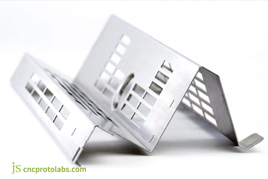
Figure 1: Bent aluminum sheet metal brackets with slots.
How to Calculate Safe Bend Radii and Flat Patterns for High-Strength Aluminum?
Calculating safe bend radii for high-strength aluminum sheet metal fabrication requires setting the inside bend radius between 3.5t and 5.0t, paired with an adjusted K-factor of 0.45 in sheet metal CAD settings. Standardizing these values ensures tensile fiber strains remain under 10%, preventing visible micro-fractures while guaranteeing that flattened cut lengths precisely match folded dimensions after mechanical springback recovery.
Minimum inner bend radius calculation and tolerance compensation
- The safe inner bending radius is 3.5 to 4.5 times sheet thickness — so R7.0 to R9.0 mm on 2.0 mm sheet.
- A sharp corner (R ≤ 1.0t) means forming in annealed 6061-O and then re-solution-treating and ageing back to T6.
- The custom sheet metal fabrication workshop prioritizes reviewing whether the inner bending radius meets the specifications when receiving drawings.
K-factor adjustment rule and neutral layer shift
- Set the K-factor in your 3D CAD sheet metal settings to 0.44–0.48 for 6061-T6.
- Large bend radii push the neutral layer outward, so if you unfold with the conventional 0.38, the blank comes out 1.0–2.0 mm short.
- Confirm bend deduction with your fabrication partner before release — an undersized blank is the single most common cause of assembly failure on folded aluminium parts.
V-die opening selection and surface protection
- Pair a generous punch nose radius with a wider lower die: open the V from the 6t used for mild steel to 8t–12t.
- Decreasing shear stress per unit length is effective in the prevention of surface scratches and microcracks.
- As for JS Precision high-strength aluminum sheet metal fabrication line of products, we standardise on 10t–12t V-die openings.
|
Material Thickness (mm) |
Inside Bend Radius (3.5t–4.5t) |
Recommended V-Die Opening (8t–12t) |
CAD Unfold K-Factor (0.44–0.48) |
Bend Deduction Reference (mm) |
|---|---|---|---|---|
|
1.5 |
R5.25–R6.75 |
12–18 mm |
0.44–0.46 |
2.40–2.60 |
|
2.0 |
R7.00–R9.00 |
16–24 mm |
0.45–0.47 |
3.20–3.50 |
|
3.0 |
R10.50–R13.50 |
24–36 mm |
0.46–0.48 |
4.80–5.20 |
|
4.0 |
R14.00–R18.00 |
32–48 mm |
0.47–0.48 |
6.40–6.80 |
ASTM B209-14 Standard Specification for Aluminum and Aluminum-Alloy Sheet and Plate specifies mechanical properties and dimensional tolerances for 6061-T6 sheet up to 6.0mm thickness.
Bend deduction per 90° bend, calculated as BD = 2(R + t) − (π/2)(R + K·t). Verify against your own press brake tooling before release.
Unfolding in SolidWorks or Inventor? Ask for our 6061-T6 K-factor and bend deduction table — it ships free with every quote.
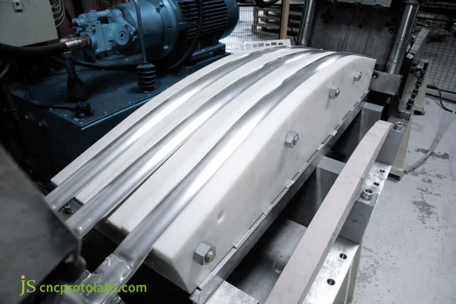
Figure 2: Machine bending high-strength aluminum sheet metal.
How to Eliminate Springback in Aluminum Sheet Metal Bending Operations?
Eliminating springback in aluminum sheet metal requires dynamic angular overbending, wider V-die geometries, and CNC servo presses with real-time laser angle measurement. High-strength aluminium springs back by up to 8° on a nominal 90° bend, meaning fabricators must compress the flange to 82°–84° using closed-loop pressure corrections to hit target geometry upon stroke release.
Comparison of elastic recovery mechanism and modulus
- 6061-T6 has an elastic modulus of about 70 GPa and springs back 5.0°–8.0° on unloading.
- Microstructural variation between batches adds ±1.5° of scatter, which fixed tooling cannot absorb.
- High-End sheet metal forming operations need to make use of on the fly angle measuring devices for error cancellation.
Dynamic over-bend compensation and laser angle measurement
- The CNC servo bending machine with dual laser angle sensors scans the angle continuously and overbends the flange to 82°–84° automatically.
- The CNC system dynamically corrects the compression depth based on the measured springback amount, thus achieving closed-loop control.
- JS Precision's precision sheet metal fabrication services lock angular tolerances within ±0.3°.
Bottom-dead-centre dwell and micro-creep control
- A 78°–80° die with a 1.5–2.0 s dwell at bottom dead centre lets the lattice creep microscopically, which locks in the angle.
- Keeping the pressure also helps in distributing the internal stress in the material evenly, and reduces elastic recovery on release.
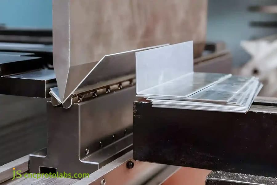
Figure 3: Press brake bending aluminum sheet metal part.
Should You Bend Pre-Hardened Aluminum or Anneal Before Heat Treatment?
Choosing between pre-hardened forming and post-forming heat treatment for custom aluminum sheet metal parts depends directly on component geometry, flange compactness, and tolerance allowances. Forming directly in the 6061-T6 temper avoids distortion but requires large bend radii, whereas complex deep contours or tight radii demand forming in the ductile O-temper, followed by solution quenching and artificial aging back to T6 specification.
Pre-hardened plate cold bending route and tolerance risks
- Buying 6061-T6 sheet in the delivered temper avoids heat treatment entirely, but the inside radius must be at least 3.5t.
- If a large radius is acceptable, this is both the fastest and the cheapest route.
Annealed forming and solution aging recovery
- If the design only has room for a 1.5t radius, then for stamping and forming the 6061-O annealed sheet (elongation ≥ 20%) is recommended.
- The part then goes into a vacuum furnace for solution treatment at 530 °C, followed by artificial aging at 175 °C for 8 h, which restores the T6 temper.
- Quenching can warp the part, so a dedicated hydraulic conforming fixture is used during heat straightening to remove the distortion.
Cost, delivery time, and modification decision-making logic
- The pre-hardened route avoids heat treatment cost but carries a higher material price per part.
- Route B adds 25–45% to processing cost but allows a much more compact design.
- On a 2025 inspection robot chassis project, the pre-hardened route cut unit cost by 34% and removed 9 days from the schedule. Choosing between the two routes means weighing material price against heat treatment cost and design freedom.
ASTM B918/B918M Standard Practice for Heat Treatment of Wrought Aluminum Alloys specifies solution quenching at 530°C and artificial aging at 175°C for 6061-T6 temper restoration.
Facing a dilemma in choosing a high-strength aluminum bending process? Send your STEP drawings to JS Precision now to receive a free DFM review report from senior engineers.
How to Prevent Micro-Cracks and Dross in High-Precision Laser Cutting?
Preventing micro-cracks and dross in aluminum laser cutting relies on high-power fiber lasers assisted by ultra-pure nitrogen at 1.6–2.0 MPa. The nitrogen jet expels molten material before it can oxidise, leaving an edge with no brittle oxide notch to start a crack during forming that withstand subsequent heavy-duty forming stresses without generating fracture initiation notches.
The Influence of Nitrogen Purity and Pressure on Edge Cutting Quality
- Use nitrogen assist gas at 99.999% purity or better, delivered at 1.6–2.0 MPa at the nozzle.
- The high-velocity jet clears the molten material and leaves a surface almost free of oxide or discoloration and has a roughness Ra ≤ 3.2μm.
- In our own runs, nitrogen purity is directly proportional to bend-crack resistance: every drop in purity shows up as more edge cracking on the brake.
Oxidized slag layer and stress concentration fracture source
- Compressed-air cutting leaves a hard, brittle aluminium oxide layer with a micro-serrated profile that adheres to the cut edge.
- Bending concentrates stress at each serration notch, and those notches grow into visible cracks.
- JS Precision entirely stops compressed air cutting of high-strength aluminum, which means only high-purity nitrogen can be used.
|
Assist Gas Type |
Purity / Pressure |
Edge Roughness (Ra) |
Dross Formation |
Bending Crack Risk |
Workshop Recommendation |
|---|---|---|---|---|---|
|
Compressed Air |
Oil-water sep. / 0.8–1.2 MPa |
Ra 6.3–12.5μm |
Heavy Al2O3 slag |
High (stress concentration) |
Strictly prohibited for 6061-T6 |
|
Oxygen (O2) |
99.5% / 0.5–0.8 MPa |
Ra 3.2–6.3μm |
Oxidized burrs |
Very High (embrittlement) |
Not applicable for structural aluminum |
|
Ultra-Pure Nitrogen |
≥99.999% / 1.6–2.0 MPa |
Ra ≤3.2μm |
Zero dross |
Minimal (smooth edge) |
Mandatory for high-strength aluminum sheet metal fabrication |
Across more than 3,000 laser-cut 6061-T6 parts in 2025, nitrogen at 1.8 MPa held edge roughness to Ra ≤ 3.2 μm with no dross.
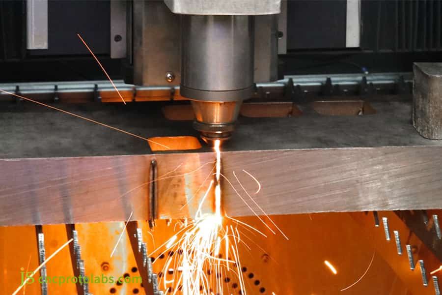
Figure 4: Laser cutting aluminum sheet metal with sparks.
Why Mechanical Fastening and Clinching Replace Welding in Structural Aluminum?
Mechanical fastening and self-clinching hardware (PEM-type) replace fusion welding in structural aluminum because heat input permanently destroys artificial precipitation tempers, reducing heat-affected zone strength by up to 40%. Riveting, cold clinching, and self-clinching studs deliver repeatable structural joints without introducing thermal warping, weld porosity, or the need for expensive post-weld solution re-aging treatments.
Analysis of Strength Degradation and Deformation in Heat-Affected Zone
- In the heat-affected zone, the welding arc coarsens or dissolves the Mg₂Si precipitates that give 6061-T6 its strength, so the HAZ softens to 60–70% of base metal strength — a 30–40% loss.
- Thin plate also warps and buckles after welding, and will not sit flat.
- To prevent heat deformation, so structural aluminium assemblies increasingly use cold mechanical joining instead.
Selection of Press-fit Fasteners and Chamfering Rules for Bottom Holes
- Self-clinching nuts are high-hardness stainless steel and must be installed on a CNC press, not by hand.
- Chamfer the hole 0.2 mm × 45° before installation.
- JS Precision conducts a 100% chamfer check during the riveting process to stop the occurrence of installation cracks.
Synergistic process of self-piercing riveting and structural adhesive
- Box structures are joined with self-piercing rivets (SPR) combined with a high-modulus structural adhesive — a hybrid known as riv-bonding.
- The hybrid joint carries shear and peel loads well and introduces no thermal distortion.
Replacing a welded aluminium assembly? Send the STEP file and we will quote an SPR plus structural adhesive alternative, with joint strength data.
How Do Anodizing and Chemical Passivation Impact Tight Mechanical Tolerances?
Controlling finishing tolerances in precision aluminum parts requires calculating exact anodic film build-up ratios and reserving clearance on critical features before finishing. Hardcoat anodizing creates a 25–50μm oxide layer that penetrates 50% into the substrate and builds 50% outward, requiring machinists to mask tight dowel holes and tap threads to preserve engineering assembly fits.
Trivalent chromium conversion coating and conductive passivation specifications
- A trivalent chromium conversion coating is under 1.0 μm thick and meets RoHS and MIL-DTL-5541F (Class 1A or Class 3).
- It withstands 168–336 hours of neutral salt spray per ASTM B117, and is thin enough to leave hole and thread tolerances unchanged.
- Precision sheet metal fabricators are the primary users of this finishing method for tight-tolerance assemblies.
Hard anodized film growth and subtraction logic
Hardcoat anodizing to MIL-PRF-8625 Type III builds a 25–50 μm oxide layer. Critically, the coating grows roughly half inward and half outward. On a 25–50 μm hardcoat that means each external surface grows by 12–25 μm, and a hole diameter shrinks by 25–50 μm.
Compensation therefore has to be built in before anodizing — at the blanking or machining stage — on small threaded holes and precision locating holes.
Practical application of shielding and tolerance compensation
- Acid-resistant rubber plugs mask the holes in the anodizing bath and protection to prevent any variation in the hole size inside.
- Precision locating holes are rough-bored undersize before anodizing, then re-bored to final size afterwards.
- Based on JS Precision's practical experience in medical aluminum component projects in 2025, shielding protection stabilizes the fit tolerance at ±0.05mm.
JS Precision Case Study: Manufacturing 6061-T6 Chassis for Industrial Inspection Robots
JS Precision delivered a high-strength chassis fabrication solution for an industrial inspection robotics client, achieving ±0.1mm dimensional alignment across 16 folded facets in 2.5mm 6061-T6 aluminum. By replacing risky fusion welding with structural PEM fasteners, applying a 4.0t inside bend radius, and tuning CNC overbending parameters, the team eliminated previous 45% scrap rates caused by brittle edge cracking.
The customer's problem
- The previous supplier used conventional press brake tooling and compressed-air laser cutting. The cracking rate on bent parts reached 45%, and accumulated springback across the 16 facets ran to 4.5° per bend.
- The motor mounting holes were not coaxial, which halted trial production and put the customer's line schedule at risk.
- The whole process chain needed a full DFM rework, urgently.
JS Precision Solution
- Our DFM review replaced the original R2.0 mm corner with R10.0 mm (R/t = 4.0) and added stress-relief grooves at holes near the bend line, and also pre-cut the stress relief grooves along the bending line for the irregularity-affected holes.
- All bend lines were nested across the rolling direction. Blanks were cut on a 10 kW fiber laser with 1.8 MPa high-purity nitrogen assist.
- We overbent to 83.2° and held pressure at bottom dead centre for 2 s to absorb the measured 6.8° of springback. Welding was replaced entirely with stainless steel self-clinching studs for fastening, and the surface was passivated by using trivalent chromium.
Failure experience and lessons learned
The microcrack originated during the trial run when an operator transferred the unfinished prototype part to the bending machine before completing the deburring stage. A 0.8 mm crack was found originating at the laser pierce start point. We made it a mandatory step: every high-strength aluminium blank is edge-broken (micro-blunted) on an eccentric roller sander before it goes to the brake.
The technical department then implemented a mandatory process: following the laser cutting of high-strength aluminum parts, their edges are to be entirely deburred with a micro-blunting method done using an eccentric roller grinding machine before they can be moved to the bending stage.
Final result
- All 150 chassis shipped crack-free, with the main mating holes within ±0.08 mm. The chassis passed a 500 kg static load test and 100 hours of vibration durability testing.
- Against the previous welded steel design, the new chassis weighed 35% less and final assembly time dropped from 4 hours to 45 minutes.
- Unit cost fell 34% and the delivery schedule shortened by 9 days.
Data source: JS Precision Internal Engineering Report Project QA Report: Industrial Inspection Robot Chassis Batch #2025-ROBOT-08.
Upload your 3D CAD (.STEP/.IGES) and 2D drawing with tolerances and finish. A senior engineer returns a DFM review and itemised quote within 12 hours.
FAQs
Q1: Why does 6061-T6 aluminum crack easily during cold bending?
After artificial aging, 6061-T6 only shows an elongation of around 8–10% and a very low plasticity. The moment the outer edge is under tensile strain that is higher than the fracture toughness of the brittle grains, intergranular cracks will form.
Q2: What is the recommended minimum bend radius for 6061-T6 sheet metal?
The minimum bend radius for 6061-T6 should be at least 3.5 times the sheet thickness which means 7 mm for R2 mm plates. Yet, if the desired shape includes a sharp corner (R ≤ 1.0t), the workpiece must be stamped with 6061-O material followed by the necessary reheat treatment in the form of quenching and aging.
Q3: How does springback vary between 5052-H32 and 6061-T6 during press braking?
5052-H32 springs back 1.5°–2.5°; 6061-T6 springs back 5.0°–8.0° because of its higher yield strength. Controlling it requires either dynamic compensation on a CNC servo press brake or in-line laser angle measurement.
Q4: Can structural 6061-T6 enclosures be assembled using traditional TIG welding?
Welding should be avoided for load-bearing structural components. The high temperature of welding causes a 30%–40% loss in the strength of the heat-affected zone and makes it prone to warping; self-piercing riveting (SPR) and press-fit fasteners combined with structural adhesives and other cold connection processes are recommended.
Q5: What CAD K-factor should be configured for high-strength aluminum unfolding?
Set it to 0.44–0.48 instead of the 0.38–0.42 used for 5052. Large-radius bends shift the neutral layer outward, and the lower value produces undersized blanks and out-of-tolerance forming.
Q6: How much does custom 6061-T6 sheet metal fabrication cost compared to mild steel?
Typically 20–40% more. The drivers are higher material price, slightly lower nesting efficiency, the cost of high-purity nitrogen assist gas, and longer cycle time on the brake for set-up and angle correction.
Q7: What documentation does JS Precision require to generate a formal quote?
The client should send a complete 3D CAD model (STEP/IGES) and 2D engineering drawings (PDF) with key tolerance, crimped parts models, and surface treatment standards indicated. JS Precision will deliver a free DFM and an itemized quotation within 12 hours.
Q8: How does JS Precision ensure consistent angular accuracy across volume production?
JS Precision runs CNC press brakes with in-line laser angle measurement that reads springback in milliseconds and corrects in closed loop. Combined with incoming hardness sampling and first-piece CMM inspection, that holds batch angle tolerance to ±0.3°.
Summary
Precision machining of high-strength 6061-T6 aluminum sheet metal requires a holistic approach, integrating design and workshop processes: internal bending radius ≥ 3.5t, bending lines perpendicular to rolling texture, high-purity nitrogen cold cutting to eliminate micro-cracks, and dynamic compensation for 5.0°–8.0° springback. Small-radius stamping and welding are abandoned in favor of cold assembly processes to ensure reliable part placement.
If your equipment rack is facing bending, cracking, or angular deviations, please contact the JS Precision engineering team. Upload your 3D CAD drawings (.STEP/.IGES), and a senior engineer will provide a DFM analysis and tiered quote within 12 hours, ensuring reliable quality for mass production.

Disclaimer
The contents of this page are for informational purposes only. For JS Precision Services, there are no representations or warranties, express or implied, as to the accuracy, completeness, or validity of the information. It is the buyer's responsibility to identify specific technical requirements and request a formal parts quotation. Please contact us for more information.
Resource

