

Gear manufacturing serves as the fundamental element which guarantees the operational stability of wind power systems. A 5MW offshore wind turbine experiences more than ten thousand dollars in daily operational costs because of its gearbox breakdown.
The downtime of turbines results from gearbox failures which make up 60 percent of total downtime yet these failures only add about 5 percent to overall costs, however a single steel gear failure creates negative effects which affect the financial success of wind energy operations.
How can we ensure 20 years of reliability from the source of gear manufacturing? The key lies in precise processing and rigorous verification.
Quick Overview of Core Answers
| Core Dimensions | Key Answers | Value for You |
| 20-Year Lifespan Guarantee | The product maintains compliance with ISO 6336 standards because it operates with high-purity alloy steel which consists of 18CrNiMo7-6 and undergoes closed-loop power testing for verification. | People need to learn about technical indicators because these tools will help them prevent their initial failures from developing into major problems. |
| Standard vs. Custom Selection | The optimization of contact load distribution requires micro-modified custom gears which become essential when wind fields present high turbulence or limited space availability. | Clearly define whether the project falls under the custom category to avoid system incompatibility. |
| Manufacturer Evaluation Standards | The evaluation process requires assessment of carburizing furnace depth together with ISO Level 4 or higher gear grinding machine precision and experience in analyzing wind power project failure data. | The supplier evaluation framework helps you find suitable technical partners who can support your business needs. |
Key Findings
- Material determines the upper limit: The main drive gear must use vacuum-degassed alloy steel (such as 18CrNiMo7-6) with an oxygen content ≤20ppm.
- Testing verifies the lower limit: Back-to-back testing is the only way to verify that the gears will not pit under 25,000 hours of alternating load.
- Customization is a cost-reduction method: Micro-molding can enhance load distribution uniformity by 30%, which prevents early equipment failure.
- The process chain establishes consistency: The complete process chain that starts with gear hobbing and ends with honing establishes batch consistency through carburizing at layer depths between 0.8-1.2mm.
Why Trust Wind Turbine Gear Manufacturing? Engineering Experience From JS Precision
The wind turbine gear efficiency throughout its operational life depends on the manufacturing standards used for its components.
JS Precision has been deeply involved in the wind turbine gear field for 15 years, delivering over 2000 wind turbine main gearbox gears, completing over 300 wind turbine gear failure analyses, and establishing a full-chain capability covering material acceptance, gear machining, heat treatment to durability testing.
The factory operations of the facility follow the complete requirements established by the AGMA 6006 wind turbine gearbox standardization document.
JS Precision uses German NILES profiled gear grinding machines for its gear machining operations, which can produce gears with maximum diameters of 3000mm while maintaining ISO Class 3 precision that exceeds industry standards which require ISO Class 4 precision.
The deep carburizing process developed by the company achieves a uniform hardened layer of 0.8-1.2mm which improves steel gear fatigue resistance by 40% for offshore wind power salt spray environments.
European offshore wind farm operations suffered turbine failures after only 3 years because of gear micro-pitting. The load spectrum acquisition and micro-molding optimization process conducted by JS Precision improved gear contact fatigue limit from 1100MPa to 1350MPa. The turbines operated for 5 years without interruptions while generating 3 million kWh of additional electricity.
This practical case demonstrates JS Precision's technical strength in custom gear manufacturing. For wind power projects, gear reliability directly determines return on investment, choosing a partner with mature engineering experience and full-process capabilities is crucial to mitigating failure risks from the outset.
Want to get a basic understanding of gear manufacturing capabilities and see more practical case studies? Contact us to obtain the complete case study of JS Precision's offshore wind turbine gear optimization, intuitively understand the technological advantages and actual benefits, and quickly establish a cooperative relationship.
What Are The Critical Parts Of a Wind Turbine That Rely On Precision Gear Manufacturing?
The precision of gear machining directly affects the operation of the core components of the wind turbine.
In the parts of a wind turbine, the transmission chain is the energy conversion core, and the gearbox serves as the hub, relying entirely on high-precision gear manufacturing for operation. It needs to bear extreme loads of planetary and helical gear levels.
Core of the Transmission Chain: The Irreplaceability of the Gearbox
The "single-stage planetary + two-stage parallel shaft" design has become the standard gearbox structure for megawatt-class wind turbines.
A 3MW wind turbine requires an input torque of approximately 2000 kN·m together with an output speed of 1500 rpm to achieve a transmission efficiency of 97% or higher. The complete gear manufacturing process needs strict supervision because it serves as the main reason for selecting steel gear as the primary material.
The Effect of Precision on Profit Returns Through Equipment Failure Costs
Wind turbine gearbox malfunctions lead to 20% of total equipment downtime while they cause 30% to 40% of all maintenance expenses.
The expenses associated with taking down equipment for replacement parts create significant financial impacts. The payback period for ISO level 4 or higher precise manufacturing of gears does not exceed two years.
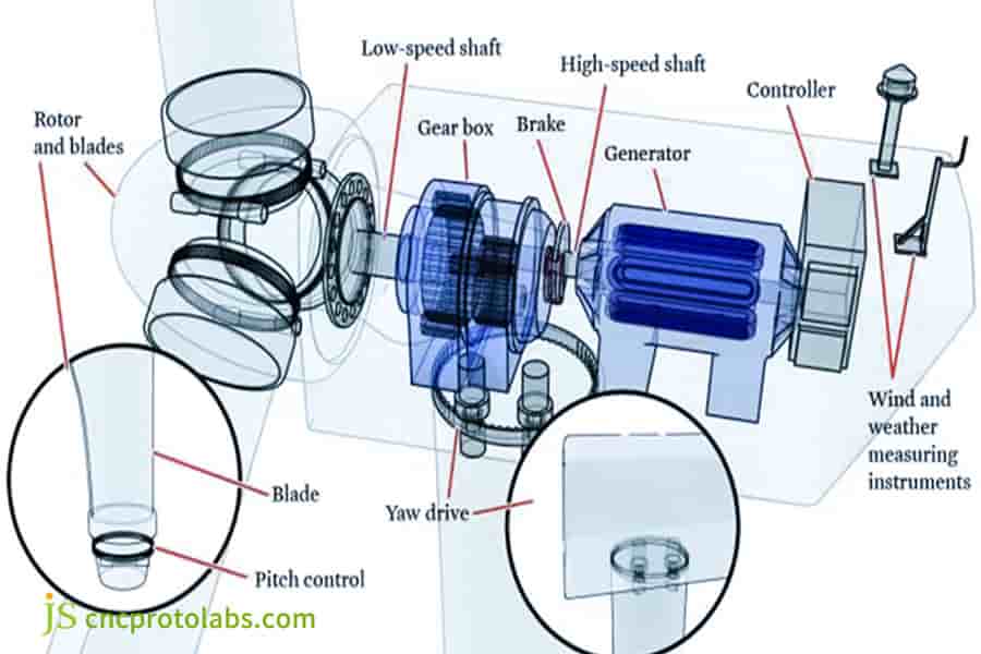
Figure 1: A detailed cut-away diagram showing the internal structure of a wind turbine, highlighting critical components like the gearbox, generator, rotor, and control systems.
How Does Wind Turbine Design Influence The Selection Of Steel Gear Vs. Other Materials?
Wind turbine design is moving towards large-scale development, with requirements for torque density and lightweight materials.
Steel gear functions as the main drive stage material which must fulfill the requirements of IEC 61400-1 for its operating conditions. The main drive stage needs offshore units to use high-strength alloy steel together with carburizing and quenching processes.
The Trade-off Between Torque Density and Lightweighting
The gearbox input torque increases when wind turbine capacity reaches higher values. 10MW wind turbines have input torques exceeding 5000 kN·m.
The design team increased the tooth surface contact stress value for nacelle weight control which resulted in greater requirements for steel gear fatigue performance and gear manufacturing material purity.
Design Prerequisites for Surface Hardening Technology
The design process begins with surface hardening technology which serves as an essential first step. The effective hardened layer depth for wind turbine gears is 0.15-0.25 times the module. The design phase needs grinding allowance to prepare for heat treatment deformation correction which serves as an essential first step in gear machining.
Carburized Layer Depth Requirements for Wind Turbine Steel Gears with Different Modules
| Gear Module | 3 | 5 | 8 | 10 | 12 | 15 |
| Effective Hardened Layer Depth (mm) | 0.45-0.75 | 0.75-1.25 | 1.2-2.0 | 1.8-2.5 | 2.4-3.0 | 2.25-3.75 |
| Grinding Allowance (mm) | 0.2 | 0.2 | 0.25 | 0.3 | 0.3 | 0.3 |
| Surface Hardness (HRC) | 58-62 | 58-62 | 58-62 | 58-62 | 58-62 | 58-62 |
Why Are Aluminum Gears Rarely Used In Main Drives But Relevant In Auxiliary Systems?
The aluminum gears lack sufficient strength for main drive applications which allows their lightweight design to be used in secondary operational systems.
The manufacturing process requires special procedures for both materials which enables a weight reduction of 40 to 60 percent and decreases motor power needs in secondary operational systems.
Physical Limits of Material Strength
The yield strength and contact fatigue limit of aluminum alloys are far lower than the requirements of the main drive stage.
The material exhibits high stress failure tendencies together with a thermal expansion coefficient which causes loss of dimensional accuracy when it operates at elevated temperatures. This is the core reason why aluminum gears are abandoned in the main drive stage.
Lightweight Value of Auxiliary Systems
The contact stress of gears in auxiliary systems is lower, which shows that aluminum gears provide weight reduction benefits. JS Precision performs surface hard anodizing treatment to form a ceramic layer which improves wear resistance to meet requirements.
Have clear requirements and want to customize aluminum gears? Contact an engineer immediately, submit your auxiliary system load parameters, and we will discuss the details of the custom gear manufacturing process one-on-one to finalize a customized solution.
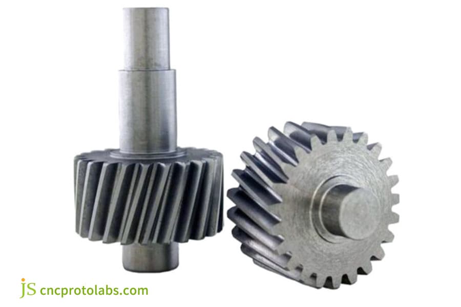
Figure 2: Two high-precision steel helical gears with slanted teeth, manufactured for use in wind turbine auxiliary systems, shown against a plain background.
What Defines a Reliable Steel Gear For Demanding Wind Turbine Applications?
The production of reliable steel gear requires high-quality materials and the implementation of strict manufacturing standards for gear manufacturing. 18CrNiMo7-6 serves as the standard material for wind turbine gearbox production because its quality specifications establish the operational limits which determine gear performance.
Material Grade and Purity Threshold
The 18CrNiMo7-6 carburized steel requires specific chemical composition standards which must be met.
Wind power applications require vacuum degassing treatment which must achieve an oxygen content of 20ppm or lower and sulfur and phosphorus levels below 0.015%. The contact fatigue life of steel gears increases by 15% for every 10ppm decrease in oxygen level.
Grain Size and Toughness
Wind power gear production requires steel gear with grain sizes that exceed grade 6 requirements. Fine-grained structures provide low-temperature impact toughness which enables them to function effectively in severe operating conditions. Coarse grains account for 80% of all brittle fractures which occur in materials.
Which Gear Manufacturing Processes Drive The Final Cost Of Wind Turbine Gears?
The total costs of manufacturing wind turbine gears depend on three factors precision machining activities and heat treatment processes and the characteristics of produced batches which require specialized systems to manage their production requirements.
The process of gear machining establishes the main cost structure because it demands specific precision standards during execution.
1. Precision Machining:
The expenses associated with gear manufacturing reach 30%-40% because gear grinding represents a significant portion of the production process.
ISO Level 4 and Level 6 precision machining require different machining times because the precision requirements between these two levels create a twofold difference in necessary work hours and expenses.
2. Heat Treatment:
The deep carburizing process demands extensive time and energy resources because it needs precise control of furnace temperature distribution. The expenses associated with heat treatment processes break down into two main components which include electricity expenses that account for 40%-50% of total treatment expenses.
3. Batch Effect:
The expenses for small-batch production and debugging processes become expensive but there exists a cost benefit when companies produce 50 units or more because the expenses decrease for each unit.
Limited project budget? Want to control gear manufacturing costs? Provide your gear specifications and purchase quantity for a free calculation of the optimal cost solution to help you reduce costs and increase efficiency.
Can Custom Gear Manufacturing Extend The Lifespan Of a Wind Turbine Gearbox?
Standard gears are unable to function correctly when exposed to operating conditions that exist outside their intended design parameters. Custom gear manufacturing through micro-modification process establishes better load distribution which results in improved surface coverage across the gear.
This system enables wind power facilities to fulfill their specific operational requirements through customized gear manufacturing capabilities.
The Necessity of Customization for Non-Standard Operating Conditions
The selection of parameters for micro-modification needs to be combined with the turbulence level of the wind field and the gear specifications. Modification parameters vary significantly under different operating conditions.
Below is a reference table of standard modification parameters from JS Precision, validated through extensive practical application:
| Turbulence Level | Gear Module | Tooth Profile Modification Amount (μm) | Helical Modification Amount (μm) | Tooth Tip Backflip Amount (μm) | Contact Stress Reduction Rate (%) |
| IIIC Level (Low Turbulence) | 5 | 8-12 | 10-15 | 25-30 | 18-22 |
| IIIB Level (Medium Turbulence) | 8 | 12-18 | 15-20 | 30-35 | 22-26 |
| IIIA Level (High Turbulence) | 10 | 18-25 | 20-28 | 35-40 | 26-30 |
| High Turbulence at Sea | 12 | 22-30 | 25-32 | 40-45 | 28-32 |
| High Turbulence in Complex Terrain | 15 | 25-35 | 28-35 | 45-50 | 30-35 |
The load spectra which IEC 61400-1 defines for various turbulence levels show substantial differences between different turbulence levels. The high-turbulence wind fields require development of custom gears which are specially designed. JS Precision creates a load spectrum reconstruction from SCADA data which helps to decrease design input errors.
The Invisible Value of Micro-shaping
Heavy loads cause the tooth surface to experience elastic deformation. Microscopic modification can compensate for deformation and achieve uniform contact stress. The contact imprint area together with pitting resistance of a 3MW wind turbine steel gear improved through micro-shaping.
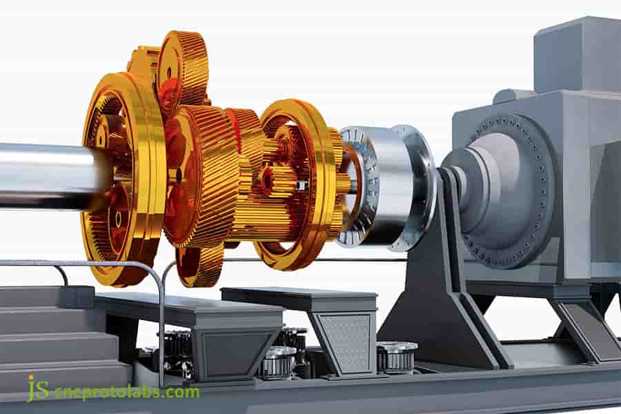
Figure 3: An assembly of intricately designed, golden-colored steel gears connected to a larger component, illustrating the precision of custom-made gears for wind turbine applications.
What Durability Tests Validate The Quality Of Custom Gears Before Installation?
Custom gears require rigorous durability testing before installation. The final quality control procedure in gear production needs to follow ISO 6336-5 and AGMA 6006 standards for proper gear functioning over two decades.
- Back-to-back testing: The FZG test bench requires tests which apply increasing loads until it reaches 1×10⁷ cycles while maintaining both rated torque and overload test conditions defined by IEC 61400-4.
- Non-destructive testing: The testing process uses ultrasonic and magnetic particle methods to find both internal and surface defects while ensuring that critical areas contain no defects that exceed established standards.
- Standard compliance: The strength calculations which follow ISO 6336-5 must be completed to verify that all performance results meet AGMA 6006 standards.
How To Source High Quality Custom Gear Manufacturing Services For Wind Projects?
The selection process for high-quality custom gear manufacturing services requires evaluation of three specific supplier factors which include their equipment, their industry experience, and their complete manufacturing process expertise.
This method provides the necessary testing methodology which ensures reliable performance results for wind turbine gear systems.
Hardware Requirements
Wind turbine gear manufacturing requires large-scale processing and heat treatment equipment. The German NILES forming gear grinding machines at we operate with stable processing accuracy which reaches ISO 3 level and meets their requirements for wind turbine gear processing.
Experience Threshold
The wind turbine gear failure analysis process requires suppliers to demonstrate their work experience in this area. JS Precision operates a failure graph database which contains more than 300 analyzed failure cases for their technicians to use in identifying failure causes and developing optimization solutions.
Full Lifecycle Service
The long development process of wind power projects requires supplier partners to deliver complete life cycle support for their services. The production process which we uses to solidify our manufacturing methods results in consistent product quality with extremely low defect rates during mass delivery while providing stable product availability.
Want to select a high-quality custom gear manufacturing partner? Download our supplier evaluation checklist and quickly filter suppliers. You can also schedule a one-on-one consultation with a technical consultant.
Case Study: JS Precision Overcomes The Problem Of Gear Micro Pitting Corrosion In Offshore Wind Farms Through Micro Modification
Challenge
A 3MW European offshore wind farm uses a high-speed helical gear which developed large-area micropitting after three years of operation because its vibration values exceeded the standard limit by 4.2mm/s.
The original supplier could not solve the problem. The on-site tests revealed that the steel gear tooth surface roughness reached Ra 0.8μm while contact imprints showed only 40% and local contact stress exceeded the maximum allowable limit.
Solution
1.Load spectrum collection:
After JS Precision took over, they first installed torque sensors at the input end of the gearbox and collected operational data for 30 consecutive days. It was found that the actual peak torque was 22% higher than the design value.
2.Shape optimization:
The measured load spectrum served as the foundation for conducting finite element analysis. The tooth profile modification amount was optimized from 12μm to 22μm, the helix modification amount from 8μm to 25μm, and the tooth tip beveling was set to 40μm.
3.Process upgrade:
The gear machining process used CBN grinding wheel worm gear roughing, which progressed to finishing through ceramic bond honing wheel high-power honing to achieve tooth surface roughness of Ra 0.25μm.
4.Verification testing:
The back-to-back test bench testing process successfully completed the verification testing through 2×10⁷ cycles. The 5×10⁵ cycle shutdown checks showed no signs of micropitting.
Results
The optimized gear contact fatigue limit reached 1350 MPa, which resulted in a lifespan extension beyond 100 percent while the vibration level decreased to 2.7 mm/s.
The wind farm turbines operated without any failures for a period of 5 years. Based on an annual equivalent operating hours of 3000 hours, this resulted in a cumulative increase in power generation of 3 million kWh and a direct reduction in downtime losses exceeding $500,000.
Wind farm experiencing gear failures and urgently need a solution? Call our technical hotline immediately, submit your fault detection data, and receive a targeted optimization solution within 72 hours to minimize downtime losses.
FAQs
Q1: What are the most commonly used material grades for wind turbine gearboxes?
The most commonly used materials for wind turbine gearboxes are 18CrNiMo7-6 and 17CrNiMo6 carburized alloy steel. These steel gears maintain their strength above 1200 MPa while they operate between -40℃ and higher temperatures.
Q2: How does the depth of the carburized layer affect gear lifespan?
The main drive steel gear in wind turbines needs a hardened area which extends between 1.5 to 3.0 mm because this depth represents 0.15 to 0.25 of the gear module. Gears will experience early fatigue spalling when the layer depth remains insufficient, leading to a reduction in their operational lifespan.
Q3: What are the differences between ISO 6336 and AGMA standards?
Hertzian stress serves as the basis for contact strength calculations in ISO 6336, while AGMA 6006 establishes a system for power rating classification. The definitions of gear safety factors differ by approximately 15%-20%.
Q4: What problems can gear micro-molding solve?
The process of gear micro-molding enables systems to handle elastic deformation which occurs at tooth surfaces under heavy loads between 10 and 30 micrometers, thus preventing stress concentration while enhancing the gear's ability to resist galling.
Q5: What non-destructive testing is required for wind turbine gears?
All gear components in wind turbine gear manufacturing must undergo ultrasonic testing which achieves a resolution of 0.5 mm and magnetic particle testing which detects both internal and surface defects throughout the manufacturing process.
Q6: What is the working principle of a back-to-back test bench?
The back-to-back test bench employs two gearboxes to create a closed-loop loading system which compensates for 5% to 10% of rated power through frictional losses, thereby replicating the operational testing conditions which require low energy consumption from the gears.
Q7: How to determine whether gear failure is a material issue or a lubrication issue?
Using electron microscopy (SEM) analysis, the fracture caused by internal inclusions is a problem with the gear manufacturing material, while surface scratches or bonding are mostly due to poor lubrication or oil contamination.
Q8: How long does it take from drawings to first piece delivery?
The time required to complete a project starts from the moment of receiving drawings until the delivery of the first piece. JS Precision needs 6-8 weeks to deliver its first piece sample after receiving 3D drawings for conventional wind turbine steel gears which have a diameter range of 8-12 and 2000mm.
Summary
The 20 years of reliability of wind turbine gears stems from meticulous craftsmanship throughout the entire gear manufacturing process, from material purity to machining precision, every step is crucial. The development of wind turbine design has made steel gears a core choice, while custom gear manufacturing is key to adapting to non-standard operating conditions.
For 15 years, JS Precision has dedicated its entire business to the wind power sector, which provides us with complete manufacturing capabilities and considerable expertise in failure investigation.
Our engineering team offers expertise to assist you whether you require standard gear products or custom gear production services. Submit your gear parameters and receive a customized solution and quote within 24 hours.

Disclaimer
The contents of this page are for informational purposes only.JS Precision Services,there are no representations or warranties, express or implied, as to the accuracy, completeness or validity of the information. It should not be inferred that a third-party supplier or manufacturer will provide performance parameters, geometric tolerances, specific design characteristics, material quality and type or workmanship through the JS Precision Network. It's the buyer's responsibility Require parts quotation Identify specific requirements for these sections.Please contact us for more information.
JS Precision Team
JS Precision is an industry-leading company, focus on custom manufacturing solutions. We have over 20 years of experience with over 5,000 customers, and we focus on high precisionCNC machining,Sheet metal manufacturing,3D printing,Injection molding,Metal stamping,and other one-stop manufacturing services.
Our factory is equipped with over 100 state-of-the-art 5-axis machining centers, ISO 9001:2015 certified. We provide fast, efficient and high-quality manufacturing solutions to customers in more than 150 countries around the world. Whether it is small volume production or large-scale customization, we can meet your needs with the fastest delivery within 24 hours. Choose JS Precision this means selection efficiency, quality and professionalism.
To learn more, visit our website:www.cncprotolabs.com
Resource